Heavy Payload Robot
ProductOverview
A heavy payload robot is an industrial arm built to lift loads measured in hundreds of kilograms: engine blocks, car bodies, stacks of bricks, machine castings, full pallets. It does the same job as a smaller robot, moving a tool through a programmed path, but everything about it is scaled up to handle forces that would tear an ordinary arm apart. A 500 kg load held at the end of a three metre arm produces an enormous bending moment, and the whole machine, from the foundation bolts to the wrist bearings, is sized to carry that load while still placing it within a tenth of a millimetre. These robots weigh several tonnes themselves and are the heavy lifters of automotive body shops, foundries, and warehouses.
How it works
The arm is the familiar six-axis layout but in heavy form. The base and arm axes use a Major Joint Module module, the same idea as any robot joint, a Servo Motor driving a reducer, but with an oversized Heavy RV Reducer. The reducer is the part that scales most dramatically: it is a heavy cycloidal unit running in an oil bath with multiple support bearings, because it must transmit thousands of newton-metres without flexing. A Holding Brake on each axis is large enough to hold the loaded arm safely if power is lost, which is a serious concern when half a tonne is hanging in the air.
Everything starts at the Base and Swing, a heavy cast iron foot bolted into a concrete foundation. Its first axis swings the whole machine, and because that axis carries the tilting load of the entire arm, it turns on a large Slewing Ring Bearing slewing ring rather than ordinary bearings. Above it the Shoulder Axis is the single most loaded axis on the robot, lifting the entire arm plus payload against gravity through its full range.
The counterbalance
The shoulder axis would be impractically large if it had to lift the dead weight of the arm as well as the payload, so heavy robots add a Counterbalance. This is usually a Gas Spring Cylinder, a nitrogen-charged cylinder linked to the shoulder so that as the arm folds down the cylinder compresses and pushes back, storing energy, and as the arm rises the cylinder helps lift. The effect is that gravity on the arm itself is largely cancelled out, so the shoulder motor and reducer are sized for the payload rather than for the arm's own mass. This makes the motors smaller, the energy use lower, and the arm safer, since a power loss leaves the counterbalanced arm closer to equilibrium than free-falling.
Structure and wrist
The links between axes, the Arm Link Set, are large castings or fabricated steel weldments, far heavier than the slim links of a small robot because any flex shows up directly as position error at a long reach. The Elbow Axis bends the arm, and at the far end the Heavy Wrist supplies the last three axes. The wrist on a heavy robot is itself a substantial assembly: each Wrist Joint Module is rated for the large moment a heavy tool applies, and the Tool Flange carries a big bolt pattern for spot-weld guns, vacuum frames, or material-handling grippers that themselves weigh tens of kilograms.
Control and power
A robot this size needs more electrical power than a wall outlet provides, so the Controller Cabinet is a floor-standing cabinet rather than a small box. It contains a Power Transformer to match plant supply to the drive bus, and a Servo Drive per axis built around a high-current IGBT Power Module to feed the large servo motors. The Controller Main Board plans the motion, and a redundant Safety Board enforces speed and zone limits, which matters more here because the kinetic energy of a fast-moving half-tonne load makes the safety envelope around the robot large and strictly enforced. An operator works through the Teach Pendant.
Materials and variants
The base and major castings are grey or ductile iron for stiffness and vibration damping, the arm links are often welded steel plate, and the reducer internals are case-hardened alloy steel. The wrist and base are sealed to high IP ratings because these robots work in foundries, weld shops, and outdoors. Payload variants span a wide range, from around 150 kg up to 1300 kg or more for the largest body-handling and press-tending arms, with reach traded against payload: a long-reach version carries less, a short-reach version carries more. Shelf-mounted and inverted variants exist for press lines, and foundry versions add extra sealing and heat shielding.
Use
Heavy payload robots are the backbone of automotive body construction, lifting and positioning entire car bodies between stations, and of press tending, moving large stampings in and out of presses. They handle castings and forgings in foundries, palletise heavy bags and boxes at the end of production lines, and load and unload machine tools that work on big parts. They are chosen wherever the load is simply too heavy for a person or a smaller robot, and where the cost of the large machine is justified by removing a dangerous, physically punishing manual task.
Heavy Payload Robot parts and their functions
7 top-level parts · 1,298 parts in total · full bill of materials below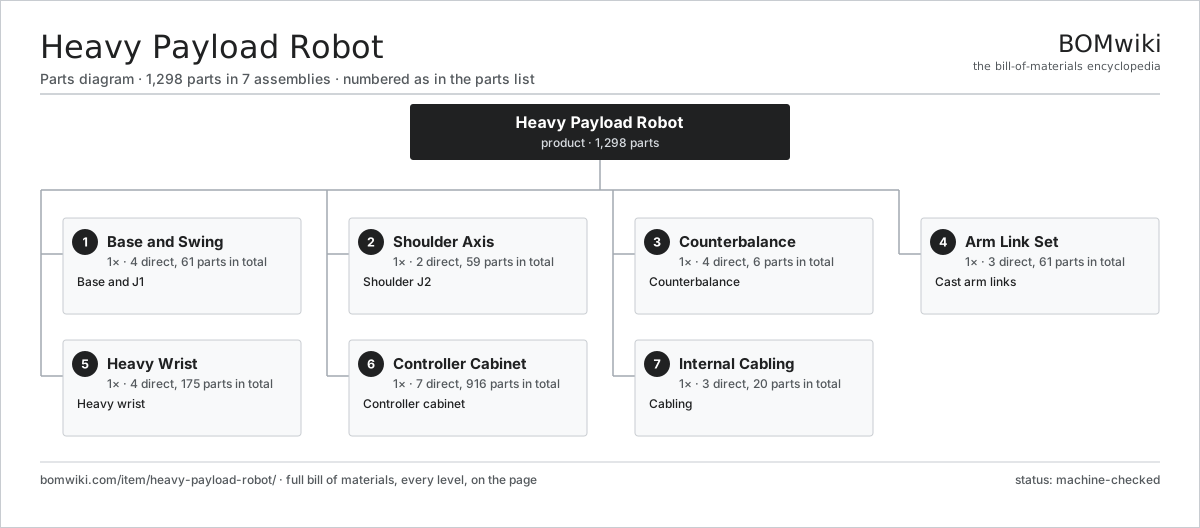
| # | Part | Qty | What it does |
|---|---|---|---|
| 1 | Base and Swing 4 parts | 1× | Base and J1 |
| 2 | Shoulder Axis 2 parts | 1× | Shoulder J2 |
| 3 | Counterbalance 4 parts | 1× | Counterbalance |
| 4 | Arm Link Set 3 parts | 1× | Cast arm links |
| 5 | Heavy Wrist 4 parts | 1× | Heavy wrist |
| 6 | Controller Cabinet 7 parts | 1× | Controller cabinet |
| 7 | Internal Cabling 3 parts | 1× | Cabling |
3D model
No 3D model yet. Have a CAD file of this? Add a 3D model — STL renders right on this page; STEP, FreeCAD, and OpenSCAD sources are welcome too (openly licensed, like all 3D models on BOMwiki).
Build & assembly graph
expand / collapse · shared sub-assemblies converge · links to related products · est. labourTap an assembly to expand/collapse · tap a part to open it · use “Open page” for any node · drag to pan, scroll to zoom.
Bill of materials for Heavy Payload Robot
7 top-level lines · 67 rows shown · 1,298 parts total · indented to 3 levels| # | Item / sub-assembly | Part no. | Qty/assy | Ext. qty | Parts | Type |
|---|---|---|---|---|---|---|
| 1 | Base and Swing 4 parts | heavy-payload-robot-base | 1× | 1 | 61 | assembly |
| 1.1 | Base Casting | heavy-payload-robot-base-casting | 1× | 1 | · | part |
| 1.2 | Major Joint Module 5 parts | heavy-payload-robot-major-joint | 1× | 1 | 58 | assembly |
| 1.2.1 | Servo Motor 4 parts + deeper › | servo-motor | 1× | 1 | 24 | assembly |
| 1.2.2 | Heavy RV Reducer 5 parts + deeper › | heavy-payload-robot-reducer | 1× | 1 | 10 | assembly |
| 1.2.3 | Holding Brake | heavy-payload-robot-brake | 1× | 1 | · | part |
| 1.2.4 | Absolute Encoder 2 parts + deeper › | heavy-payload-robot-encoder | 1× | 1 | 21 | assembly |
| 1.2.5 | Ball Bearing | ball-bearing | 2× | 2 | · | part |
| 1.3 | Slewing Ring Bearing | heavy-payload-robot-slew-bearing | 1× | 1 | · | part |
| 1.4 | Fastener Set | fastener-set | 1× | 1 | · | part |
| 2 | Shoulder Axis 2 parts | heavy-payload-robot-shoulder | 1× | 1 | 59 | assembly |
| 2.1 | Major Joint Module 5 parts | heavy-payload-robot-major-joint | 1× | 1 | 58 | assembly |
| 2.1.1 | Servo Motor 4 parts + deeper › | servo-motor | 1× | 1 | 24 | assembly |
| 2.1.2 | Heavy RV Reducer 5 parts + deeper › | heavy-payload-robot-reducer | 1× | 1 | 10 | assembly |
| 2.1.3 | Holding Brake | heavy-payload-robot-brake | 1× | 1 | · | part |
| 2.1.4 | Absolute Encoder 2 parts + deeper › | heavy-payload-robot-encoder | 1× | 1 | 21 | assembly |
| 2.1.5 | Ball Bearing | ball-bearing | 2× | 2 | · | part |
| 2.2 | Shoulder Casting | heavy-payload-robot-shoulder-casting | 1× | 1 | · | part |
| 3 | Counterbalance 4 parts | heavy-payload-robot-counterbalance | 1× | 1 | 6 | assembly |
| 3.1 | Gas Spring Cylinder | heavy-payload-robot-gas-spring | 1× | 1 | · | part |
| 3.2 | Balance Link | heavy-payload-robot-balance-link | 1× | 1 | · | part |
| 3.3 | Ball Bearing | ball-bearing | 2× | 2 | · | part |
| 3.4 | Pivot Pin | heavy-payload-robot-pivot-pin | 2× | 2 | · | part |
| 4 | Arm Link Set 3 parts | heavy-payload-robot-arm-set | 1× | 1 | 61 | assembly |
| 4.1 | Lower Arm Casting | heavy-payload-robot-lower-arm | 1× | 1 | · | part |
| 4.2 | Upper Arm Casting | heavy-payload-robot-upper-arm | 1× | 1 | · | part |
| 4.3 | Elbow Axis 2 parts | heavy-payload-robot-elbow-joint | 1× | 1 | 59 | assembly |
| 4.3.1 | Major Joint Module 5 parts + deeper › | heavy-payload-robot-major-joint | 1× | 1 | 58 | assembly |
| 4.3.2 | Elbow Casting | heavy-payload-robot-elbow-casting | 1× | 1 | · | part |
| 5 | Heavy Wrist 4 parts | heavy-payload-robot-wrist | 1× | 1 | 175 | assembly |
| 5.1 | Wrist Joint Module 4 parts | heavy-payload-robot-wrist-joint | 3× | 3 | 57 | assembly |
| 5.1.1 | Servo Motor 4 parts + deeper › | servo-motor | 1× | 3 | 24 | assembly |
| 5.1.2 | Heavy RV Reducer 5 parts + deeper › | heavy-payload-robot-reducer | 1× | 3 | 10 | assembly |
| 5.1.3 | Absolute Encoder 2 parts + deeper › | heavy-payload-robot-encoder | 1× | 3 | 21 | assembly |
| 5.1.4 | Ball Bearing | ball-bearing | 2× | 6 | · | part |
| 5.2 | Wrist Housing | heavy-payload-robot-wrist-housing | 1× | 1 | · | part |
| 5.3 | Tool Flange | heavy-payload-robot-tool-flange | 1× | 1 | · | part |
| 5.4 | Helical Gear Pair | gear-pair | 2× | 2 | · | part |
| 6 | Controller Cabinet 7 parts | heavy-payload-robot-controller | 1× | 1 | 916 | assembly |
| 6.1 | Controller Main Board 4 parts | heavy-payload-robot-main-board | 1× | 1 | 235 | assembly |
| 6.1.1 | Bare PCB | pcb-bare | 1× | 1 | · | part |
| 6.1.2 | Microcontroller | mcu | 2× | 2 | · | part |
| 6.1.3 | SMD Passive (R/C/L) | smd-passives | 220× | 220 | · | part |
| 6.1.4 | Connector | connector | 12× | 12 | · | part |
| 6.2 | Servo Drive 5 parts | heavy-payload-robot-servo-drive | 6× | 6 | 98 | assembly |
| 6.2.1 | Bare PCB | pcb-bare | 1× | 6 | · | part |
| 6.2.2 | IGBT Power Module | heavy-payload-robot-igbt-module | 1× | 6 | · | part |
| 6.2.3 | Gate Driver IC | gate-driver-ic | 2× | 12 | · | part |
| 6.2.4 | SMD Passive (R/C/L) | smd-passives | 90× | 540 | · | part |
| 6.2.5 | Connector | connector | 4× | 24 | · | part |
| 6.3 | Power Transformer | heavy-payload-robot-transformer | 1× | 1 | · | part |
| 6.4 | Power Supply | power-supply | 1× | 1 | · | part |
| 6.5 | Safety Board 4 parts | heavy-payload-robot-safety-board | 1× | 1 | 13 | assembly |
| 6.5.1 | Bare PCB | pcb-bare | 1× | 1 | · | part |
| 6.5.2 | Microcontroller | mcu | 2× | 2 | · | part |
| 6.5.3 | Relay | relay | 6× | 6 | · | part |
| 6.5.4 | Connector | connector | 4× | 4 | · | part |
| 6.6 | Cabinet Enclosure | heavy-payload-robot-cabinet | 1× | 1 | · | part |
| 6.7 | Teach Pendant 4 parts | heavy-payload-robot-pendant | 1× | 1 | 77 | assembly |
| 6.7.1 | LCD Panel | lcd-panel | 1× | 1 | · | part |
| 6.7.2 | Pendant Board 4 parts + deeper › | heavy-payload-robot-pendant-board | 1× | 1 | 74 | assembly |
| 6.7.3 | E-Stop Button | heavy-payload-robot-estop | 1× | 1 | · | part |
| 6.7.4 | Pendant Shell | heavy-payload-robot-pendant-shell | 1× | 1 | · | part |
| 7 | Internal Cabling 3 parts | heavy-payload-robot-cabling | 1× | 1 | 20 | assembly |
| 7.1 | Wire Bundle | wire-bundle | 1× | 1 | · | part |
| 7.2 | Connector | connector | 18× | 18 | · | part |
| 7.3 | Cable Carrier | heavy-payload-robot-cable-carrier | 1× | 1 | · | part |
Related products
same domain, ranked by shared parts Seven-Axis Industrial Robot
1,450 parts · shares 5 with this page
Seven-Axis Industrial Robot
1,450 parts · shares 5 with this page
 Welding Robot Cell
999 parts · shares 5 with this page
Welding Robot Cell
999 parts · shares 5 with this page
 Arc Welding Robot
1,532 parts · shares 4 with this page
Arc Welding Robot
1,532 parts · shares 4 with this page
 Robotic Assembly Cell
1,746 parts · shares 5 with this page
Robotic Deburring Cell
1,637 parts · shares 5 with this page
Robotic Depalletizer
1,401 parts · shares 5 with this page
Robotic Assembly Cell
1,746 parts · shares 5 with this page
Robotic Deburring Cell
1,637 parts · shares 5 with this page
Robotic Depalletizer
1,401 parts · shares 5 with this page
Sourcing: possible vendors
Prices, MOQ, and lead times are algorithmic estimates, not quotes, and not claims about these companies. Company mappings are curated by keyword; est. price band $3k–$500k. How estimates work| Vendor | HQ | Specialty | MOQ | Lead time |
|---|---|---|---|---|
|
🇯🇵Fanuc
fanuc.com ↗
|
Oshino, JP | Industrial robots & CNC | 20 units | 10–18 wks |
| abb.com ↗ | Zurich, CH | Industrial robots | 20 units | 10–18 wks |
|
🇯🇵Yaskawa
yaskawa.com ↗
|
Kitakyushu, JP | Robots & motion | 20 units | 10–18 wks |
|
🇩🇪KUKA
kuka.com ↗
|
Augsburg, DE | Industrial robots | 20 units | 10–18 wks |
| universal-robots.com ↗ | Odense, DK | Collaborative robots | 20 units | 10–18 wks |
920-word article