Robot Linear Track
ProductOverview
A robot linear track adds one long straight axis under an industrial robot so the arm can reach work that is spread out further than its own envelope allows. The robot bolts to a moving Robot Carriage that rolls along a fixed Base Beam, turning a single fixed-base manipulator into a machine that can tend several cells, weld a long seam, or load a row of CNC machines from one program. The track is treated as a seventh axis of the robot, so the controller plans motion across the rail and the six arm joints together rather than indexing the rail and then moving the arm separately. This product covers strokes from one to twenty-five metres, built by joining standard beam, rail, and rack modules.
Beam and guideway
The structural spine is the Beam Weldment, a box-section steel weldment that is stress-relieved and then machined so the rail mounting faces lie in one true plane. It transfers the robot weight and the reaction moments from rapid arm swings into the floor through eight Leveling Foot feet and grouted Anchor Plate anchors. Two profiled Linear Guide Rail rails run the full length, each carrying two Runner Block recirculating-ball blocks. The four blocks together form a wide rectangular footprint that resists the tipping moment created when a heavy robot reaches out sideways at the end of the carriage stroke. Lateral Rail Clamp clamps and a Wiper Kit scraper on each block keep the rails located and clean in a chip-laden shop.
Drive line
Travel comes from a Drive Unit that combines an AC Servo Motor with a low-backlash Planetary Gearbox and a hardened Drive Pinion. The pinion meshes with a hardened Gear Rack made from module-4 Rack Segment lengths joined end to end and set to height on ground Rack Shim shims. Rack and pinion is the standard choice for long strokes because, unlike a ball screw, it does not whip or grow heavier as the axis gets longer; the drive cost stays flat per metre. A sprung Preload Bracket holds the pinion in constant mesh to remove backlash, and a Holding Brake spring brake locks the axis whenever drive power is cut so a robot parked mid-rail cannot drift.
Cable management
A robot on a moving base needs every service that a fixed robot needs, delivered while the base travels. The Cable Management system routes these through an articulated Energy Chain running in a guide Chain Trough. Inside it are the robot Wire Bundle power and signal cores and up to three Media Hose lines for compressed air, coolant, or welding shielding gas. The chain ends at a Carriage Junction Box on the carriage, where a sealed Junction Box Enclosure houses a Terminal Set and the breakout Connector interfaces to the robot. Specifying the bend radius and fill of the energy chain correctly is what makes the difference between a track that runs for years and one that suffers cable fatigue failures.
Safety and travel limits
The Limit System guards both ends of travel in layers. A Home Switch sets the absolute reference at power-up, dual Overtravel Switch overtravel switches cut drive power if the soft limits are passed, and a Hard Stop hydraulic absorber at each end physically arrests the carriage if everything upstream fails. A Cam Rail actuates the switches as the carriage approaches. Because a track lets a heavy robot build real momentum over a long run, this three-layer scheme of software limit, electrical switch, and mechanical stop is a hard requirement of the cell safety assessment.
Protection and use
Way Way Covers bellows and a brush Rack Brush Cover over the rack keep grinding dust, weld spatter, and swarf off the precision surfaces, while a central Grease Distribution Block meters lubricant to the blocks and pinion. In service the track is most common in arc-welding lines, large-part machine tending, palletizing across multiple lanes, and press-to-press transfer. Longer beams are shipped in sections and spliced on site, with the rail and rack joints lapped so the carriage crosses them without a position bump. Because the track integrates as a coordinated external axis, the same robot program can weld a five-metre chassis rail in one continuous motion that no fixed-base robot could reach.
Robot Linear Track parts and their functions
10 top-level parts · 147 parts in total · full bill of materials below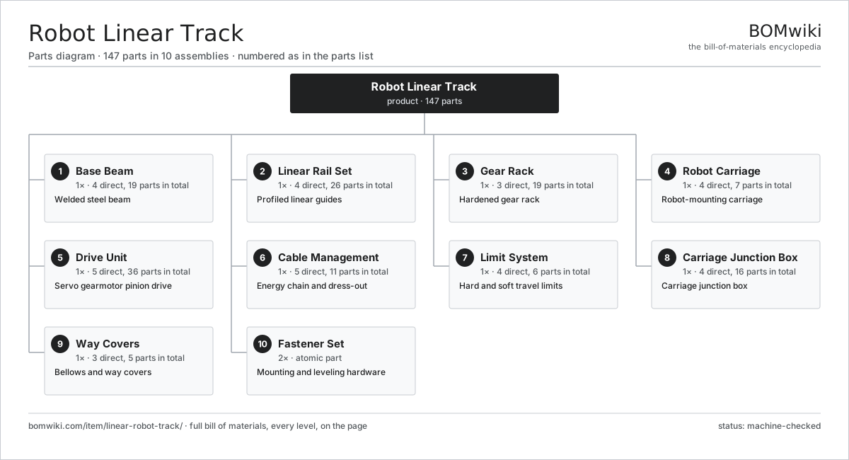
| # | Part | Qty | What it does |
|---|---|---|---|
| 1 | Base Beam 4 parts | 1× | Welded steel beam |
| 2 | Linear Rail Set 4 parts | 1× | Profiled linear guides |
| 3 | Gear Rack 3 parts | 1× | Hardened gear rack |
| 4 | Robot Carriage 4 parts | 1× | Robot-mounting carriage |
| 5 | Drive Unit 5 parts | 1× | Servo gearmotor pinion drive |
| 6 | Cable Management 5 parts | 1× | Energy chain and dress-out |
| 7 | Limit System 4 parts | 1× | Hard and soft travel limits |
| 8 | Carriage Junction Box 4 parts | 1× | Carriage junction box |
| 9 | Way Covers 3 parts | 1× | Bellows and way covers |
| 10 | Fastener Set | 2× | Mounting and leveling hardware |
3D model
No 3D model yet. Have a CAD file of this? Add a 3D model — STL renders right on this page; STEP, FreeCAD, and OpenSCAD sources are welcome too (openly licensed, like all 3D models on BOMwiki).
Build & assembly graph
expand / collapse · shared sub-assemblies converge · links to related products · est. labourTap an assembly to expand/collapse · tap a part to open it · use “Open page” for any node · drag to pan, scroll to zoom.
Bill of materials for Robot Linear Track
10 top-level lines · 54 rows shown · 147 parts total · indented to 3 levels| # | Item / sub-assembly | Part no. | Qty/assy | Ext. qty | Parts | Type |
|---|---|---|---|---|---|---|
| 1 | Base Beam 4 parts | linear-robot-track-base-beam | 1× | 1 | 19 | assembly |
| 1.1 | Beam Weldment | linear-robot-track-beam-weldment | 1× | 1 | · | part |
| 1.2 | Leveling Foot | linear-robot-track-leveling-foot | 8× | 8 | · | part |
| 1.3 | Anchor Plate | linear-robot-track-anchor-plate | 8× | 8 | · | part |
| 1.4 | Machined Datum Pad | linear-robot-track-machined-pad | 2× | 2 | · | part |
| 2 | Linear Rail Set 4 parts | linear-robot-track-rail-set | 1× | 1 | 26 | assembly |
| 2.1 | Linear Guide Rail | linear-guide | 2× | 2 | · | part |
| 2.2 | Runner Block | linear-robot-track-runner-block | 4× | 4 | · | part |
| 2.3 | Rail Clamp | linear-robot-track-rail-clamp | 16× | 16 | · | part |
| 2.4 | Wiper Kit | linear-robot-track-wiper-kit | 4× | 4 | · | part |
| 3 | Gear Rack 3 parts | linear-robot-track-rack | 1× | 1 | 19 | assembly |
| 3.1 | Rack Segment | linear-robot-track-rack-segment | 6× | 6 | · | part |
| 3.2 | Rack Shim | linear-robot-track-rack-shim | 12× | 12 | · | part |
| 3.3 | Fastener Set | fastener-set | 1× | 1 | · | part |
| 4 | Robot Carriage 4 parts | linear-robot-track-carriage | 1× | 1 | 7 | assembly |
| 4.1 | Carriage Plate | linear-robot-track-carriage-plate | 1× | 1 | · | part |
| 4.2 | Robot Adapter Plate | linear-robot-track-robot-adapter | 1× | 1 | · | part |
| 4.3 | Cam Follower | linear-robot-track-cam-follower | 4× | 4 | · | part |
| 4.4 | Grease Distribution Block | linear-robot-track-grease-block | 1× | 1 | · | part |
| 5 | Drive Unit 5 parts | linear-robot-track-drive-unit | 1× | 1 | 36 | assembly |
| 5.1 | Servo Motor 4 parts | servo-motor | 1× | 1 | 24 | assembly |
| 5.1.1 | Stator Assembly 3 parts + deeper › | stator-assembly | 1× | 1 | 3 | assembly |
| 5.1.2 | Rotor Assembly 4 parts + deeper › | rotor-assembly | 1× | 1 | 19 | assembly |
| 5.1.3 | Encoder | encoder | 1× | 1 | · | part |
| 5.1.4 | Motor Housing | motor-housing | 1× | 1 | · | part |
| 5.2 | Planetary Gearbox 4 parts | linear-robot-track-planetary-gearbox | 1× | 1 | 9 | assembly |
| 5.2.1 | Helical Gear Pair | gear-pair | 2× | 2 | · | part |
| 5.2.2 | Gearbox Housing | gearbox-housing | 1× | 1 | · | part |
| 5.2.3 | Ball Bearing | ball-bearing | 4× | 4 | · | part |
| 5.2.4 | Oil Seal | oil-seal | 2× | 2 | · | part |
| 5.3 | Drive Pinion | linear-robot-track-pinion | 1× | 1 | · | part |
| 5.4 | Preload Bracket | linear-robot-track-preload-bracket | 1× | 1 | · | part |
| 5.5 | Holding Brake | linear-robot-track-brake | 1× | 1 | · | part |
| 6 | Cable Management 5 parts | linear-robot-track-cable-management | 1× | 1 | 11 | assembly |
| 6.1 | Energy Chain | linear-robot-track-energy-chain | 1× | 1 | · | part |
| 6.2 | Wire Bundle | wire-bundle | 2× | 2 | · | part |
| 6.3 | Media Hose | linear-robot-track-media-hose | 3× | 3 | · | part |
| 6.4 | Chain Trough | linear-robot-track-chain-trough | 1× | 1 | · | part |
| 6.5 | Connector | connector | 4× | 4 | · | part |
| 7 | Limit System 4 parts | linear-robot-track-limit-system | 1× | 1 | 6 | assembly |
| 7.1 | Hard Stop | linear-robot-track-hard-stop | 2× | 2 | · | part |
| 7.2 | Overtravel Switch | linear-robot-track-limit-switch | 2× | 2 | · | part |
| 7.3 | Home Switch | linear-robot-track-home-switch | 1× | 1 | · | part |
| 7.4 | Cam Rail | linear-robot-track-cam-rail | 1× | 1 | · | part |
| 8 | Carriage Junction Box 4 parts | linear-robot-track-junction-box | 1× | 1 | 16 | assembly |
| 8.1 | Junction Box Enclosure | linear-robot-track-jb-enclosure | 1× | 1 | · | part |
| 8.2 | Terminal Set | linear-robot-track-terminal-set | 1× | 1 | · | part |
| 8.3 | Connector | connector | 6× | 6 | · | part |
| 8.4 | Cable Gland | linear-robot-track-cable-gland | 8× | 8 | · | part |
| 9 | Way Covers 3 parts | linear-robot-track-cover | 1× | 1 | 5 | assembly |
| 9.1 | Protective Bellows | linear-robot-track-bellows | 2× | 2 | · | part |
| 9.2 | Rack Brush Cover | linear-robot-track-rack-cover | 1× | 1 | · | part |
| 9.3 | Sheet Metal Panel | sheet-panel | 2× | 2 | · | part |
| 10 | Fastener Set | fastener-set | 2× | 2 | · | part |
Related products
same domain, ranked by shared parts Robotic Assembly Cell
1,746 parts · shares 4 with this page
Robotic Grinding Cell
1,419 parts · shares 4 with this page
Robotic Screwdriving Cell
2,109 parts · shares 4 with this page
Robotic Palletizing Cell
986 parts · shares 3 with this page
Gantry Loading Robot
800 parts · shares 3 with this page
Robotic Assembly Cell
1,746 parts · shares 4 with this page
Robotic Grinding Cell
1,419 parts · shares 4 with this page
Robotic Screwdriving Cell
2,109 parts · shares 4 with this page
Robotic Palletizing Cell
986 parts · shares 3 with this page
Gantry Loading Robot
800 parts · shares 3 with this page
 Vision-Guided Robot
1,735 parts · shares 2 with this page
Vision-Guided Robot
1,735 parts · shares 2 with this page
Sourcing: possible vendors
Prices, MOQ, and lead times are algorithmic estimates, not quotes, and not claims about these companies. Company mappings are curated by keyword; est. price band $3k–$500k. How estimates work| Vendor | HQ | Specialty | MOQ | Lead time |
|---|---|---|---|---|
|
🇯🇵Fanuc
fanuc.com ↗
|
Oshino, JP | Industrial robots & CNC | 20 units | 10–18 wks |
| abb.com ↗ | Zurich, CH | Industrial robots | 20 units | 10–18 wks |
|
🇯🇵Yaskawa
yaskawa.com ↗
|
Kitakyushu, JP | Robots & motion | 20 units | 10–18 wks |
|
🇩🇪KUKA
kuka.com ↗
|
Augsburg, DE | Industrial robots | 20 units | 10–18 wks |
| universal-robots.com ↗ | Odense, DK | Collaborative robots | 20 units | 10–18 wks |
805-word article