Gantry Loading Robot
ProductOverview
A gantry loading robot is an overhead manipulator that tends one or several machine tools from above rather than from the floor beside them. The bridge structure spans the machine row on floor-anchored columns, and a carriage runs along it carrying a vertical lift column. At the bottom of that column the gripper head reaches down through the open machine door, removes the finished part, drops in a fresh blank, and clears out so the door can close and the cut can start.
The gantry layout has two practical advantages over a floor-standing articulated arm. The first is footprint: the working volume sits above the machine, so floor space stays open for chip carts, the operator and pallet trucks. The second is reach across a line: a single long traverse axis can serve three or four machines in a row, where an articulated arm reaches one machine at a time. The trade is rigidity at long span, which is why the bridge is heavily built and the X axis uses rack and pinion rather than a ball screw.
Structure and axes
The bridge is a welded steel frame: four support columns grouted to the floor carry two box-section bridge beams tied by a cross rail. The top faces are machined and fitted with ground rail mount pads so the linear rails run straight to within a fraction of a millimetre over the full span.
The X axis is the long traverse. Because a ball screw becomes whippy and slow past about two metres, the X axis drives through a hardened rack and pinion turned by a geared servo motor. This gives constant stiffness regardless of length and lets the carriage reach 120 m/min. Riding on the profiled rails is the X carriage, which carries everything below it.
The Y axis is a shorter cross slide driven by a ball screw on its own rails, moving the column across the machine width to reach the chuck centreline. The Z axis is the vertical lift: a welded column tube on vertical guides, lifted by a ball screw with a brake servo motor that holds position if power is lost. A pneumatic counterbalance cylinder carries the dead weight of the column and gripper so the servo only has to accelerate the load, not hold it.
Gripper head and part handling
The gripper head is built for a one-visit exchange. A rotator carries two jaw stations on opposite faces. When the gantry arrives at a machine that has just finished a part, the empty station grips the finished part, the rotator flips 180 degrees, and the loaded station presents a fresh blank to the chuck. This halves the time the machine spends with its door open compared to a single-station gripper that must travel back to the buffer between unload and load.
Each jaw pair uses a pneumatic cylinder driving hardened fingers profiled to the workpiece diameter. A presence sensor confirms the part is seated and a grip pressure sensor confirms clamp force before the gantry moves, so a dropped part is caught immediately. Fingers and the whole jaw set mount through a quick-change coupler so the cell can be set up for a new part family in minutes.
Part buffer and staging
The gantry never picks straight from a tote. It picks from a part buffer where blanks are presented to a known datum. The infeed conveyor indexes raw blanks into pickup nests that locate each part to a fixed position, so the gripper grasps blind with no vision needed. Finished parts go onto the outfeed conveyor or back into locating trays. Both conveyors run on extrusion frames with indexing servo drives and crowned rollers that keep the belts tracking.
Control and machine handshake
The motion controller coordinates the gantry axes with the machine tool, and that handshake is the heart of an unattended cell. The motion card runs the coordinated kinematics and commands one servo drive per axis. The machine interface I/O exchanges the critical signals: the machine reports cycle-complete and door-open, the gantry reports part-clamped and clear. Neither moves into the other's space until the handshake confirms it is safe. An operator HMI handles jogging, recipe selection and fault recovery, and a 24 VDC supply feeds the logic and the motor brakes.
Safety
Because the gantry sweeps overhead at high speed, the safety system guards both the floor and the perimeter. Floor area scanners watch the travel envelope and stop the gantry if a person walks underneath. A welded mesh fence encloses the cell with a coded gate switch that inhibits motion when the access gate is open. Emergency stop buttons feed a pair of safety relays that drop drive power on a Category 0 stop, and a status beacon shows the cell state from across the shop floor.
Cabling and maintenance
Every moving axis drags its services in an energy chain. The cable carrier holds the flex-rated power and signal cable and the gripper air hose so they flex through millions of cycles without fatigue. Routine maintenance is light: the rack and guide rails need periodic lubrication and inspection for chip ingress, the gripper cylinder seals and O-rings are replaced on a wear schedule, and the ball bearings on the conveyor rollers and screw ends are checked for play. Most cells run two shifts unattended once the buffer is loaded, with the operator only refilling blanks and clearing finished trays.
Variants and use
Gantry loaders scale from a single lathe with a short overhead beam to a multi-machine line where one long traverse serves a row of identical machines. Heavier variants handle forged blanks of 60 kg or more with a single deep-throated jaw; lighter variants handle small turned parts with a dual gripper and high-speed traverse. They are common in high-volume turning and grinding shops where the same part runs for thousands of cycles and the value is in keeping spindles cutting around the clock rather than waiting on an operator.
Gantry Loading Robot parts and their functions
9 top-level parts · 800 parts in total · full bill of materials below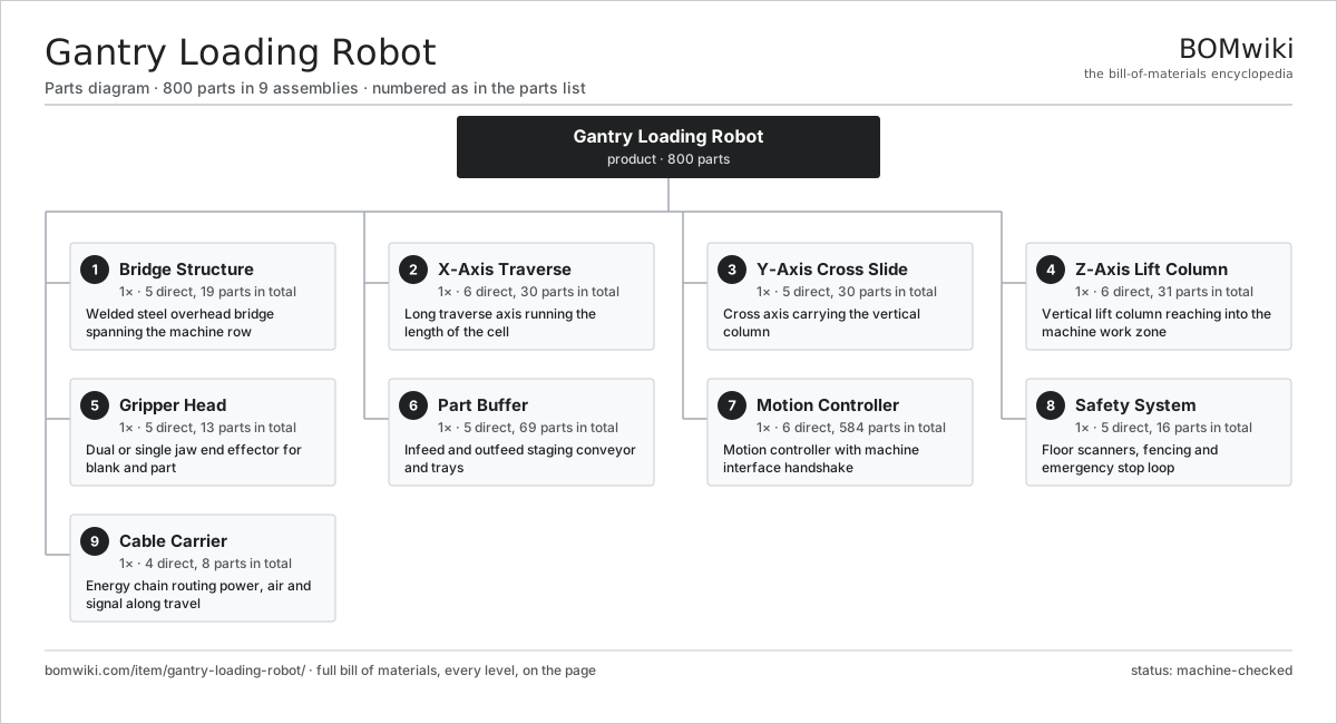
| # | Part | Qty | What it does |
|---|---|---|---|
| 1 | Bridge Structure 5 parts | 1× | Welded steel overhead bridge spanning the machine row |
| 2 | X-Axis Traverse 6 parts | 1× | Long traverse axis running the length of the cell |
| 3 | Y-Axis Cross Slide 5 parts | 1× | Cross axis carrying the vertical column |
| 4 | Z-Axis Lift Column 6 parts | 1× | Vertical lift column reaching into the machine work zone |
| 5 | Gripper Head 5 parts | 1× | Dual or single jaw end effector for blank and part |
| 6 | Part Buffer 5 parts | 1× | Infeed and outfeed staging conveyor and trays |
| 7 | Motion Controller 6 parts | 1× | Motion controller with machine interface handshake |
| 8 | Safety System 5 parts | 1× | Floor scanners, fencing and emergency stop loop |
| 9 | Cable Carrier 4 parts | 1× | Energy chain routing power, air and signal along travel |
3D model
No 3D model yet. Have a CAD file of this? Add a 3D model — STL renders right on this page; STEP, FreeCAD, and OpenSCAD sources are welcome too (openly licensed, like all 3D models on BOMwiki).
Build & assembly graph
expand / collapse · shared sub-assemblies converge · links to related products · est. labourTap an assembly to expand/collapse · tap a part to open it · use “Open page” for any node · drag to pan, scroll to zoom.
Bill of materials for Gantry Loading Robot
9 top-level lines · 91 rows shown · 800 parts total · indented to 3 levels| # | Item / sub-assembly | Part no. | Qty/assy | Ext. qty | Parts | Type |
|---|---|---|---|---|---|---|
| 1 | Bridge Structure 5 parts | gantry-loading-robot-bridge-structure | 1× | 1 | 19 | assembly |
| 1.1 | Support Column | gantry-loading-robot-support-column | 4× | 4 | · | part |
| 1.2 | Bridge Beam | gantry-loading-robot-bridge-beam | 2× | 2 | · | part |
| 1.3 | Cross Rail | gantry-loading-robot-cross-rail | 1× | 1 | · | part |
| 1.4 | Rail Mount Pad | gantry-loading-robot-rail-mount-pad | 8× | 8 | · | part |
| 1.5 | Fastener Set | fastener-set | 4× | 4 | · | part |
| 2 | X-Axis Traverse 6 parts | gantry-loading-robot-x-axis | 1× | 1 | 30 | assembly |
| 2.1 | Linear Guide Rail | linear-guide | 2× | 2 | · | part |
| 2.2 | X-Axis Rack and Pinion | gantry-loading-robot-rack-pinion-x | 1× | 1 | · | part |
| 2.3 | Servo Motor 4 parts | servo-motor | 1× | 1 | 24 | assembly |
| 2.3.1 | Stator Assembly 3 parts + deeper › | stator-assembly | 1× | 1 | 3 | assembly |
| 2.3.2 | Rotor Assembly 4 parts + deeper › | rotor-assembly | 1× | 1 | 19 | assembly |
| 2.3.3 | Encoder | encoder | 1× | 1 | · | part |
| 2.3.4 | Motor Housing | motor-housing | 1× | 1 | · | part |
| 2.4 | Gearbox Housing | gearbox-housing | 1× | 1 | · | part |
| 2.5 | X-Axis Carriage | gantry-loading-robot-x-carriage | 1× | 1 | · | part |
| 2.6 | Cable Trough | gantry-loading-robot-cable-trough | 1× | 1 | · | part |
| 3 | Y-Axis Cross Slide 5 parts | gantry-loading-robot-y-axis | 1× | 1 | 30 | assembly |
| 3.1 | Linear Guide Rail | linear-guide | 2× | 2 | · | part |
| 3.2 | Ball Screw | ball-screw | 1× | 1 | · | part |
| 3.3 | Servo Motor 4 parts | servo-motor | 1× | 1 | 24 | assembly |
| 3.3.1 | Stator Assembly 3 parts + deeper › | stator-assembly | 1× | 1 | 3 | assembly |
| 3.3.2 | Rotor Assembly 4 parts + deeper › | rotor-assembly | 1× | 1 | 19 | assembly |
| 3.3.3 | Encoder | encoder | 1× | 1 | · | part |
| 3.3.4 | Motor Housing | motor-housing | 1× | 1 | · | part |
| 3.4 | Ball Bearing | ball-bearing | 2× | 2 | · | part |
| 3.5 | Y-Axis Saddle | gantry-loading-robot-y-saddle | 1× | 1 | · | part |
| 4 | Z-Axis Lift Column 6 parts | gantry-loading-robot-z-axis | 1× | 1 | 31 | assembly |
| 4.1 | Z Column Tube | gantry-loading-robot-z-column-tube | 1× | 1 | · | part |
| 4.2 | Linear Guide Rail | linear-guide | 2× | 2 | · | part |
| 4.3 | Ball Screw | ball-screw | 1× | 1 | · | part |
| 4.4 | Servo Motor 4 parts | servo-motor | 1× | 1 | 24 | assembly |
| 4.4.1 | Stator Assembly 3 parts + deeper › | stator-assembly | 1× | 1 | 3 | assembly |
| 4.4.2 | Rotor Assembly 4 parts + deeper › | rotor-assembly | 1× | 1 | 19 | assembly |
| 4.4.3 | Encoder | encoder | 1× | 1 | · | part |
| 4.4.4 | Motor Housing | motor-housing | 1× | 1 | · | part |
| 4.5 | Counterbalance Cylinder | gantry-loading-robot-counterbalance | 1× | 1 | · | part |
| 4.6 | Ball Bearing | ball-bearing | 2× | 2 | · | part |
| 5 | Gripper Head 5 parts | gantry-loading-robot-gripper-head | 1× | 1 | 13 | assembly |
| 5.1 | Gripper Rotator | gantry-loading-robot-gripper-rotator | 1× | 1 | · | part |
| 5.2 | Parallel Jaw Pair 3 parts | gantry-loading-robot-jaw-pair | 2× | 2 | 4 | assembly |
| 5.2.1 | Jaw Finger | gantry-loading-robot-jaw-finger | 2× | 4 | · | part |
| 5.2.2 | Gripper Cylinder | gantry-loading-robot-gripper-cylinder | 1× | 2 | · | part |
| 5.2.3 | O-Ring Set | oring-set | 1× | 2 | · | part |
| 5.3 | Part Presence Sensor | gantry-loading-robot-part-sensor | 2× | 2 | · | part |
| 5.4 | Pressure Sensor | pressure-sensor | 1× | 1 | · | part |
| 5.5 | Jaw Quick-Change | gantry-loading-robot-quick-change | 1× | 1 | · | part |
| 6 | Part Buffer 5 parts | gantry-loading-robot-part-buffer | 1× | 1 | 69 | assembly |
| 6.1 | Infeed Conveyor 4 parts | gantry-loading-robot-infeed-conveyor | 1× | 1 | 31 | assembly |
| 6.1.1 | Conveyor Frame | gantry-loading-robot-conveyor-frame | 1× | 1 | · | part |
| 6.1.2 | Servo Motor 4 parts + deeper › | servo-motor | 1× | 1 | 24 | assembly |
| 6.1.3 | Conveyor Roller | gantry-loading-robot-conveyor-roller | 2× | 2 | · | part |
| 6.1.4 | Ball Bearing | ball-bearing | 4× | 4 | · | part |
| 6.2 | Outfeed Conveyor 4 parts | gantry-loading-robot-outfeed-conveyor | 1× | 1 | 31 | assembly |
| 6.2.1 | Conveyor Frame | gantry-loading-robot-conveyor-frame | 1× | 1 | · | part |
| 6.2.2 | Servo Motor 4 parts + deeper › | servo-motor | 1× | 1 | 24 | assembly |
| 6.2.3 | Conveyor Roller | gantry-loading-robot-conveyor-roller | 2× | 2 | · | part |
| 6.2.4 | Ball Bearing | ball-bearing | 4× | 4 | · | part |
| 6.3 | Tray Stack | gantry-loading-robot-tray-stack | 1× | 1 | · | part |
| 6.4 | Drive Belt | drive-belt | 2× | 2 | · | part |
| 6.5 | Pickup Nest | gantry-loading-robot-pickup-nest | 4× | 4 | · | part |
| 7 | Motion Controller 6 parts | gantry-loading-robot-controller | 1× | 1 | 584 | assembly |
| 7.1 | Motion Card 4 parts | gantry-loading-robot-motion-card | 1× | 1 | 130 | assembly |
| 7.1.1 | Bare PCB | pcb-bare | 1× | 1 | · | part |
| 7.1.2 | Microcontroller | mcu | 1× | 1 | · | part |
| 7.1.3 | SMD Passive (R/C/L) | smd-passives | 120× | 120 | · | part |
| 7.1.4 | Connector | connector | 8× | 8 | · | part |
| 7.2 | Servo Drive 5 parts | gantry-loading-robot-servo-drive | 5× | 5 | 90 | assembly |
| 7.2.1 | Bare PCB | pcb-bare | 1× | 5 | · | part |
| 7.2.2 | Power MOSFET | mosfet | 6× | 30 | · | part |
| 7.2.3 | Gate Driver IC | gate-driver-ic | 1× | 5 | · | part |
| 7.2.4 | DC-Link Capacitor | dc-link-cap | 2× | 10 | · | part |
| 7.2.5 | SMD Passive (R/C/L) | smd-passives | 80× | 400 | · | part |
| 7.3 | Machine Interface I/O | gantry-loading-robot-machine-io | 1× | 1 | · | part |
| 7.4 | Power Supply | power-supply | 1× | 1 | · | part |
| 7.5 | Operator HMI | gantry-loading-robot-hmi | 1× | 1 | · | part |
| 7.6 | Microcontroller | mcu | 1× | 1 | · | part |
| 8 | Safety System 5 parts | gantry-loading-robot-safety-system | 1× | 1 | 16 | assembly |
| 8.1 | Floor Area Scanner | gantry-loading-robot-floor-scanner | 2× | 2 | · | part |
| 8.2 | Perimeter Fence 3 parts | gantry-loading-robot-perimeter-fence | 1× | 1 | 8 | assembly |
| 8.2.1 | Sheet Metal Panel | sheet-panel | 6× | 6 | · | part |
| 8.2.2 | Gate Interlock Switch | gantry-loading-robot-gate-switch | 1× | 1 | · | part |
| 8.2.3 | Fastener Set | fastener-set | 1× | 1 | · | part |
| 8.3 | Safety Relay | gantry-loading-robot-safety-relay | 2× | 2 | · | part |
| 8.4 | Emergency Stop Button | gantry-loading-robot-estop | 3× | 3 | · | part |
| 8.5 | Status Beacon | gantry-loading-robot-status-beacon | 1× | 1 | · | part |
| 9 | Cable Carrier 4 parts | gantry-loading-robot-cable-carrier | 1× | 1 | 8 | assembly |
| 9.1 | Energy Chain | gantry-loading-robot-energy-chain | 2× | 2 | · | part |
| 9.2 | Wire Bundle | wire-bundle | 1× | 1 | · | part |
| 9.3 | Air Hose | gantry-loading-robot-air-hose | 1× | 1 | · | part |
| 9.4 | Connector | connector | 4× | 4 | · | part |
Related products
same domain, ranked by shared parts Robotic Assembly Cell
1,746 parts · shares 8 with this page
Robotic Grinding Cell
1,419 parts · shares 8 with this page
Laser Welding Robot
1,294 parts · shares 7 with this page
Machine Tending Robot
1,174 parts · shares 7 with this page
Robotic Assembly Cell
1,746 parts · shares 8 with this page
Robotic Grinding Cell
1,419 parts · shares 8 with this page
Laser Welding Robot
1,294 parts · shares 7 with this page
Machine Tending Robot
1,174 parts · shares 7 with this page
 Vision-Guided Robot
1,735 parts · shares 6 with this page
Vision-Guided Robot
1,735 parts · shares 6 with this page
Sourcing: possible vendors
Prices, MOQ, and lead times are algorithmic estimates, not quotes, and not claims about these companies. Company mappings are curated by keyword; est. price band $3k–$500k. How estimates work| Vendor | HQ | Specialty | MOQ | Lead time |
|---|---|---|---|---|
|
🇯🇵Fanuc
fanuc.com ↗
|
Oshino, JP | Industrial robots & CNC | 20 units | 10–18 wks |
| abb.com ↗ | Zurich, CH | Industrial robots | 20 units | 10–18 wks |
|
🇯🇵Yaskawa
yaskawa.com ↗
|
Kitakyushu, JP | Robots & motion | 20 units | 10–18 wks |
|
🇩🇪KUKA
kuka.com ↗
|
Augsburg, DE | Industrial robots | 20 units | 10–18 wks |
| universal-robots.com ↗ | Odense, DK | Collaborative robots | 20 units | 10–18 wks |
1,275-word article