Wellhead Christmas Tree
ProductOverview
A wellhead christmas tree is the stack of valves, spools and fittings bolted to the top of a producing oil or gas well. It sits on the tubing head and controls every fluid path in and out of the well: production to the flowline, fluid injection for kill or chemical service, and vertical access for wireline and coiled-tubing intervention. The name comes from the branching silhouette of the valve stack. The tree is the surface end of the well's pressure-containment system, so each component is rated and certified to API 6A for the well's maximum shut-in pressure.
A conventional vertical tree routes well flow up a single central bore. Stacked gate valves in that bore form the safety barriers; horizontal wing outlets take production off to the choke and flowline.
How it works
Produced fluid rises through the Tubing Head & Spool, which lands and seals the tubing hanger so the tubing string and the casing annulus stay isolated. Flow then passes the Master Gate Valve gate valves, the lower master is the manual barrier and the upper is a hydraulic fail-safe-close valve that shuts the well automatically if control pressure is lost.
Above the masters, the Flow Cross / Tee splits the vertical bore to the horizontal Wing Valve outlets. The production wing feeds the Adjustable Choke, whose adjustable bean and carbide trim drop pressure and set the flow rate; the kill wing allows fluid to be pumped back in. The Swab Valve caps the top of the bore and opens to give straight vertical access for wireline tools and coiled tubing through a lubricator.
Every actuated valve is driven from the Control Panel, a hydraulic unit whose solenoids and accumulators hold the gates open and bleed down to close them on demand. Operators read tubing and casing pressure from the Pressure Gauge sets, and all spools join through the Flange & Gasket Set of studded API flanges sealed by metal ring-joint gaskets.
Wellhead Christmas Tree parts and their functions
10 top-level parts · 93 parts in total · full bill of materials below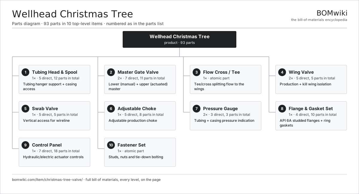
| # | Part | Qty | What it does |
|---|---|---|---|
| 1 | Tubing Head & Spool 5 parts | 1× | Tubing hanger support + casing access |
| 2 | Master Gate Valve 7 parts | 2× | Lower (manual) + upper (actuated) master |
| 3 | Flow Cross / Tee | 1× | Tee/cross splitting flow to the wings |
| 4 | Wing Valve 5 parts | 2× | Production + kill wing isolation |
| 5 | Swab Valve 5 parts | 1× | Vertical access for wireline |
| 6 | Adjustable Choke 5 parts | 1× | Adjustable production choke |
| 7 | Pressure Gauge 3 parts | 2× | Tubing + casing pressure indication |
| 8 | Flange & Gasket Set 4 parts | 1× | API 6A studded flanges + ring gaskets |
| 9 | Control Panel 7 parts | 1× | Hydraulic/electric actuator controls |
| 10 | Fastener Set | 1× | Studs, nuts and tie-down bolting |
3D model
No 3D model yet. Have a CAD file of this? Add a 3D model. STL renders right on this page; STEP, FreeCAD, and OpenSCAD sources are welcome too (openly licensed, like all 3D models on BOMwiki).
Build & assembly graph
expand / collapse · shared sub-assemblies converge · links to related products · est. labourTap an assembly to expand/collapse · tap a part to open it · use “Open page” for any node · drag to pan, scroll to zoom.
Bill of materials for Wellhead Christmas Tree
10 top-level lines · 60 rows shown · 93 parts total · indented to 3 levels| # | Item / sub-assembly | Part no. | Qty/assy | Ext. qty | Parts | Type |
|---|---|---|---|---|---|---|
| 1 | Tubing Head & Spool 5 parts | xt-tubing-head-spool | 1× | 1 | 12 | assembly |
| 1.1 | Spool Body | xt-spool-body | 1× | 1 | · | part |
| 1.2 | Tubing Hanger | xt-tubing-hanger | 1× | 1 | · | part |
| 1.3 | Hanger Seal Stack | xt-hanger-seal | 1× | 1 | · | part |
| 1.4 | Lockdown Screw | xt-lockdown-screw | 8× | 8 | · | part |
| 1.5 | O-Ring Set | oring-set | 1× | 1 | · | part |
| 2 | Master Gate Valve 7 parts | xt-master-valve | 2× | 2 | 11 | assembly |
| 2.1 | Gate Valve Body & Bonnet | xt-gate-valve-body | 1× | 2 | · | part |
| 2.2 | Gate | xt-gate | 1× | 2 | · | part |
| 2.3 | Seat Pair | xt-valve-seat-pair | 1× | 2 | · | part |
| 2.4 | Valve Stem | xt-valve-stem | 1× | 2 | · | part |
| 2.5 | Hydraulic Valve Actuator 5 parts | xt-valve-actuator | 1× | 2 | 5 | assembly |
| 2.5.1 | Actuator Cylinder | xt-actuator-cylinder | 1× | 2 | · | part |
| 2.5.2 | Fail-Safe Spring | xt-actuator-spring | 1× | 2 | · | part |
| 2.5.3 | Position Sensor Stator | xt-position-stator | 1× | 2 | · | part |
| 2.5.4 | Position Sensor Rotor | xt-position-rotor | 1× | 2 | · | part |
| 2.5.5 | O-Ring Set | oring-set | 1× | 2 | · | part |
| 2.6 | O-Ring Set | oring-set | 1× | 2 | · | part |
| 2.7 | Fastener Set | fastener-set | 1× | 2 | · | part |
| 3 | Flow Cross / Tee | xt-flow-cross | 1× | 1 | · | part |
| 4 | Wing Valve 5 parts | xt-wing-valve | 2× | 2 | 5 | assembly |
| 4.1 | Gate Valve Body & Bonnet | xt-gate-valve-body | 1× | 2 | · | part |
| 4.2 | Gate | xt-gate | 1× | 2 | · | part |
| 4.3 | Seat Pair | xt-valve-seat-pair | 1× | 2 | · | part |
| 4.4 | Handwheel | xt-handwheel | 1× | 2 | · | part |
| 4.5 | O-Ring Set | oring-set | 1× | 2 | · | part |
| 5 | Swab Valve 5 parts | xt-swab-valve | 1× | 1 | 5 | assembly |
| 5.1 | Gate Valve Body & Bonnet | xt-gate-valve-body | 1× | 1 | · | part |
| 5.2 | Gate | xt-gate | 1× | 1 | · | part |
| 5.3 | Seat Pair | xt-valve-seat-pair | 1× | 1 | · | part |
| 5.4 | Handwheel | xt-handwheel | 1× | 1 | · | part |
| 5.5 | Tree Cap / Top Connector | xt-top-connector | 1× | 1 | · | part |
| 6 | Adjustable Choke 5 parts | xt-choke-assembly | 1× | 1 | 8 | assembly |
| 6.1 | Choke Body | xt-choke-body | 1× | 1 | · | part |
| 6.2 | Adjustable Bean | xt-choke-bean | 1× | 1 | · | part |
| 6.3 | Carbide Choke Trim | xt-choke-trim | 1× | 1 | · | part |
| 6.4 | Choke Actuator 4 parts | xt-choke-actuator | 1× | 1 | 4 | assembly |
| 6.4.1 | Position Sensor Stator | xt-position-stator | 1× | 1 | · | part |
| 6.4.2 | Position Sensor Rotor | xt-position-rotor | 1× | 1 | · | part |
| 6.4.3 | Helical Gear Pair | gear-pair | 1× | 1 | · | part |
| 6.4.4 | Gearbox Housing | gearbox-housing | 1× | 1 | · | part |
| 6.5 | Choke Position Indicator | xt-choke-indicator | 1× | 1 | · | part |
| 7 | Pressure Gauge 3 parts | xt-pressure-gauge | 2× | 2 | 3 | assembly |
| 7.1 | Pressure Sensor | pressure-sensor | 1× | 2 | · | part |
| 7.2 | Gauge Isolator Valve | xt-gauge-isolator | 1× | 2 | · | part |
| 7.3 | Gauge Dial | xt-gauge-dial | 1× | 2 | · | part |
| 8 | Flange & Gasket Set 4 parts | xt-flange-set | 1× | 1 | 10 | assembly |
| 8.1 | Studded Flange | xt-studded-flange | 4× | 4 | · | part |
| 8.2 | Ring-Joint Gasket | xt-ring-gasket | 4× | 4 | · | part |
| 8.3 | O-Ring Set | oring-set | 1× | 1 | · | part |
| 8.4 | Fastener Set | fastener-set | 1× | 1 | · | part |
| 9 | Control Panel 7 parts | xt-control-panel | 1× | 1 | 18 | assembly |
| 9.1 | Bare PCB | pcb-bare | 1× | 1 | · | part |
| 9.2 | Microcontroller | mcu | 1× | 1 | · | part |
| 9.3 | Hydraulic Charge Pump | xt-hydraulic-pump | 1× | 1 | · | part |
| 9.4 | Pilot Solenoid Valve | xt-solenoid-valve | 4× | 4 | · | part |
| 9.5 | Relay | relay | 4× | 4 | · | part |
| 9.6 | Wire Bundle | wire-bundle | 1× | 1 | · | part |
| 9.7 | Connector | connector | 6× | 6 | · | part |
| 10 | Fastener Set | fastener-set | 1× | 1 | · | part |
Something wrong in this list? Report a problem with this BOM.
Related products
same domain, ranked by shared parts Coiled Tubing Unit
190 parts · shares 2 with this page
 Drilling Top Drive
181 parts · shares 2 with this page
 Hydraulic Fracturing Pump
145 parts · shares 2 with this page
 Oil Pumpjack
141 parts · shares 2 with this page
 Oil-Gas Separator
87 parts · shares 2 with this page
Sourcing: possible vendors
Browse the supplier directory → Prices, MOQ, and lead times are algorithmic estimates, not quotes, and not claims about these companies. Company mappings are curated by keyword; est. price band $10k–$50M. How estimates work| Vendor | HQ | Specialty | MOQ | Lead time |
|---|---|---|---|---|
|
🇺🇸SLB
slb.com ↗
|
Houston, US | Oilfield services & equipment | made to order | 24–48 wks |
| halliburton.com ↗ | Houston, US | Oilfield services | made to order | 24–48 wks |
| bakerhughes.com ↗ | Houston, US | Energy technology | made to order | 24–48 wks |
|
🇺🇸NOV
nov.com ↗
|
Houston, US | Drilling equipment | made to order | 24–48 wks |
| technipfmc.com ↗ | London, GB | Subsea & surface systems | made to order | 24–48 wks |
336-word article