Wellhead Sand Separator
ProductOverview
A wellhead sand separator, often called a desander, removes solid particles from the wellstream before they reach downstream equipment. Many wells, particularly gas wells and any well that has been hydraulically fractured with proppant, produce sand along with hydrocarbons. That sand is abrasive, and at production velocities it erodes chokes, valves, flow lines and separator internals within hours. The sand separator sits at or near the wellhead, immediately downstream of the production choke and upstream of any pressure vessel such as a Three-Phase Production Separator or Well Test Separator Skid, so the sand is caught before it can do damage.
The unit works by centrifugal force rather than gravity, because the high pressure and high velocity at the wellhead leave little room for a settling vessel. Flow enters the Cyclone Insert tangentially and spins rapidly around the inside wall. The denser sand particles are thrown outward and downward along the cone, while the lighter gas and liquid spiral inward and rise out through the vortex finder at the top. The separated sand falls into the Sand Accumulator below, where it is stored and periodically purged.
How the cyclone works
The heart of the unit is the cyclone insert. Fluid enters the Tangential Inlet Nozzle tangentially, which sets the whole stream rotating. Inside the cyclone body the rotation creates a strong centrifugal field, many times the force of gravity, so even fine particles are driven to the wall. The tapering cone increases the rotational speed as the diameter shrinks, concentrating the sand toward the apex. A replaceable apex orifice meters the sand downward into the accumulator while limiting the amount of process fluid that escapes with it.
Clean gas and liquid form an inner spiral that reverses direction and flows up through the vortex finder, a central tube that draws fluid from the low-solids core of the cyclone. The vortex finder geometry sets the cut point, the particle size above which separation is reliable, typically 25 microns and larger at 98 percent efficiency. Because the cyclone is the most heavily eroded component, it is made of tungsten carbide and designed as a quick-change insert so it can be replaced without scrapping the vessel.
Sand handling and purge
Separated sand collects in the accumulator until it is removed. The Flush and Purge System fluidizes the settled bed with water or gas jetting nozzles, turning the packed sand into a pumpable slurry. The accumulator is built as a lock hopper with an upper and a lower isolation valve. To purge, the upper valve closes to isolate the accumulator from process pressure, the lower valve opens to drain the sand to an atmospheric Sand Catch Tank, and the valves then reverse to return the accumulator to service. This lets the unit dump sand continuously without shutting in the well.
The purge is automated by the Sand Level and Dump Control system. An acoustic sand detector clamped to the inlet piping senses the rate of sand impacts, and a level probe in the accumulator reports how full it is. A sequence controller runs the lock-hopper steps in the correct order with interlocks, driving the hydraulic actuators on the isolation valves so that the two valves are never open at the same time.
Erosion protection
Sand at wellhead velocity erodes steel quickly, so the Erosion Protection package hardens every surface the sand touches at speed. The inlet and cyclone are lined with tungsten carbide, replaceable wear sleeves protect the high-velocity passages, and a sacrificial impingement target block takes the direct hit of the inlet jet. An erosion probe on the outlet monitors metal loss so the operator knows when liners need changing. These measures extend service intervals from hours to months in heavy sand service.
Pressure rating and safety
Because the unit sits at the wellhead, it must hold the full shut-in pressure of the well, which can reach 10,000 psi. The High-Pressure Vessel is a thick-wall forging or rolled body built to ASME Section VIII, with API 6A or high-class ANSI flanges. The Relief and Isolation train protects against overpressure with an ASME relief valve and a backup rupture disc, and an inlet emergency shutdown valve isolates the well on a trip. Pressure transmitters feed the facility safety system so that a high or low pressure event closes the inlet automatically.
Variants and use
Single cyclone units serve a single well, while multi-cyclone banks handle the higher flow of a manifold or several wells in parallel. Some designs combine the desander with a filter stage for finer cleanup downstream. Sand separators are most common on fractured gas wells during flowback, where sand production is highest, and on mature wells where formation sand starts to migrate as reservoir pressure declines. By catching sand at the source, the unit protects the choke, the flow line and every vessel downstream, and it keeps abrasive solids out of the produced water that the facility must later treat.
Wellhead Sand Separator parts and their functions
8 top-level parts · 52 parts in total · full bill of materials below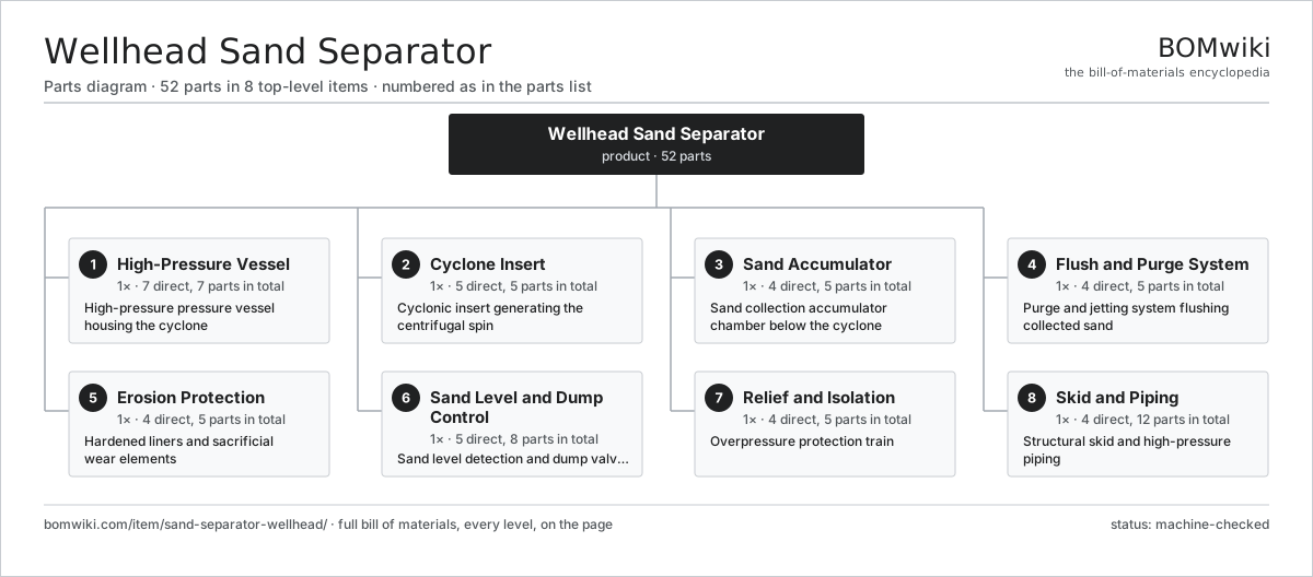
| # | Part | Qty | What it does |
|---|---|---|---|
| 1 | High-Pressure Vessel 7 parts | 1× | High-pressure pressure vessel housing the cyclone |
| 2 | Cyclone Insert 5 parts | 1× | Cyclonic insert generating the centrifugal spin |
| 3 | Sand Accumulator 4 parts | 1× | Sand collection accumulator chamber below the cyclone |
| 4 | Flush and Purge System 4 parts | 1× | Purge and jetting system flushing collected sand |
| 5 | Erosion Protection 4 parts | 1× | Hardened liners and sacrificial wear elements |
| 6 | Sand Level and Dump Control 5 parts | 1× | Sand level detection and dump valve control |
| 7 | Relief and Isolation 4 parts | 1× | Overpressure protection train |
| 8 | Skid and Piping 4 parts | 1× | Structural skid and high-pressure piping |
3D model
No 3D model yet. Have a CAD file of this? Add a 3D model. STL renders right on this page; STEP, FreeCAD, and OpenSCAD sources are welcome too (openly licensed, like all 3D models on BOMwiki).
Build & assembly graph
expand / collapse · shared sub-assemblies converge · links to related products · est. labourTap an assembly to expand/collapse · tap a part to open it · use “Open page” for any node · drag to pan, scroll to zoom.
Bill of materials for Wellhead Sand Separator
8 top-level lines · 45 rows shown · 52 parts total · indented to 3 levels| # | Item / sub-assembly | Part no. | Qty/assy | Ext. qty | Parts | Type |
|---|---|---|---|---|---|---|
| 1 | High-Pressure Vessel 7 parts | sand-separator-wellhead-vessel | 1× | 1 | 7 | assembly |
| 1.1 | Vessel Body | sand-separator-wellhead-shell | 1× | 1 | · | part |
| 1.2 | Top Head | sand-separator-wellhead-top-head | 1× | 1 | · | part |
| 1.3 | Bottom Head | sand-separator-wellhead-bottom-head | 1× | 1 | · | part |
| 1.4 | Tangential Inlet Nozzle | sand-separator-wellhead-inlet-nozzle | 1× | 1 | · | part |
| 1.5 | Clean Outlet Nozzle | sand-separator-wellhead-outlet-nozzle | 1× | 1 | · | part |
| 1.6 | Manway | sand-separator-wellhead-manway | 1× | 1 | · | part |
| 1.7 | Fastener Set | fastener-set | 1× | 1 | · | part |
| 2 | Cyclone Insert 5 parts | sand-separator-wellhead-cyclone | 1× | 1 | 5 | assembly |
| 2.1 | Cyclone Body | sand-separator-wellhead-cyclone-body | 1× | 1 | · | part |
| 2.2 | Vortex Finder | sand-separator-wellhead-vortex-finder | 1× | 1 | · | part |
| 2.3 | Cyclone Cone | sand-separator-wellhead-cone | 1× | 1 | · | part |
| 2.4 | Apex Orifice | sand-separator-wellhead-apex | 1× | 1 | · | part |
| 2.5 | O-Ring Set | oring-set | 1× | 1 | · | part |
| 3 | Sand Accumulator 4 parts | sand-separator-wellhead-accumulator | 1× | 1 | 5 | assembly |
| 3.1 | Accumulator Body | sand-separator-wellhead-accumulator-body | 1× | 1 | · | part |
| 3.2 | Isolation Valve | sand-separator-wellhead-isolation-valve | 2× | 2 | · | part |
| 3.3 | Sand Drain Port | sand-separator-wellhead-drain-port | 1× | 1 | · | part |
| 3.4 | Accumulator Wear Cone | sand-separator-wellhead-wear-cone | 1× | 1 | · | part |
| 4 | Flush and Purge System 4 parts | sand-separator-wellhead-flush-system | 1× | 1 | 5 | assembly |
| 4.1 | Flush Nozzle | sand-separator-wellhead-flush-nozzle | 2× | 2 | · | part |
| 4.2 | Flush Valve | sand-separator-wellhead-flush-valve | 1× | 1 | · | part |
| 4.3 | Purge Line | sand-separator-wellhead-purge-line | 1× | 1 | · | part |
| 4.4 | Flush Strainer | sand-separator-wellhead-strainer | 1× | 1 | · | part |
| 5 | Erosion Protection 4 parts | sand-separator-wellhead-erosion-protection | 1× | 1 | 5 | assembly |
| 5.1 | Carbide Liner | sand-separator-wellhead-carbide-liner | 1× | 1 | · | part |
| 5.2 | Wear Sleeve | sand-separator-wellhead-wear-sleeve | 2× | 2 | · | part |
| 5.3 | Impingement Target Block | sand-separator-wellhead-target-block | 1× | 1 | · | part |
| 5.4 | Erosion Probe | sand-separator-wellhead-erosion-probe | 1× | 1 | · | part |
| 6 | Sand Level and Dump Control 5 parts | sand-separator-wellhead-control | 1× | 1 | 8 | assembly |
| 6.1 | Acoustic Sand Detector | sand-separator-wellhead-acoustic-detector | 1× | 1 | · | part |
| 6.2 | Sand Level Probe | sand-separator-wellhead-level-probe | 1× | 1 | · | part |
| 6.3 | Purge Sequence Controller | sand-separator-wellhead-sequence-controller | 1× | 1 | · | part |
| 6.4 | Valve Actuator | sand-separator-wellhead-actuator | 2× | 2 | · | part |
| 6.5 | Relay | relay | 3× | 3 | · | part |
| 7 | Relief and Isolation 4 parts | sand-separator-wellhead-relief | 1× | 1 | 5 | assembly |
| 7.1 | Relief Valve | sand-separator-wellhead-relief-valve | 1× | 1 | · | part |
| 7.2 | Rupture Disc | sand-separator-wellhead-rupture-disc | 1× | 1 | · | part |
| 7.3 | Inlet Shutdown Valve | sand-separator-wellhead-inlet-sdv | 1× | 1 | · | part |
| 7.4 | Pressure Sensor | pressure-sensor | 2× | 2 | · | part |
| 8 | Skid and Piping 4 parts | sand-separator-wellhead-skid | 1× | 1 | 12 | assembly |
| 8.1 | Skid Frame | sand-separator-wellhead-skid-frame | 1× | 1 | · | part |
| 8.2 | Pipe Spool | sand-separator-wellhead-pipe-spool | 4× | 4 | · | part |
| 8.3 | Sand Catch Tank | sand-separator-wellhead-catch-tank | 1× | 1 | · | part |
| 8.4 | Pipe Support | sand-separator-wellhead-pipe-support | 6× | 6 | · | part |
Sourcing: possible vendors
Browse the supplier directory → Prices, MOQ, and lead times are algorithmic estimates, not quotes, and not claims about these companies. Company mappings are curated by keyword; est. price band $10k–$50M. How estimates work| Vendor | HQ | Specialty | MOQ | Lead time |
|---|---|---|---|---|
|
🇺🇸SLB
slb.com ↗
|
Houston, US | Oilfield services & equipment | made to order | 24–48 wks |
| halliburton.com ↗ | Houston, US | Oilfield services | made to order | 24–48 wks |
| bakerhughes.com ↗ | Houston, US | Energy technology | made to order | 24–48 wks |
|
🇺🇸NOV
nov.com ↗
|
Houston, US | Drilling equipment | made to order | 24–48 wks |
| technipfmc.com ↗ | London, GB | Subsea & surface systems | made to order | 24–48 wks |
841-word article