Drilling Mud Degasser
ProductOverview
A drilling mud degasser removes entrained and dissolved gas from the drilling fluid that returns from the wellbore. When a well takes a gas influx, or kick, formation gas mixes into the mud and lowers its density. Gas-cut mud reduces the hydrostatic head in the annulus, which can let still more gas in, so the gas has to be stripped out before the mud is pumped back down the hole. The vacuum-type degasser is the standard tool for this duty. It sits in the active mud system after the shale shakers and ahead of the mud pumps, and it handles the smaller, finely dispersed gas that a poor-boy or atmospheric separator cannot pull out.
The unit is built around a Vacuum Vessel held under partial vacuum by a Liquid-Ring Vacuum Pump. A Rotor Spreader Drive throws the incoming mud into a thin film, and the lower pressure inside the vessel lets gas break out of that film. Degassed mud is returned to the pit by a Mud Discharge Pump, and the liberated gas is sent to a flare through the Gas Vent Line.
How It Works
Gas-cut mud is drawn into the vessel through the Mud Feed Line. The vacuum inside the vessel helps lift the mud, and a Feed Regulating Valve sets the feed rate while a Feed Basket Strainer catches cuttings that would jam the spreader. Inside the vessel the Spreader Impeller throws the mud outward onto the top Cascade Spreading Tray. The mud then sheets down a stack of inclined trays, breaking into a thin film at each step.
Spreading the mud thin is the key to the process. Gas escapes a thin film far faster than it escapes a thick stream, and the lower the pressure above the film, the more dissolved gas comes out of solution. The Liquid-Ring Vacuum Pump holds the vessel at roughly 0.3-0.5 bar absolute. As mud cascades down the trays, free and dissolved gas is released and rises to the top of the vessel, where a Mist Eliminator Pad knocks out carried mud droplets so the gas leaves reasonably clean.
The released gas is pulled out by the liquid-ring vacuum pump. A Ring Pump Impeller spins service water into a ring against the offset Liquid-Ring Casing, forming the moving compression cells that draw gas from the vessel and push it to the vent. The seal water is cooled and recirculated from a Service-Liquid Tank. From the pump the gas passes through a Liquid Knock-Out Pot and a Deflagration Flame Arrestor before reaching the flare. The flame arrestor stops a flare flame front from running back into the vessel.
Degassed mud collects in the sump at the bottom of the vessel. The Mud Discharge Pump returns it to the active pit. Because the sump is under vacuum, the discharge pump and the Hydraulic Seal Leg have to be arranged so the pump never breaks the vacuum by sucking air through an empty sump. A Level Float Switch and a level transmitter hold the sump level within a band, and the Level Control Valve trims the discharge rate to match the feed.
Materials
The vessel shell and heads are carbon steel built to a pressure-vessel code, since the tank has to resist collapse under full vacuum. Parts that see flowing mud are abrasion-resistant: the Spreader Impeller is hard-faced, the Discharge Impeller is cast in Ni-hard iron, and the cascade trays are stainless sheet. Seals on the rotating shafts, including the Vacuum Shaft Seal, use carbon and silicon-carbide faces to survive the abrasive fluid. The O-Ring Set elastomers are chosen for compatibility with oil-based and water-based muds.
Variants
The most common form is the vacuum-spreader unit described here. A horizontal vessel is normal on a skid-mounted package, but vertical vessels are used where deck space is tight, such as on offshore rigs. Some designs replace the motor-driven spreader with a passive cascade that relies on feed pressure alone, which is simpler but less effective on light, heavily gas-cut mud. The vacuum source is usually a liquid-ring pump, though small units sometimes use an air-driven jet eductor instead. Motor and instrument ratings follow the area classification of the rig, normally ATEX or IECEx Zone 1 with Ex d enclosures.
Use
In service the degasser runs continuously whenever the mud is gas-cut. The crew watches the Compound Vacuum Gauge and the sump level through the Sight Glass Window, and the Control Panel trips the unit on high level or loss of vacuum. The strainer basket is cleaned at intervals, the seal water is topped up, and the vent line is checked so the flame arrestor stays clear. Removing entrained gas restores mud density and protects the mud pumps, which lose efficiency and cavitate when fed aerated fluid.
Drilling Mud Degasser parts and their functions
9 top-level parts · 154 parts in total · full bill of materials below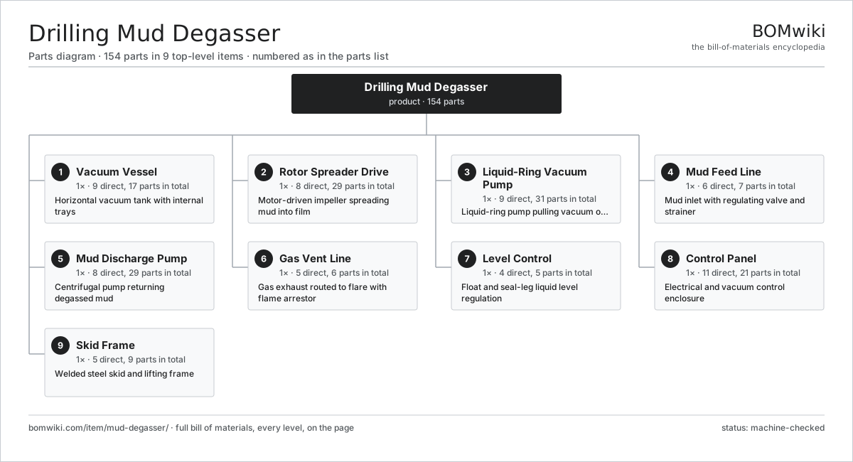
| # | Part | Qty | What it does |
|---|---|---|---|
| 1 | Vacuum Vessel 9 parts | 1× | Horizontal vacuum tank with internal trays |
| 2 | Rotor Spreader Drive 8 parts | 1× | Motor-driven impeller spreading mud into film |
| 3 | Liquid-Ring Vacuum Pump 9 parts | 1× | Liquid-ring pump pulling vacuum on the vessel |
| 4 | Mud Feed Line 6 parts | 1× | Mud inlet with regulating valve and strainer |
| 5 | Mud Discharge Pump 8 parts | 1× | Centrifugal pump returning degassed mud |
| 6 | Gas Vent Line 5 parts | 1× | Gas exhaust routed to flare with flame arrestor |
| 7 | Level Control 4 parts | 1× | Float and seal-leg liquid level regulation |
| 8 | Control Panel 11 parts | 1× | Electrical and vacuum control enclosure |
| 9 | Skid Frame 5 parts | 1× | Welded steel skid and lifting frame |
3D model
No 3D model yet. Have a CAD file of this? Add a 3D model. STL renders right on this page; STEP, FreeCAD, and OpenSCAD sources are welcome too (openly licensed, like all 3D models on BOMwiki).
Build & assembly graph
expand / collapse · shared sub-assemblies converge · links to related products · est. labourTap an assembly to expand/collapse · tap a part to open it · use “Open page” for any node · drag to pan, scroll to zoom.
Bill of materials for Drilling Mud Degasser
9 top-level lines · 95 rows shown · 154 parts total · indented to 3 levels| # | Item / sub-assembly | Part no. | Qty/assy | Ext. qty | Parts | Type |
|---|---|---|---|---|---|---|
| 1 | Vacuum Vessel 9 parts | mud-degasser-vacuum-vessel | 1× | 1 | 17 | assembly |
| 1.1 | Vessel Shell | mud-degasser-vessel-shell | 1× | 1 | · | part |
| 1.2 | Dished End Head | mud-degasser-vessel-head | 2× | 2 | · | part |
| 1.3 | Cascade Spreading Tray | mud-degasser-cascade-tray | 6× | 6 | · | part |
| 1.4 | Mist Eliminator Pad | mud-degasser-mist-eliminator | 1× | 1 | · | part |
| 1.5 | Sight Glass Window | mud-degasser-sight-glass | 2× | 2 | · | part |
| 1.6 | Compound Vacuum Gauge | mud-degasser-vacuum-gauge | 2× | 2 | · | part |
| 1.7 | Pressure Sensor | pressure-sensor | 1× | 1 | · | part |
| 1.8 | Inspection Manway | mud-degasser-vessel-manway | 1× | 1 | · | part |
| 1.9 | O-Ring Set | oring-set | 1× | 1 | · | part |
| 2 | Rotor Spreader Drive 8 parts | mud-degasser-rotor-spreader | 1× | 1 | 29 | assembly |
| 2.1 | Spreader Impeller | mud-degasser-spreader-impeller | 1× | 1 | · | part |
| 2.2 | Rotor Shaft | mud-degasser-rotor-shaft | 1× | 1 | · | part |
| 2.3 | Vacuum Shaft Seal | mud-degasser-mechanical-seal | 1× | 1 | · | part |
| 2.4 | Stator Assembly 3 parts | stator-assembly | 1× | 1 | 3 | assembly |
| 2.4.1 | Stator Core (laminations) | stator-core | 1× | 1 | · | part |
| 2.4.2 | Copper Winding | copper-winding | 1× | 1 | · | part |
| 2.4.3 | Slot Insulation | stator-insulation | 1× | 1 | · | part |
| 2.5 | Rotor Assembly 4 parts | rotor-assembly | 1× | 1 | 19 | assembly |
| 2.5.1 | Rotor Shaft | rotor-shaft | 1× | 1 | · | part |
| 2.5.2 | Rotor Core | rotor-core | 1× | 1 | · | part |
| 2.5.3 | Neodymium Magnet | neodymium-magnet | 16× | 16 | · | part |
| 2.5.4 | Ball Bearing | ball-bearing | 1× | 1 | · | part |
| 2.6 | Ball Bearing | ball-bearing | 2× | 2 | · | part |
| 2.7 | Oil Seal | oil-seal | 1× | 1 | · | part |
| 2.8 | Motor and Bearing Housing | mud-degasser-motor-housing | 1× | 1 | · | part |
| 3 | Liquid-Ring Vacuum Pump 9 parts | mud-degasser-vacuum-pump | 1× | 1 | 31 | assembly |
| 3.1 | Liquid-Ring Casing | mud-degasser-pump-casing | 1× | 1 | · | part |
| 3.2 | Ring Pump Impeller | mud-degasser-pump-impeller | 1× | 1 | · | part |
| 3.3 | Service-Liquid Tank | mud-degasser-seal-water-tank | 1× | 1 | · | part |
| 3.4 | Vacuum Relief Valve | mud-degasser-vacuum-relief-valve | 1× | 1 | · | part |
| 3.5 | Stator Assembly 3 parts | stator-assembly | 1× | 1 | 3 | assembly |
| 3.5.1 | Stator Core (laminations) | stator-core | 1× | 1 | · | part |
| 3.5.2 | Copper Winding | copper-winding | 1× | 1 | · | part |
| 3.5.3 | Slot Insulation | stator-insulation | 1× | 1 | · | part |
| 3.6 | Rotor Assembly 4 parts | rotor-assembly | 1× | 1 | 19 | assembly |
| 3.6.1 | Rotor Shaft | rotor-shaft | 1× | 1 | · | part |
| 3.6.2 | Rotor Core | rotor-core | 1× | 1 | · | part |
| 3.6.3 | Neodymium Magnet | neodymium-magnet | 16× | 16 | · | part |
| 3.6.4 | Ball Bearing | ball-bearing | 1× | 1 | · | part |
| 3.7 | Ball Bearing | ball-bearing | 2× | 2 | · | part |
| 3.8 | Oil Seal | oil-seal | 2× | 2 | · | part |
| 3.9 | Drive Belt | drive-belt | 1× | 1 | · | part |
| 4 | Mud Feed Line 6 parts | mud-degasser-feed-line | 1× | 1 | 7 | assembly |
| 4.1 | Feed Regulating Valve | mud-degasser-feed-valve | 1× | 1 | · | part |
| 4.2 | Feed Basket Strainer | mud-degasser-feed-strainer | 1× | 1 | · | part |
| 4.3 | Tangential Feed Nozzle | mud-degasser-feed-nozzle | 1× | 1 | · | part |
| 4.4 | Feed Pipe Flange | mud-degasser-feed-flange | 2× | 2 | · | part |
| 4.5 | Pressure Sensor | pressure-sensor | 1× | 1 | · | part |
| 4.6 | O-Ring Set | oring-set | 1× | 1 | · | part |
| 5 | Mud Discharge Pump 8 parts | mud-degasser-discharge-pump | 1× | 1 | 29 | assembly |
| 5.1 | Discharge Volute Casing | mud-degasser-discharge-casing | 1× | 1 | · | part |
| 5.2 | Discharge Impeller | mud-degasser-discharge-impeller | 1× | 1 | · | part |
| 5.3 | Discharge Mechanical Seal | mud-degasser-discharge-seal | 1× | 1 | · | part |
| 5.4 | Return Check Valve | mud-degasser-discharge-valve | 1× | 1 | · | part |
| 5.5 | Stator Assembly 3 parts | stator-assembly | 1× | 1 | 3 | assembly |
| 5.5.1 | Stator Core (laminations) | stator-core | 1× | 1 | · | part |
| 5.5.2 | Copper Winding | copper-winding | 1× | 1 | · | part |
| 5.5.3 | Slot Insulation | stator-insulation | 1× | 1 | · | part |
| 5.6 | Rotor Assembly 4 parts | rotor-assembly | 1× | 1 | 19 | assembly |
| 5.6.1 | Rotor Shaft | rotor-shaft | 1× | 1 | · | part |
| 5.6.2 | Rotor Core | rotor-core | 1× | 1 | · | part |
| 5.6.3 | Neodymium Magnet | neodymium-magnet | 16× | 16 | · | part |
| 5.6.4 | Ball Bearing | ball-bearing | 1× | 1 | · | part |
| 5.7 | Ball Bearing | ball-bearing | 2× | 2 | · | part |
| 5.8 | Oil Seal | oil-seal | 1× | 1 | · | part |
| 6 | Gas Vent Line 5 parts | mud-degasser-gas-vent-line | 1× | 1 | 6 | assembly |
| 6.1 | Deflagration Flame Arrestor | mud-degasser-flame-arrestor | 1× | 1 | · | part |
| 6.2 | Liquid Knock-Out Pot | mud-degasser-knockout-pot | 1× | 1 | · | part |
| 6.3 | Vent Non-Return Valve | mud-degasser-vent-check | 1× | 1 | · | part |
| 6.4 | Vent Pipe Flange | mud-degasser-vent-flange | 2× | 2 | · | part |
| 6.5 | Pressure Sensor | pressure-sensor | 1× | 1 | · | part |
| 7 | Level Control 4 parts | mud-degasser-level-control | 1× | 1 | 5 | assembly |
| 7.1 | Level Float Switch | mud-degasser-float-switch | 2× | 2 | · | part |
| 7.2 | Hydraulic Seal Leg | mud-degasser-seal-leg | 1× | 1 | · | part |
| 7.3 | Level Control Valve | mud-degasser-level-valve | 1× | 1 | · | part |
| 7.4 | Pressure Sensor | pressure-sensor | 1× | 1 | · | part |
| 8 | Control Panel 11 parts | mud-degasser-control-panel | 1× | 1 | 21 | assembly |
| 8.1 | Control Enclosure | mud-degasser-panel-enclosure | 1× | 1 | · | part |
| 8.2 | Motor Starter | mud-degasser-motor-starter | 3× | 3 | · | part |
| 8.3 | Microcontroller | mcu | 1× | 1 | · | part |
| 8.4 | Bare PCB | pcb-bare | 1× | 1 | · | part |
| 8.5 | SMD Passive (R/C/L) | smd-passives | 1× | 1 | · | part |
| 8.6 | Relay | relay | 4× | 4 | · | part |
| 8.7 | LCD Panel | lcd-panel | 1× | 1 | · | part |
| 8.8 | Power Supply | power-supply | 1× | 1 | · | part |
| 8.9 | Wire Bundle | wire-bundle | 1× | 1 | · | part |
| 8.10 | Connector | connector | 6× | 6 | · | part |
| 8.11 | Sheet Metal Panel | sheet-panel | 1× | 1 | · | part |
| 9 | Skid Frame 5 parts | mud-degasser-skid-frame | 1× | 1 | 9 | assembly |
| 9.1 | Skid Base Frame | mud-degasser-skid-base | 1× | 1 | · | part |
| 9.2 | Lifting Lug | mud-degasser-lifting-lug | 4× | 4 | · | part |
| 9.3 | Drip Containment Tray | mud-degasser-drip-tray | 1× | 1 | · | part |
| 9.4 | Vessel Saddle | mud-degasser-vessel-saddle | 2× | 2 | · | part |
| 9.5 | Fastener Set | fastener-set | 1× | 1 | · | part |
Related products
same domain, ranked by shared parts Reciprocating Gas Compressor Package
187 parts · shares 12 with this page
Reciprocating Gas Compressor Package
187 parts · shares 12 with this page
 Oil Pumpjack
141 parts · shares 11 with this page
CO2 Injection Pump
463 parts · shares 14 with this page
Oil Pumpjack
141 parts · shares 11 with this page
CO2 Injection Pump
463 parts · shares 14 with this page
 Oilwell Cementing Unit
902 parts · shares 14 with this page
Oilwell Cementing Unit
902 parts · shares 14 with this page
 Vapor Recovery Unit
110 parts · shares 14 with this page
Vapor Recovery Unit
110 parts · shares 14 with this page
 Wireline Logging Unit
189 parts · shares 14 with this page
Wireline Logging Unit
189 parts · shares 14 with this page
Sourcing: possible vendors
Browse the supplier directory → Prices, MOQ, and lead times are algorithmic estimates, not quotes, and not claims about these companies. Company mappings are curated by keyword; est. price band $10k–$50M. How estimates work| Vendor | HQ | Specialty | MOQ | Lead time |
|---|---|---|---|---|
|
🇺🇸SLB
slb.com ↗
|
Houston, US | Oilfield services & equipment | made to order | 24–48 wks |
| halliburton.com ↗ | Houston, US | Oilfield services | made to order | 24–48 wks |
| bakerhughes.com ↗ | Houston, US | Energy technology | made to order | 24–48 wks |
|
🇺🇸NOV
nov.com ↗
|
Houston, US | Drilling equipment | made to order | 24–48 wks |
| technipfmc.com ↗ | London, GB | Subsea & surface systems | made to order | 24–48 wks |
850-word article