Vacuum Distillation Column
ProductOverview
A vacuum distillation column separates the heavy residue left over from atmospheric crude distillation into more valuable gas oil fractions and a final vacuum residue. The residue from the atmospheric column contains heavy molecules that would have to be heated above about 700 F to boil at normal pressure, and at those temperatures they crack and form coke instead of distilling cleanly. The solution is to distill under deep vacuum, which lowers the boiling points so the heavy fractions vaporize at a temperature low enough to avoid thermal damage. The column recovers vacuum gas oil that feeds the FCC unit and the hydrocracker, leaving a vacuum residue that goes to the coker, the asphalt plant, or fuel oil blending.
The column is among the largest vessels in a refinery, very wide so vapor can move at the high volumetric flow that deep vacuum creates without excessive pressure drop. The Column Shell is built for external vacuum load rather than internal pressure, the Column Internals use low-pressure-drop packing, and the Vacuum System pulls and holds the vacuum that makes the whole separation possible.
How it works
Reduced crude from the atmospheric column is heated in a vacuum heater and enters through the Feed and Flash Zone. As the hot feed passes through the Transfer Line and the Feed Nozzle into the low-pressure column, the pressure drop makes much of it flash instantly to vapor. The Feed Inlet Device spreads this flashing mixture gently and separates the liquid that does not vaporize, which falls to the bottom as the start of the residue. The Flash Zone Baffle knocks entrained residue droplets out of the rising vapor.
The flashed vapor rises through the Column Internals. Each Structured Packing bed gives vapor and liquid intimate contact at very low pressure drop, which is essential because every fraction of a millimeter of mercury lost across the internals must be pulled back by the vacuum system. A Liquid Distributor spreads liquid evenly over each bed, and a Collector Tray below draws off the condensed product. Side draws through the Side-Draw Nozzle nozzles take light and heavy vacuum gas oil at successive levels. Just above the flash zone, a Wash Bed washes any entrained residue out of the rising vapor so the heaviest gas oil draw stays clean and low in metals and carbon.
Pumparounds and heat recovery
A vacuum column has no overhead reflux drum returning liquid in the usual way, because the overhead is tiny. Instead, internal liquid traffic and condensation are created by pumparounds. The Pumparound System draws hot liquid from a collector tray, sends it through the Pumparound Pump and the Pumparound Cooler, and returns the cooled liquid through a Pumparound Return Distributor distributor higher up. The cool returning liquid condenses rising vapor, which both sets the product draw rates and recovers large amounts of heat. That recovered heat is usually used to preheat incoming crude, which is one of the biggest energy savings in the whole refinery. Two to four pumparound loops control the temperature profile up the column and therefore the cut points between products.
The vacuum system
The deep vacuum is produced by the Vacuum System, a chain of steam jet ejectors. The First-Stage Ejector sits on the column overhead and pulls the deepest vacuum by entraining the non-condensable gas and remaining vapor in a high-velocity steam jet. Because each ejector can only compress over a limited ratio, several stages are used in series, with a Intercondenser between stages condensing the motive steam so the next stage handles a smaller load. The Third-Stage Ejector and the Aftercondenser finally discharge the non-condensables near atmospheric pressure. A modern dry vacuum unit reaches flash zone pressures of 15 to 40 mmHg absolute, which is what lets the column reach cut points equivalent to over 1,000 F without cracking the oil. Air leaks are the enemy of vacuum, so the column and all connections are built and maintained tight.
Materials and the residue zone
The shell is carbon steel, thin compared to a pressure vessel but reinforced by external Stiffening Ring rings that keep the wide thin wall from collapsing under the external vacuum load. The hottest zones, the flash zone and wash bed, are clad with stainless Corrosion Cladding because hot heavy oil with sulfur and naphthenic acids attacks carbon steel. The Bottoms System handles the hottest, most fouling-prone stream: the Quench Injection sprays cooled residue back into the base to suppress cracking and coking of the standing residue, and Stripping Steam Injection lowers the hydrocarbon partial pressure to recover the last gas oil from the residue. The Bottoms Pump is a demanding high-temperature service moving viscous residue out to the Bottoms Cooler.
Control and operation
The Instrument Package holds the column on its targets. Vacuum transmitters watch flash zone and overhead pressure, the most important variable, since vacuum sets the achievable cut point. Section temperature elements and the pumparound control valves set the cut points between products, and the Bottoms Level Control Valve holds the base level. The Control Panel runs the loops. Operators run the column to maximize gas oil recovery while keeping the heaviest draw clean enough for downstream conversion units and keeping the flash zone temperature below the cracking threshold. Sized for the refinery's residue rate and matched to its conversion units, the vacuum column sets how much of the heavy barrel becomes valuable product rather than low-value residue.
Vacuum Distillation Column parts and their functions
9 top-level parts · 282 parts in total · full bill of materials below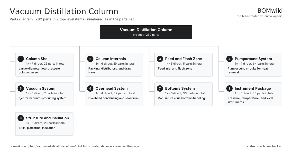
| # | Part | Qty | What it does |
|---|---|---|---|
| 1 | Column Shell 7 parts | 1× | Large-diameter low-pressure column vessel |
| 2 | Column Internals 6 parts | 1× | Packing, distributors, and draw trays |
| 3 | Feed and Flash Zone 5 parts | 1× | Feed inlet and flash zone |
| 4 | Pumparound System 4 parts | 1× | Pumparound circuits for heat removal |
| 5 | Vacuum System 6 parts | 1× | Ejector vacuum-producing system |
| 6 | Overhead System 4 parts | 1× | Overhead condensing and seal drum |
| 7 | Bottoms System 5 parts | 1× | Vacuum residue bottoms handling |
| 8 | Instrument Package 5 parts | 1× | Pressure, temperature, and level instruments |
| 9 | Structure and Insulation 6 parts | 1× | Skirt, platforms, insulation |
3D model
No 3D model yet. Have a CAD file of this? Add a 3D model. STL renders right on this page; STEP, FreeCAD, and OpenSCAD sources are welcome too (openly licensed, like all 3D models on BOMwiki).
Build & assembly graph
expand / collapse · shared sub-assemblies converge · links to related products · est. labourTap an assembly to expand/collapse · tap a part to open it · use “Open page” for any node · drag to pan, scroll to zoom.
Bill of materials for Vacuum Distillation Column
9 top-level lines · 78 rows shown · 282 parts total · indented to 3 levels| # | Item / sub-assembly | Part no. | Qty/assy | Ext. qty | Parts | Type |
|---|---|---|---|---|---|---|
| 1 | Column Shell 7 parts | vdc-column-shell | 1× | 1 | 26 | assembly |
| 1.1 | Shell Course | vdc-shell-course | 6× | 6 | · | part |
| 1.2 | Vessel Head | vdc-head | 2× | 2 | · | part |
| 1.3 | Stiffening Ring | vdc-stiffening-ring | 6× | 6 | · | part |
| 1.4 | Side-Draw Nozzle | vdc-draw-nozzle | 4× | 4 | · | part |
| 1.5 | Manway | vdc-manway | 6× | 6 | · | part |
| 1.6 | Nozzle Set | vdc-nozzle-set | 1× | 1 | · | part |
| 1.7 | Corrosion Cladding | vdc-cladding | 1× | 1 | · | part |
| 2 | Column Internals 6 parts | vdc-internals | 1× | 1 | 19 | assembly |
| 2.1 | Structured Packing | vdc-structured-packing | 4× | 4 | · | part |
| 2.2 | Liquid Distributor | vdc-liquid-distributor | 4× | 4 | · | part |
| 2.3 | Collector Tray | vdc-collector-tray | 4× | 4 | · | part |
| 2.4 | Wash Bed | vdc-wash-bed | 1× | 1 | · | part |
| 2.5 | Packing Support Grid | vdc-packing-support | 4× | 4 | · | part |
| 2.6 | Spray Header | vdc-spray-header | 2× | 2 | · | part |
| 3 | Feed and Flash Zone 5 parts | vdc-feed-flash-zone | 1× | 1 | 5 | assembly |
| 3.1 | Feed Inlet Device | vdc-feed-inlet-device | 1× | 1 | · | part |
| 3.2 | Flash Zone Baffle | vdc-flash-zone-baffle | 1× | 1 | · | part |
| 3.3 | Feed Nozzle | vdc-feed-nozzle | 1× | 1 | · | part |
| 3.4 | Transfer Line | vdc-transfer-line | 1× | 1 | · | part |
| 3.5 | Overflash Draw | vdc-overflash-draw | 1× | 1 | · | part |
| 4 | Pumparound System 4 parts | vdc-pumparound-system | 1× | 1 | 64 | assembly |
| 4.1 | Pumparound Pump 5 parts | vdc-pumparound-pump | 2× | 2 | 29 | assembly |
| 4.1.1 | Pump Casing | vdc-pump-casing | 1× | 2 | · | part |
| 4.1.2 | Pump Impeller | vdc-pump-impeller | 1× | 2 | · | part |
| 4.1.3 | Pump Mechanical Seal | vdc-pump-seal | 1× | 2 | · | part |
| 4.1.4 | Ball Bearing | ball-bearing | 2× | 4 | · | part |
| 4.1.5 | Servo Motor 4 parts + deeper › | servo-motor | 1× | 2 | 24 | assembly |
| 4.2 | Pumparound Cooler | vdc-pumparound-cooler | 2× | 2 | · | part |
| 4.3 | Pumparound Control Valve | vdc-pumparound-control-valve | 2× | 2 | · | part |
| 4.4 | Pumparound Return Distributor | vdc-pumparound-return | 2× | 2 | · | part |
| 5 | Vacuum System 6 parts | vdc-vacuum-system | 1× | 1 | 7 | assembly |
| 5.1 | First-Stage Ejector | vdc-ejector-first-stage | 1× | 1 | · | part |
| 5.2 | Second-Stage Ejector | vdc-ejector-second-stage | 1× | 1 | · | part |
| 5.3 | Third-Stage Ejector | vdc-ejector-third-stage | 1× | 1 | · | part |
| 5.4 | Intercondenser | vdc-intercondenser | 2× | 2 | · | part |
| 5.5 | Aftercondenser | vdc-aftercondenser | 1× | 1 | · | part |
| 5.6 | Motive Steam Valve | vdc-motive-steam-valve | 1× | 1 | · | part |
| 6 | Overhead System 4 parts | vdc-overhead-system | 1× | 1 | 32 | assembly |
| 6.1 | Overhead Condenser | vdc-overhead-condenser | 1× | 1 | · | part |
| 6.2 | Seal Drum | vdc-seal-drum | 1× | 1 | · | part |
| 6.3 | Overhead Pump 5 parts | vdc-overhead-pump | 1× | 1 | 29 | assembly |
| 6.3.1 | Pump Casing | vdc-pump-casing | 1× | 1 | · | part |
| 6.3.2 | Pump Impeller | vdc-pump-impeller | 1× | 1 | · | part |
| 6.3.3 | Pump Mechanical Seal | vdc-pump-seal | 1× | 1 | · | part |
| 6.3.4 | Ball Bearing | ball-bearing | 2× | 2 | · | part |
| 6.3.5 | Servo Motor 4 parts + deeper › | servo-motor | 1× | 1 | 24 | assembly |
| 6.4 | Water Jet Eductor | vdc-water-jet-eductor | 1× | 1 | · | part |
| 7 | Bottoms System 5 parts | vdc-bottoms-system | 1× | 1 | 33 | assembly |
| 7.1 | Bottoms Pump 5 parts | vdc-bottoms-pump | 1× | 1 | 29 | assembly |
| 7.1.1 | Pump Casing | vdc-pump-casing | 1× | 1 | · | part |
| 7.1.2 | Pump Impeller | vdc-pump-impeller | 1× | 1 | · | part |
| 7.1.3 | Pump Mechanical Seal | vdc-pump-seal | 1× | 1 | · | part |
| 7.1.4 | Ball Bearing | ball-bearing | 2× | 2 | · | part |
| 7.1.5 | Servo Motor 4 parts + deeper › | servo-motor | 1× | 1 | 24 | assembly |
| 7.2 | Bottoms Cooler | vdc-bottoms-cooler | 1× | 1 | · | part |
| 7.3 | Quench Injection | vdc-quench-injection | 1× | 1 | · | part |
| 7.4 | Stripping Steam Injection | vdc-stripping-steam | 1× | 1 | · | part |
| 7.5 | Bottoms Level Control Valve | vdc-bottoms-level-control | 1× | 1 | · | part |
| 8 | Instrument Package 5 parts | vdc-instrument-package | 1× | 1 | 68 | assembly |
| 8.1 | Pressure Sensor | pressure-sensor | 6× | 6 | · | part |
| 8.2 | Temperature Element | vdc-temperature-sensor | 8× | 8 | · | part |
| 8.3 | Level Instrument | vdc-level-instrument | 4× | 4 | · | part |
| 8.4 | Flow Meter | vdc-flow-meter | 6× | 6 | · | part |
| 8.5 | Control Panel 6 parts | vdc-control-panel | 1× | 1 | 44 | assembly |
| 8.5.1 | Bare PCB | pcb-bare | 2× | 2 | · | part |
| 8.5.2 | Microcontroller | mcu | 2× | 2 | · | part |
| 8.5.3 | Relay | relay | 10× | 10 | · | part |
| 8.5.4 | Power Supply | power-supply | 1× | 1 | · | part |
| 8.5.5 | Connector | connector | 28× | 28 | · | part |
| 8.5.6 | Wire Bundle | wire-bundle | 1× | 1 | · | part |
| 9 | Structure and Insulation 6 parts | vdc-structure | 1× | 1 | 28 | assembly |
| 9.1 | Support Skirt | vdc-skirt | 1× | 1 | · | part |
| 9.2 | Access Platform | vdc-platform | 6× | 6 | · | part |
| 9.3 | Caged Ladder | vdc-ladder | 3× | 3 | · | part |
| 9.4 | Thermal Insulation | vdc-insulation | 1× | 1 | · | part |
| 9.5 | Sheet Metal Panel | sheet-panel | 16× | 16 | · | part |
| 9.6 | Fastener Set | fastener-set | 1× | 1 | · | part |
Related products
same domain, ranked by shared parts Amine Gas Sweetening Unit
3,543 parts · shares 14 with this page
CO2 Injection Pump
463 parts · shares 14 with this page
Amine Gas Sweetening Unit
3,543 parts · shares 14 with this page
CO2 Injection Pump
463 parts · shares 14 with this page
 Condensate Stabilizer Column
2,234 parts · shares 14 with this page
Condensate Stabilizer Column
2,234 parts · shares 14 with this page
 Delayed Coker Drum
208 parts · shares 14 with this page
Delayed Coker Drum
208 parts · shares 14 with this page
 Drilling Mud Mixing System
135 parts · shares 14 with this page
Drilling Mud Mixing System
135 parts · shares 14 with this page
 Fired Process Heater
438 parts · shares 14 with this page
Fired Process Heater
438 parts · shares 14 with this page
Sourcing: possible vendors
Browse the supplier directory → Prices, MOQ, and lead times are algorithmic estimates, not quotes, and not claims about these companies. Company mappings are curated by keyword; est. price band $10k–$50M. How estimates work| Vendor | HQ | Specialty | MOQ | Lead time |
|---|---|---|---|---|
|
🇺🇸SLB
slb.com ↗
|
Houston, US | Oilfield services & equipment | made to order | 24–48 wks |
| halliburton.com ↗ | Houston, US | Oilfield services | made to order | 24–48 wks |
| bakerhughes.com ↗ | Houston, US | Energy technology | made to order | 24–48 wks |
|
🇺🇸NOV
nov.com ↗
|
Houston, US | Drilling equipment | made to order | 24–48 wks |
| technipfmc.com ↗ | London, GB | Subsea & surface systems | made to order | 24–48 wks |
940-word article