Mudline Suspension System
ProductOverview
A mudline suspension system supports the weight of a well's casing strings at the seabed rather than at a surface wellhead. It is used on jack-up rigs and fixed platforms in shallow water, where a well is often drilled by a mobile jack-up, suspended at the mudline, and later tied back to a permanent platform. Each casing string the driller runs, the 30 in Conductor Hanger conductor, the surface casing, the intermediate string and the production string, lands its weight into a nested set of hangers sitting just above the seabed. This lets the driller walk away from the well with the casing fully supported and protected, then return months or years later to complete it through a Tieback Adapter Set connection.
The system exists because in shallow water there is no subsea tree and no riser tensioner carrying the casing. The casing has to hang from something fixed and structural at the seabed, and that something is the mudline suspension stack. The whole assembly is built around the Landing Ring Assembly, a forged ring welded into the conductor that carries the combined weight of every string above it.
How it works
The conductor, usually 30 in, is driven or drilled and cemented first. The Landing Base Ring is built into the top of that conductor and provides the load shoulder for everything that follows. Each subsequent casing string is run with a hanger made up directly to the top joint of casing. As the string is lowered, its Running and Retrieving Tools guide the hanger down through the bores of the strings already set, using the Guide Funnel and Alignment Key to orient it. The hanger lands on the bowl of the string immediately outside it, so the hangers nest one inside the next like a telescope.
Once a hanger lands, its weight is transferred through a split load ring onto the bowl below, and that load passes down the stack until it reaches the conductor and the landing ring. The driller then sets the lock screws and the seals before drilling ahead for the next hole section. Because the hangers are concentric, the annulus between each pair of strings has to be sealed independently, which is the job of the Seal Assembly Set.
Casing hangers and load transfer
The hanger stack is the core of the system. Each hanger has three working features: a mandrel made up to its casing, a load ring that lands it on the string below, and a bowl that will receive the next string in. The 20 in Surface Casing Hanger surface hanger lands inside the conductor hanger bowl, the 13-3/8 in Intermediate Hanger intermediate hanger lands inside the surface bowl, and the 9-5/8 in Production Hanger production hanger lands inside the intermediate bowl. The innermost production hanger has no bowl because nothing lands inside it, but it does carry a back pressure port so cement returns can flow past it during the production casing cement job.
Load transfer is the design driver. A combined hanging weight of 500 to 2,000 short tons has to pass from the casing, through the split load rings, into the bowls and finally into the conductor and the seabed. The mandrels and bowls are forged from AISI 4130 or 4140 low-alloy steel and heat treated to handle that load with margin. The split load rings spread the bearing stress around the full circumference of each bowl so no single point is overloaded.
Seals and lockdown
Each annulus between two concentric strings is a potential pressure path, so every hanger interface is sealed twice. The primary seal is a Metal-to-Metal Seal Ring, an energized metal-to-metal ring of Inconel 718 that gives a gas-tight barrier rated to the full working pressure of 5,000 to 15,000 psi. Behind it sits an Elastomer Packoff in HNBR or a similar compound as a backup and as a low-pressure seal during installation. A seal energizer ring drives the metal seal home, and a test port at each interface lets the crew pressure test the seal before drilling ahead.
Pressure and thermal cycling try to push the hangers back up, so each one is locked down. The Lockdown and Hold-Down uses 12 to 16 radial lock screws per hanger, run inward through the body to bear on the mandrel. Each lock screw penetration is sealed with its own gland packing and protected by a cap, because a leaking lock screw is a leak path to the annulus. The lock screws are made of 17-4 PH stainless for strength and corrosion resistance, and on sour wells the whole assembly is built to NACE MR0175.
Running and retrieval tools
Nothing in the system is set by hand: every component runs on drill pipe. The Running Tool Body carries a collet that grips the hanger profile, a J-slot that sets and releases the tool with pipe rotation, and an orientation sub that times the tool to the alignment keys. After a string is hung, a wear bushing is run to protect the seal bores from the drill string during the next hole section, and it is later pulled with the Retrieving Tool. A dedicated seal test tool isolates each annulus and pressures it up to confirm the metal seal before the rig moves on.
When the well is suspended, an Abandonment and Caps cap is run to seal the well at the mudline and a corrosion cap excludes seawater from the dormant bores. To complete the well later, the caps come off and the Tieback Adapter Set adapters stab into each hanger, extending the strings up to the platform wellhead.
Materials and applications
Bodies and load-bearing components are low-alloy steel, typically AISI 4130 or 4140, heat treated for the rated load and pressure. Seals are Inconel 718 backed by HNBR elastomer, and lock screws are 17-4 PH. Sour service wells follow API 17D, API 6A and NACE MR0175, with material hardness controlled to resist sulfide stress cracking. Mudline suspension systems are standard on jack-up exploration and appraisal wells, on fixed-platform development wells in water depths up to roughly 400 ft, and anywhere a well must be drilled by one rig and completed later from a fixed structure.
Mudline Suspension System parts and their functions
8 top-level parts · 246 parts in total · full bill of materials below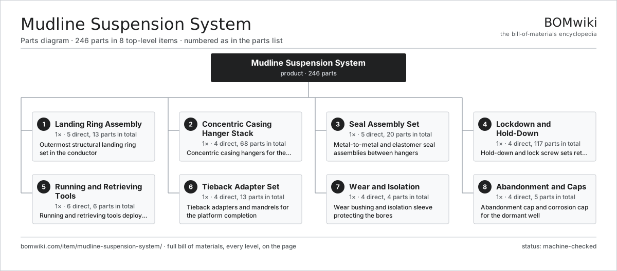
| # | Part | Qty | What it does |
|---|---|---|---|
| 1 | Landing Ring Assembly 5 parts | 1× | Outermost structural landing ring set in the conductor |
| 2 | Concentric Casing Hanger Stack 4 parts | 1× | Concentric casing hangers for the multiple casing strings |
| 3 | Seal Assembly Set 5 parts | 1× | Metal-to-metal and elastomer seal assemblies between hangers |
| 4 | Lockdown and Hold-Down 4 parts | 1× | Hold-down and lock screw sets retaining each hanger |
| 5 | Running and Retrieving Tools 6 parts | 1× | Running and retrieving tools deployed on drill pipe |
| 6 | Tieback Adapter Set 4 parts | 1× | Tieback adapters and mandrels for the platform completion |
| 7 | Wear and Isolation 4 parts | 1× | Wear bushing and isolation sleeve protecting the bores |
| 8 | Abandonment and Caps 4 parts | 1× | Abandonment cap and corrosion cap for the dormant well |
3D model
No 3D model yet. Have a CAD file of this? Add a 3D model. STL renders right on this page; STEP, FreeCAD, and OpenSCAD sources are welcome too (openly licensed, like all 3D models on BOMwiki).
Build & assembly graph
expand / collapse · shared sub-assemblies converge · links to related products · est. labourTap an assembly to expand/collapse · tap a part to open it · use “Open page” for any node · drag to pan, scroll to zoom.
Bill of materials for Mudline Suspension System
8 top-level lines · 60 rows shown · 246 parts total · indented to 3 levels| # | Item / sub-assembly | Part no. | Qty/assy | Ext. qty | Parts | Type |
|---|---|---|---|---|---|---|
| 1 | Landing Ring Assembly 5 parts | mudline-suspension-system-landing-ring | 1× | 1 | 13 | assembly |
| 1.1 | Landing Base Ring | mudline-suspension-system-base-ring | 1× | 1 | · | part |
| 1.2 | Load Shoulder | mudline-suspension-system-load-shoulder | 1× | 1 | · | part |
| 1.3 | Guide Funnel | mudline-suspension-system-guide-funnel | 1× | 1 | · | part |
| 1.4 | Alignment Key | mudline-suspension-system-alignment-key | 4× | 4 | · | part |
| 1.5 | Anti-Rotation Lug | mudline-suspension-system-anti-rotation-lug | 6× | 6 | · | part |
| 2 | Concentric Casing Hanger Stack 4 parts | mudline-suspension-system-hanger-stack | 1× | 1 | 68 | assembly |
| 2.1 | 30 in Conductor Hanger 4 parts | mudline-suspension-system-hanger-30in | 1× | 1 | 19 | assembly |
| 2.1.1 | 30 in Hanger Mandrel | mudline-suspension-system-mandrel-30in | 1× | 1 | · | part |
| 2.1.2 | 30 in Hanger Bowl | mudline-suspension-system-bowl-30in | 1× | 1 | · | part |
| 2.1.3 | 30 in Load Ring | mudline-suspension-system-load-ring-30in | 1× | 1 | · | part |
| 2.1.4 | Radial Lock Screw | mudline-suspension-system-lock-screw | 16× | 16 | · | part |
| 2.2 | 20 in Surface Casing Hanger 4 parts | mudline-suspension-system-hanger-20in | 1× | 1 | 19 | assembly |
| 2.2.1 | 20 in Hanger Mandrel | mudline-suspension-system-mandrel-20in | 1× | 1 | · | part |
| 2.2.2 | 20 in Hanger Bowl | mudline-suspension-system-bowl-20in | 1× | 1 | · | part |
| 2.2.3 | 20 in Load Ring | mudline-suspension-system-load-ring-20in | 1× | 1 | · | part |
| 2.2.4 | Radial Lock Screw | mudline-suspension-system-lock-screw | 16× | 16 | · | part |
| 2.3 | 13-3/8 in Intermediate Hanger 4 parts | mudline-suspension-system-hanger-133in | 1× | 1 | 15 | assembly |
| 2.3.1 | 13-3/8 in Hanger Mandrel | mudline-suspension-system-mandrel-133in | 1× | 1 | · | part |
| 2.3.2 | 13-3/8 in Hanger Bowl | mudline-suspension-system-bowl-133in | 1× | 1 | · | part |
| 2.3.3 | 13-3/8 in Load Ring | mudline-suspension-system-load-ring-133in | 1× | 1 | · | part |
| 2.3.4 | Radial Lock Screw | mudline-suspension-system-lock-screw | 12× | 12 | · | part |
| 2.4 | 9-5/8 in Production Hanger 4 parts | mudline-suspension-system-hanger-95in | 1× | 1 | 15 | assembly |
| 2.4.1 | 9-5/8 in Hanger Mandrel | mudline-suspension-system-mandrel-95in | 1× | 1 | · | part |
| 2.4.2 | 9-5/8 in Load Ring | mudline-suspension-system-load-ring-95in | 1× | 1 | · | part |
| 2.4.3 | Back Pressure Port | mudline-suspension-system-back-pressure-port | 1× | 1 | · | part |
| 2.4.4 | Radial Lock Screw | mudline-suspension-system-lock-screw | 12× | 12 | · | part |
| 3 | Seal Assembly Set 5 parts | mudline-suspension-system-seal-system | 1× | 1 | 20 | assembly |
| 3.1 | Metal-to-Metal Seal Ring | mudline-suspension-system-metal-seal | 4× | 4 | · | part |
| 3.2 | Elastomer Packoff | mudline-suspension-system-elastomer-seal | 4× | 4 | · | part |
| 3.3 | Seal Energizer Ring | mudline-suspension-system-seal-energizer | 4× | 4 | · | part |
| 3.4 | Seal Test Port | mudline-suspension-system-seal-test-port | 4× | 4 | · | part |
| 3.5 | O-Ring Set | oring-set | 4× | 4 | · | part |
| 4 | Lockdown and Hold-Down 4 parts | mudline-suspension-system-lockdown | 1× | 1 | 117 | assembly |
| 4.1 | Hold-Down Ring | mudline-suspension-system-hold-down-ring | 4× | 4 | · | part |
| 4.2 | Lock Screw Gland | mudline-suspension-system-lock-screw-gland | 56× | 56 | · | part |
| 4.3 | Lock Screw Cap | mudline-suspension-system-lock-screw-cap | 56× | 56 | · | part |
| 4.4 | Fastener Set | fastener-set | 1× | 1 | · | part |
| 5 | Running and Retrieving Tools 6 parts | mudline-suspension-system-running-tools | 1× | 1 | 6 | assembly |
| 5.1 | Running Tool Body | mudline-suspension-system-running-tool-body | 1× | 1 | · | part |
| 5.2 | Collet | mudline-suspension-system-collet | 1× | 1 | · | part |
| 5.3 | J-Slot Mechanism | mudline-suspension-system-j-slot | 1× | 1 | · | part |
| 5.4 | Retrieving Tool | mudline-suspension-system-retrieving-tool | 1× | 1 | · | part |
| 5.5 | Seal Test Tool | mudline-suspension-system-test-tool | 1× | 1 | · | part |
| 5.6 | Orientation Sub | mudline-suspension-system-orientation-sub | 1× | 1 | · | part |
| 6 | Tieback Adapter Set 4 parts | mudline-suspension-system-tieback | 1× | 1 | 13 | assembly |
| 6.1 | Tieback Adapter | mudline-suspension-system-tieback-adapter | 4× | 4 | · | part |
| 6.2 | Tieback Mandrel | mudline-suspension-system-tieback-mandrel | 4× | 4 | · | part |
| 6.3 | Tieback Seal | mudline-suspension-system-tieback-seal | 4× | 4 | · | part |
| 6.4 | Connector | connector | 1× | 1 | · | part |
| 7 | Wear and Isolation 4 parts | mudline-suspension-system-wear-isolation | 1× | 1 | 4 | assembly |
| 7.1 | Wear Bushing | mudline-suspension-system-wear-bushing | 1× | 1 | · | part |
| 7.2 | Isolation Sleeve | mudline-suspension-system-isolation-sleeve | 1× | 1 | · | part |
| 7.3 | Bushing Retainer | mudline-suspension-system-bushing-retainer | 1× | 1 | · | part |
| 7.4 | Bore Protector | mudline-suspension-system-nominal-bore-protector | 1× | 1 | · | part |
| 8 | Abandonment and Caps 4 parts | mudline-suspension-system-abandonment | 1× | 1 | 5 | assembly |
| 8.1 | Abandonment Cap | mudline-suspension-system-abandonment-cap | 1× | 1 | · | part |
| 8.2 | Corrosion Cap | mudline-suspension-system-corrosion-cap | 1× | 1 | · | part |
| 8.3 | Cap Seal | mudline-suspension-system-cap-seal | 2× | 2 | · | part |
| 8.4 | Cap Handling Tool | mudline-suspension-system-cap-handling-tool | 1× | 1 | · | part |
Sourcing: possible vendors
Browse the supplier directory → Prices, MOQ, and lead times are algorithmic estimates, not quotes, and not claims about these companies. Company mappings are curated by keyword; est. price band $10k–$50M. How estimates work| Vendor | HQ | Specialty | MOQ | Lead time |
|---|---|---|---|---|
|
🇺🇸SLB
slb.com ↗
|
Houston, US | Oilfield services & equipment | made to order | 24–48 wks |
| halliburton.com ↗ | Houston, US | Oilfield services | made to order | 24–48 wks |
| bakerhughes.com ↗ | Houston, US | Energy technology | made to order | 24–48 wks |
|
🇺🇸NOV
nov.com ↗
|
Houston, US | Drilling equipment | made to order | 24–48 wks |
| technipfmc.com ↗ | London, GB | Subsea & surface systems | made to order | 24–48 wks |
1,080-word article