Gas Engine Driven Compressor
ProductOverview
A gas engine driven compressor of the integral type combines an engine and a compressor on a single crankshaft inside one frame. Vertical power cylinders fire to turn the crank, and horizontal compressor cylinders hang off the same crank to do the compression. This integral layout is the classic pipeline-station machine: large, slow-turning, and built to run for decades boosting gas pressure along a transmission line. Because engine and compressor share the crankshaft, there is no coupling, no separate driver foundation, and one set of running gear to maintain.
The machine boosts pipeline pressure that has dropped through friction over long distances. Stations along a pipeline each add back the pressure the gas lost, keeping the flow moving. The integral compressor handles the high pressure and large flow of mainline service at low speed, which gives long valve and ring life.
Integral frame
The defining feature is the Integral Frame. A single large Frame Casting houses one Crankshaft running in five or more Main Bearing journals. Some throws on that crank drive the engine pistons through Connecting Rod links, and other throws drive the horizontal compressor pistons through Crosshead guides. A heavy Flywheel stores energy between firing strokes and compression strokes, smoothing the combined torque so the crankshaft turns evenly. Building both functions onto one crank is what makes the machine compact for its power and removes the alignment problems of a separate engine and compressor.
Power section
The Power Section is the engine half. Vertical Power Cylinder units each contain a Power Piston capped by a Cylinder Head that carries the Intake Valve and Exhaust Valve poppets and the spark plug. The cylinders fire in sequence to turn the crank. A pair of Turbocharger units, driven by the exhaust, scavenge the burned gas and pack fresh charge into the cylinders, which raises power without a larger engine. Running at 300 to 450 rpm, far slower than a vehicle engine, the power section trades speed for durability.
Compression section
The Compression Section is the compressor half. Horizontal Compressor Cylinder units each hold a double-acting Compressor Piston driven by a Piston Rod through the crosshead. As the piston moves, the Suction Valve admits low-pressure pipeline gas and the Discharge Valve releases it at the boosted pressure, compressing on both sides of the piston. The piston seals against the bore with Piston Ring elements, and a Packing Case seals the rod where it leaves the cylinder. Double-acting cylinders compress on every stroke in both directions, doubling the gas moved per revolution.
Fuel, ignition and aspiration
The Fuel System burns a slipstream of the pipeline gas the machine is compressing. A Fuel Regulator drops it to engine supply pressure, a Fuel Filter cleans it, and a Air-Fuel Mixer mixer blends it with air filtered by the Air Filter, with a Fuel Valve admitting metered fuel to each cylinder. The Ignition System fires a Spark Plug in each cylinder through a Ignition Coil, with a digital Ignition Module setting timing from crank position and load. Per-cylinder digital ignition lets the engine run lean and clean enough to meet emissions limits at a pipeline station.
Cooling and lubrication
Two cooling duties run together in the Cooling System. A Water Pump circulates jacket water through the engine to a Radiator, with a Thermostat holding temperature and Cooler Fan units pulling air through the core. Separately, a pair of Aftercooler exchangers cool the compressed gas between and after stages so it leaves at a sensible temperature. The Lubrication System feeds the bearings from a Oil Pump through a Oil Filter and Oil Cooler, while a set of Cylinder Lubricator units force-feed measured oil into each compressor bore and packing, which is the only way the sliding seals survive at these pressures.
Control, protection and use
The Control System runs the whole machine. A Unit Controller manages fuel, ignition timing and capacity control, working with a Governor Actuator that trims fuel to hold speed under changing pipeline load. Process pressure transmitters and a set of Vibration Switch units feed the protection logic, so the unit shuts down on high temperature, low oil pressure or excess vibration before it damages itself.
Integral machines are sized from a few hundred to several thousand horsepower, matched to the station's flow and the pressure boost the pipeline needs. Their low speed and one-piece running gear give very long service intervals, which is why many have run at the same compressor station for forty or fifty years. Operators value them for that longevity and for burning the very gas they move, so the station needs no separate fuel supply.
Gas Engine Driven Compressor parts and their functions
8 top-level parts · 217 parts in total · full bill of materials below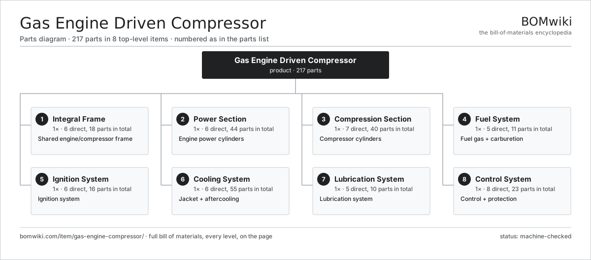
| # | Part | Qty | What it does |
|---|---|---|---|
| 1 | Integral Frame 6 parts | 1× | Shared engine/compressor frame |
| 2 | Power Section 6 parts | 1× | Engine power cylinders |
| 3 | Compression Section 7 parts | 1× | Compressor cylinders |
| 4 | Fuel System 5 parts | 1× | Fuel gas + carburetion |
| 5 | Ignition System 6 parts | 1× | Ignition system |
| 6 | Cooling System 6 parts | 1× | Jacket + aftercooling |
| 7 | Lubrication System 5 parts | 1× | Lubrication system |
| 8 | Control System 8 parts | 1× | Control + protection |
3D model
No 3D model yet. Have a CAD file of this? Add a 3D model. STL renders right on this page; STEP, FreeCAD, and OpenSCAD sources are welcome too (openly licensed, like all 3D models on BOMwiki).
Build & assembly graph
expand / collapse · shared sub-assemblies converge · links to related products · est. labourTap an assembly to expand/collapse · tap a part to open it · use “Open page” for any node · drag to pan, scroll to zoom.
Bill of materials for Gas Engine Driven Compressor
8 top-level lines · 61 rows shown · 217 parts total · indented to 3 levels| # | Item / sub-assembly | Part no. | Qty/assy | Ext. qty | Parts | Type |
|---|---|---|---|---|---|---|
| 1 | Integral Frame 6 parts | gec-integral-frame | 1× | 1 | 18 | assembly |
| 1.1 | Frame Casting | gec-frame-casting | 1× | 1 | · | part |
| 1.2 | Crankshaft | gec-crankshaft | 1× | 1 | · | part |
| 1.3 | Main Bearing | gec-main-bearing | 5× | 5 | · | part |
| 1.4 | Connecting Rod | gec-connecting-rod | 6× | 6 | · | part |
| 1.5 | Crosshead | gec-crosshead | 4× | 4 | · | part |
| 1.6 | Flywheel | gec-flywheel | 1× | 1 | · | part |
| 2 | Power Section 6 parts | gec-power-section | 1× | 1 | 44 | assembly |
| 2.1 | Power Cylinder | gec-power-cylinder | 6× | 6 | · | part |
| 2.2 | Power Piston | gec-power-piston | 6× | 6 | · | part |
| 2.3 | Cylinder Head | gec-cylinder-head | 6× | 6 | · | part |
| 2.4 | Intake Valve | gec-intake-valve | 12× | 12 | · | part |
| 2.5 | Exhaust Valve | gec-exhaust-valve | 12× | 12 | · | part |
| 2.6 | Turbocharger | gec-turbocharger | 2× | 2 | · | part |
| 3 | Compression Section 7 parts | gec-compression-section | 1× | 1 | 40 | assembly |
| 3.1 | Compressor Cylinder | gec-comp-cylinder | 4× | 4 | · | part |
| 3.2 | Compressor Piston | gec-comp-piston | 4× | 4 | · | part |
| 3.3 | Piston Rod | gec-piston-rod | 4× | 4 | · | part |
| 3.4 | Suction Valve | gec-suction-valve | 8× | 8 | · | part |
| 3.5 | Discharge Valve | gec-discharge-valve | 8× | 8 | · | part |
| 3.6 | Piston Ring | gec-piston-ring | 8× | 8 | · | part |
| 3.7 | Packing Case | gec-packing-case | 4× | 4 | · | part |
| 4 | Fuel System 5 parts | gec-fuel-system | 1× | 1 | 11 | assembly |
| 4.1 | Fuel Regulator | gec-fuel-regulator | 1× | 1 | · | part |
| 4.2 | Fuel Filter | gec-fuel-filter | 1× | 1 | · | part |
| 4.3 | Air-Fuel Mixer | gec-carburetor | 1× | 1 | · | part |
| 4.4 | Fuel Valve | gec-fuel-valve | 6× | 6 | · | part |
| 4.5 | Air Filter | gec-air-filter | 2× | 2 | · | part |
| 5 | Ignition System 6 parts | gec-ignition-system | 1× | 1 | 16 | assembly |
| 5.1 | Spark Plug | gec-spark-plug | 6× | 6 | · | part |
| 5.2 | Ignition Coil | gec-ignition-coil | 6× | 6 | · | part |
| 5.3 | Ignition Module | gec-ignition-module | 1× | 1 | · | part |
| 5.4 | Bare PCB | pcb-bare | 1× | 1 | · | part |
| 5.5 | Microcontroller | mcu | 1× | 1 | · | part |
| 5.6 | Wire Bundle | wire-bundle | 1× | 1 | · | part |
| 6 | Cooling System 6 parts | gec-cooling-system | 1× | 1 | 55 | assembly |
| 6.1 | Water Pump | gec-water-pump | 1× | 1 | · | part |
| 6.2 | Radiator | gec-radiator | 1× | 1 | · | part |
| 6.3 | Aftercooler | gec-aftercooler | 2× | 2 | · | part |
| 6.4 | Thermostat | gec-thermostat | 1× | 1 | · | part |
| 6.5 | Cooler Fan | gec-cooler-fan | 2× | 2 | · | part |
| 6.6 | Servo Motor 4 parts | servo-motor | 2× | 2 | 24 | assembly |
| 6.6.1 | Stator Assembly 3 parts + deeper › | stator-assembly | 1× | 2 | 3 | assembly |
| 6.6.2 | Rotor Assembly 4 parts + deeper › | rotor-assembly | 1× | 2 | 19 | assembly |
| 6.6.3 | Encoder | encoder | 1× | 2 | · | part |
| 6.6.4 | Motor Housing | motor-housing | 1× | 2 | · | part |
| 7 | Lubrication System 5 parts | gec-lube-system | 1× | 1 | 10 | assembly |
| 7.1 | Oil Pump | gec-oil-pump | 1× | 1 | · | part |
| 7.2 | Oil Filter | gec-oil-filter | 2× | 2 | · | part |
| 7.3 | Oil Cooler | gec-oil-cooler | 1× | 1 | · | part |
| 7.4 | Cylinder Lubricator | gec-cylinder-lubricator | 4× | 4 | · | part |
| 7.5 | Pressure Sensor | pressure-sensor | 2× | 2 | · | part |
| 8 | Control System 8 parts | gec-control-system | 1× | 1 | 23 | assembly |
| 8.1 | Unit Controller | gec-controller | 1× | 1 | · | part |
| 8.2 | LCD Panel | lcd-panel | 1× | 1 | · | part |
| 8.3 | Power Supply | power-supply | 1× | 1 | · | part |
| 8.4 | Governor Actuator | gec-governor-actuator | 1× | 1 | · | part |
| 8.5 | Pressure Sensor | pressure-sensor | 6× | 6 | · | part |
| 8.6 | Vibration Switch | gec-vibration-switch | 4× | 4 | · | part |
| 8.7 | Relay | relay | 8× | 8 | · | part |
| 8.8 | Wire Bundle | wire-bundle | 1× | 1 | · | part |
Related products
same domain, ranked by shared parts Drilling Mud Mixing System
135 parts · shares 14 with this page
Drilling Mud Mixing System
135 parts · shares 14 with this page
 Oilwell Cementing Unit
902 parts · shares 14 with this page
Oilwell Cementing Unit
902 parts · shares 14 with this page
 Reciprocating Gas Compressor Package
187 parts · shares 14 with this page
Reciprocating Gas Compressor Package
187 parts · shares 14 with this page
 Wireline Logging Unit
189 parts · shares 14 with this page
Wireline Logging Unit
189 parts · shares 14 with this page
 Amine Gas Sweetening Unit
3,543 parts · shares 13 with this page
Amine Gas Sweetening Unit
3,543 parts · shares 13 with this page
Sourcing: possible vendors
Browse the supplier directory → Prices, MOQ, and lead times are algorithmic estimates, not quotes, and not claims about these companies. Company mappings are curated by keyword; est. price band $10k–$50M. How estimates work| Vendor | HQ | Specialty | MOQ | Lead time |
|---|---|---|---|---|
|
🇺🇸SLB
slb.com ↗
|
Houston, US | Oilfield services & equipment | made to order | 24–48 wks |
| halliburton.com ↗ | Houston, US | Oilfield services | made to order | 24–48 wks |
| bakerhughes.com ↗ | Houston, US | Energy technology | made to order | 24–48 wks |
|
🇺🇸NOV
nov.com ↗
|
Houston, US | Drilling equipment | made to order | 24–48 wks |
| technipfmc.com ↗ | London, GB | Subsea & surface systems | made to order | 24–48 wks |
821-word article