Amine Gas Sweetening Unit
ProductOverview
An amine gas sweetening unit removes the acid gases hydrogen sulfide and carbon dioxide from natural gas or refinery gas. Raw gas from many fields is sour, carrying enough H2S to be lethal and corrosive and enough CO2 to lower its heating value, so it cannot enter a sales pipeline until it is sweetened. The unit does this by washing the gas with a circulating aqueous amine solution that chemically absorbs the acid gases, then heats the loaded solution to drive them back off, regenerating the amine for another pass. The same solvent cycles continuously, so the unit is defined by its two columns: the Absorber Column that picks up acid gas and the Regenerator Column that releases it.
The choice of amine sets the unit's behavior. Monoethanolamine is aggressive and removes both H2S and CO2 to low levels but degrades and corrodes readily. Methyldiethanolamine, often formulated with activators, can be tuned to remove H2S selectively while slipping much of the CO2, which saves energy where only H2S needs to go. The unit handles 5 to 500 MMSCFD with treated H2S driven below the 4 ppmv pipeline limit.
Absorption
Sour gas enters the bottom of the Absorber Column through the Inlet Gas Distributor and rises through a stack of Valve Tray contacting stages. Lean amine, cooled and pumped to absorber pressure, enters near the top and flows down across each tray. On every tray the gas bubbles up through the liquid held by the Tray Valve Cap caps, and the amine absorbs H2S and CO2. The reactions are exothermic, so the column runs warm, and the gas leaves the top sweet. A Mist Eliminator catches entrained amine droplets so the treated gas does not carry solvent into the pipeline.
Absorber pressure is high, typically 300 to 1,200 psig, because the high partial pressure of the acid gases drives them into solution. The richer the amine leaves the bottom, the less solution must be circulated, but loading it too heavily causes corrosion and incomplete pickup, so the circulation rate and amine strength are balanced against the inlet acid gas load.
Flashing and heat recovery
The rich amine leaving the absorber bottom is at high pressure and carries dissolved hydrocarbon gas. It first drops into the Rich Amine Flash Tank, where the pressure is reduced and the light hydrocarbons flash off through a Flash Gas Valve rather than carrying into the still, where they would cause foaming. A Hydrocarbon Skimmer removes any free hydrocarbon liquid that separates on top of the amine.
The flashed rich amine then passes through the Lean/Rich Exchanger, the most important energy device in the unit. Hot lean amine returning from the regenerator preheats the cold rich amine on its way to the still, recovering heat that would otherwise be supplied by the reboiler and rejected by the cooler. A well-designed cross exchanger cuts the unit's energy use substantially, which is why it carries a large Tube Bundle.
Regeneration
Preheated rich amine enters the Regenerator Column, a stripping still. At the bottom, the Steam Reboiler boils a portion of the amine using steam, generating water vapor that rises through the trays and strips the absorbed H2S and CO2 out of the descending liquid. The acid gases and water vapor leave the top of the still, while regenerated lean amine collects in the bottom and returns through the Lean/Rich Exchanger to the absorber. Reboiler heat duty, expressed per gallon of amine circulated, is the dominant operating cost.
The still overhead passes through the Overhead Condenser, which condenses the water vapor. The mixture drops into the Reflux System, where the Reflux Accumulator Drum separates condensed water from the concentrated acid gas. The Reflux Pump returns the water as reflux to the still to maintain the water balance, and the acid gas, now mostly H2S and CO2, goes to a sulfur recovery unit or a flare.
Circulation and solution care
The Amine Circulation system keeps the solvent moving and clean. A Booster Pump feeds the High-Pressure Charge Pump, a multistage unit that lifts lean amine back to absorber pressure. Solution cleanliness is critical because iron sulfide particles, hydrocarbon contamination and amine degradation products all promote foaming and corrosion. A Mechanical Amine Filter removes particulate, and a slipstream through the Activated Carbon Filter adsorbs the surfactants and heat-stable salts that cause foaming. The Amine Surge Tank holds the loop inventory and absorbs volume swings.
Cooling, control and materials
The Cooling System uses the Lean Amine Air Cooler to drop the regenerated amine to absorber temperature, since cooler amine absorbs more acid gas. Air coolers with a Air Cooler Fan are common where water is scarce. The Control System runs the unit through a DCS that holds amine circulation, reboiler duty and column levels at the values that meet the H2S sales spec, with a H2S Analyzer confirming the treated gas, RTD Temperature Probe elements on the columns and exchangers, and Pressure Sensor feedback on the loops.
Materials reflect the corrosive, hot service. Vessels are carbon steel to ASME Section VIII, but the absorber and still internals, the hot lean piping and the reboiler tubes use stainless grades because hot rich amine attacks carbon steel. Wetted pump parts and trays are stainless, and the whole unit follows ASME B31.3 for process piping and API 526 for the relief valves on the Process Piping Skid that protect the vessels against overpressure.
Amine Gas Sweetening Unit parts and their functions
9 top-level parts · 3,543 parts in total · full bill of materials below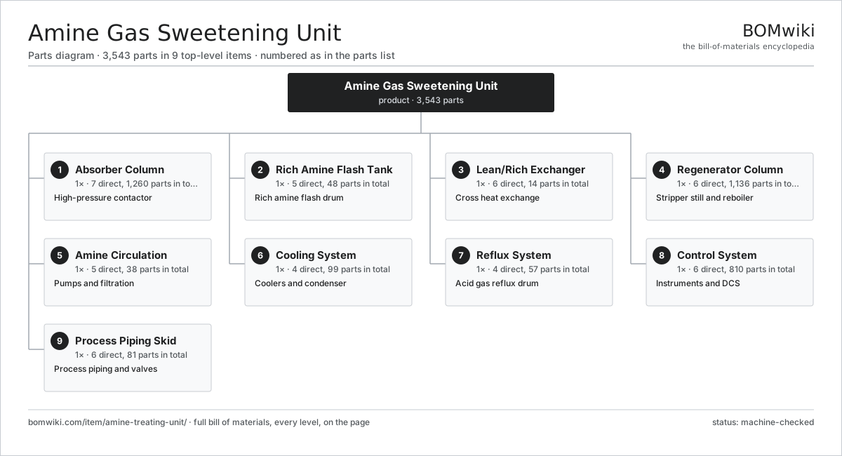
| # | Part | Qty | What it does |
|---|---|---|---|
| 1 | Absorber Column 7 parts | 1× | High-pressure contactor |
| 2 | Rich Amine Flash Tank 5 parts | 1× | Rich amine flash drum |
| 3 | Lean/Rich Exchanger 6 parts | 1× | Cross heat exchange |
| 4 | Regenerator Column 6 parts | 1× | Stripper still and reboiler |
| 5 | Amine Circulation 5 parts | 1× | Pumps and filtration |
| 6 | Cooling System 4 parts | 1× | Coolers and condenser |
| 7 | Reflux System 4 parts | 1× | Acid gas reflux drum |
| 8 | Control System 6 parts | 1× | Instruments and DCS |
| 9 | Process Piping Skid 6 parts | 1× | Process piping and valves |
3D model
No 3D model yet. Have a CAD file of this? Add a 3D model. STL renders right on this page; STEP, FreeCAD, and OpenSCAD sources are welcome too (openly licensed, like all 3D models on BOMwiki).
Build & assembly graph
expand / collapse · shared sub-assemblies converge · links to related products · est. labourTap an assembly to expand/collapse · tap a part to open it · use “Open page” for any node · drag to pan, scroll to zoom.
Bill of materials for Amine Gas Sweetening Unit
9 top-level lines · 109 rows shown · 3,543 parts total · indented to 3 levels| # | Item / sub-assembly | Part no. | Qty/assy | Ext. qty | Parts | Type |
|---|---|---|---|---|---|---|
| 1 | Absorber Column 7 parts | atu-absorber-column | 1× | 1 | 1,260 | assembly |
| 1.1 | Column Shell | atu-column-shell | 1× | 1 | · | part |
| 1.2 | Valve Tray 3 parts | atu-tray | 20× | 20 | 62 | assembly |
| 1.2.1 | Tray Deck | atu-tray-deck | 1× | 20 | · | part |
| 1.2.2 | Tray Valve Cap | atu-tray-valve | 60× | 1,200 | · | part |
| 1.2.3 | Downcomer | atu-downcomer | 1× | 20 | · | part |
| 1.3 | Mist Eliminator | atu-mist-eliminator | 1× | 1 | · | part |
| 1.4 | Inlet Gas Distributor | atu-inlet-distributor | 1× | 1 | · | part |
| 1.5 | Column Internals Support | atu-column-internals | 1× | 1 | · | part |
| 1.6 | Manway | atu-manway | 4× | 4 | · | part |
| 1.7 | Process Nozzle | atu-nozzle | 12× | 12 | · | part |
| 2 | Rich Amine Flash Tank 5 parts | atu-flash-tank | 1× | 1 | 48 | assembly |
| 2.1 | Flash Vessel | atu-flash-vessel | 1× | 1 | · | part |
| 2.2 | Level Control Loop 2 parts | atu-level-control | 1× | 1 | 44 | assembly |
| 2.2.1 | Level Transmitter 4 parts + deeper › | atu-level-transmitter | 1× | 1 | 43 | assembly |
| 2.2.2 | Level Control Valve | atu-level-valve | 1× | 1 | · | part |
| 2.3 | Hydrocarbon Skimmer | atu-skimmer | 1× | 1 | · | part |
| 2.4 | Flash Gas Valve | atu-flash-gas-valve | 1× | 1 | · | part |
| 2.5 | Pressure Sensor | pressure-sensor | 1× | 1 | · | part |
| 3 | Lean/Rich Exchanger 6 parts | atu-lean-rich-exchanger | 1× | 1 | 14 | assembly |
| 3.1 | Exchanger Shell | atu-exchanger-shell | 1× | 1 | · | part |
| 3.2 | Tube Bundle | atu-tube-bundle | 1× | 1 | · | part |
| 3.3 | Tubesheet | atu-tubesheet | 2× | 2 | · | part |
| 3.4 | Baffle Plate | atu-baffle | 8× | 8 | · | part |
| 3.5 | O-Ring Set | oring-set | 1× | 1 | · | part |
| 3.6 | Fastener Set | fastener-set | 1× | 1 | · | part |
| 4 | Regenerator Column 6 parts | atu-regenerator-column | 1× | 1 | 1,136 | assembly |
| 4.1 | Still Shell | atu-still-shell | 1× | 1 | · | part |
| 4.2 | Valve Tray 3 parts | atu-tray | 18× | 18 | 62 | assembly |
| 4.2.1 | Tray Deck | atu-tray-deck | 1× | 18 | · | part |
| 4.2.2 | Tray Valve Cap | atu-tray-valve | 60× | 1,080 | · | part |
| 4.2.3 | Downcomer | atu-downcomer | 1× | 18 | · | part |
| 4.3 | Steam Reboiler 4 parts | atu-reboiler | 1× | 1 | 5 | assembly |
| 4.3.1 | Reboiler Shell | atu-reboiler-shell | 1× | 1 | · | part |
| 4.3.2 | Tube Bundle | atu-tube-bundle | 1× | 1 | · | part |
| 4.3.3 | Steam Trap | atu-steam-trap | 2× | 2 | · | part |
| 4.3.4 | Heating Element | heating-element | 1× | 1 | · | part |
| 4.4 | Still Internals Support | atu-still-internals | 1× | 1 | · | part |
| 4.5 | Manway | atu-manway | 3× | 3 | · | part |
| 4.6 | Process Nozzle | atu-nozzle | 10× | 10 | · | part |
| 5 | Amine Circulation 5 parts | atu-amine-circulation | 1× | 1 | 38 | assembly |
| 5.1 | Booster Pump 4 parts | atu-booster-pump | 1× | 1 | 13 | assembly |
| 5.1.1 | Pump Hydraulic End 3 parts + deeper › | atu-pump-head | 1× | 1 | 4 | assembly |
| 5.1.2 | Pump Motor | atu-pump-motor | 1× | 1 | · | part |
| 5.1.3 | Mechanical Seal Cartridge 3 parts + deeper › | mechanical-seal-cartridge | 1× | 1 | 6 | assembly |
| 5.1.4 | Ball Bearing | ball-bearing | 2× | 2 | · | part |
| 5.2 | High-Pressure Charge Pump 5 parts | atu-charge-pump | 1× | 1 | 14 | assembly |
| 5.2.1 | Pump Hydraulic End 3 parts + deeper › | atu-pump-head | 1× | 1 | 4 | assembly |
| 5.2.2 | Pump Motor | atu-pump-motor | 1× | 1 | · | part |
| 5.2.3 | Mechanical Seal Cartridge 3 parts + deeper › | mechanical-seal-cartridge | 1× | 1 | 6 | assembly |
| 5.2.4 | Ball Bearing | ball-bearing | 2× | 2 | · | part |
| 5.2.5 | Flexible Coupling | atu-pump-coupling | 1× | 1 | · | part |
| 5.3 | Mechanical Amine Filter 3 parts | atu-amine-filter | 1× | 1 | 8 | assembly |
| 5.3.1 | Filter Housing | atu-filter-housing | 1× | 1 | · | part |
| 5.3.2 | Filter Cartridge | atu-filter-cartridge | 6× | 6 | · | part |
| 5.3.3 | O-Ring Set | oring-set | 1× | 1 | · | part |
| 5.4 | Activated Carbon Filter 2 parts | atu-carbon-filter | 1× | 1 | 2 | assembly |
| 5.4.1 | Carbon Vessel | atu-carbon-vessel | 1× | 1 | · | part |
| 5.4.2 | Activated Carbon Bed | atu-carbon-bed | 1× | 1 | · | part |
| 5.5 | Amine Surge Tank | atu-surge-tank | 1× | 1 | · | part |
| 6 | Cooling System 4 parts | atu-cooling-system | 1× | 1 | 99 | assembly |
| 6.1 | Lean Amine Air Cooler 3 parts | atu-lean-amine-cooler | 1× | 1 | 33 | assembly |
| 6.1.1 | Finned Tube Bundle | atu-cooler-tube-bundle | 1× | 1 | · | part |
| 6.1.2 | Air Cooler Fan 3 parts + deeper › | atu-cooling-fan | 1× | 1 | 31 | assembly |
| 6.1.3 | Cooler Frame | atu-cooler-frame | 1× | 1 | · | part |
| 6.2 | Overhead Condenser 2 parts | atu-overhead-condenser | 1× | 1 | 2 | assembly |
| 6.2.1 | Finned Tube Bundle | atu-cooler-tube-bundle | 1× | 1 | · | part |
| 6.2.2 | Condenser Shell | atu-condenser-shell | 1× | 1 | · | part |
| 6.3 | Air Cooler Fan 3 parts | atu-cooling-fan | 2× | 2 | 31 | assembly |
| 6.3.1 | Fan Blade | atu-fan-blade | 6× | 12 | · | part |
| 6.3.2 | Servo Motor 4 parts + deeper › | servo-motor | 1× | 2 | 24 | assembly |
| 6.3.3 | Fan Hub | atu-fan-hub | 1× | 2 | · | part |
| 6.4 | Finned Tube Bundle | atu-cooler-tube-bundle | 2× | 2 | · | part |
| 7 | Reflux System 4 parts | atu-reflux-system | 1× | 1 | 57 | assembly |
| 7.1 | Reflux Accumulator Drum | atu-reflux-drum | 1× | 1 | · | part |
| 7.2 | Reflux Pump 3 parts | atu-reflux-pump | 1× | 1 | 11 | assembly |
| 7.2.1 | Pump Hydraulic End 3 parts + deeper › | atu-pump-head | 1× | 1 | 4 | assembly |
| 7.2.2 | Pump Motor | atu-pump-motor | 1× | 1 | · | part |
| 7.2.3 | Mechanical Seal Cartridge 3 parts + deeper › | mechanical-seal-cartridge | 1× | 1 | 6 | assembly |
| 7.3 | Acid Gas Knockout | atu-acid-gas-ko | 1× | 1 | · | part |
| 7.4 | Level Control Loop 2 parts | atu-level-control | 1× | 1 | 44 | assembly |
| 7.4.1 | Level Transmitter 4 parts + deeper › | atu-level-transmitter | 1× | 1 | 43 | assembly |
| 7.4.2 | Level Control Valve | atu-level-valve | 1× | 1 | · | part |
| 8 | Control System 6 parts | atu-control-system | 1× | 1 | 810 | assembly |
| 8.1 | DCS Marshalling Cabinet 4 parts | atu-dcs-cabinet | 1× | 1 | 741 | assembly |
| 8.1.1 | Sheet Metal Panel | sheet-panel | 1× | 1 | · | part |
| 8.1.2 | DCS I/O Card 4 parts + deeper › | atu-io-card | 8× | 8 | 86 | assembly |
| 8.1.3 | Relay | relay | 12× | 12 | · | part |
| 8.1.4 | Terminal Block | atu-terminal-block | 40× | 40 | · | part |
| 8.2 | H2S Analyzer 4 parts | atu-h2s-analyzer | 1× | 1 | 53 | assembly |
| 8.2.1 | Bare PCB | pcb-bare | 1× | 1 | · | part |
| 8.2.2 | Microcontroller | mcu | 1× | 1 | · | part |
| 8.2.3 | Analog Front-End IC | afe-ic | 1× | 1 | · | part |
| 8.2.4 | SMD Passive (R/C/L) | smd-passives | 50× | 50 | · | part |
| 8.3 | RTD Temperature Probe | temperature-rtd | 8× | 8 | · | part |
| 8.4 | Pressure Sensor | pressure-sensor | 6× | 6 | · | part |
| 8.5 | Power Supply | power-supply | 1× | 1 | · | part |
| 8.6 | Wire Bundle | wire-bundle | 1× | 1 | · | part |
| 9 | Process Piping Skid 6 parts | atu-piping-skid | 1× | 1 | 81 | assembly |
| 9.1 | Process Pipe Spool | atu-pipe-spool | 1× | 1 | · | part |
| 9.2 | Control Valve 4 parts | atu-control-valve | 4× | 4 | 6 | assembly |
| 9.2.1 | Valve Body | atu-valve-body | 1× | 4 | · | part |
| 9.2.2 | Valve Trim | atu-valve-trim | 1× | 4 | · | part |
| 9.2.3 | Valve Actuator 3 parts + deeper › | atu-valve-actuator | 1× | 4 | 3 | assembly |
| 9.2.4 | O-Ring Set | oring-set | 1× | 4 | · | part |
| 9.3 | Relief Valve | atu-relief-valve | 3× | 3 | · | part |
| 9.4 | Block Valve | atu-block-valve | 12× | 12 | · | part |
| 9.5 | Pipe Flange | atu-pipe-flange | 40× | 40 | · | part |
| 9.6 | Fastener Set | fastener-set | 1× | 1 | · | part |
Related products
same domain, ranked by shared parts Condensate Stabilizer Column
2,234 parts · shares 20 with this page
JT Gas Dew Point Skid
441 parts · shares 9 with this page
LACT Custody Transfer Unit
554 parts · shares 9 with this page
TEG Gas Dehydration Skid
587 parts · shares 8 with this page
Condensate Stabilizer Column
2,234 parts · shares 20 with this page
JT Gas Dew Point Skid
441 parts · shares 9 with this page
LACT Custody Transfer Unit
554 parts · shares 9 with this page
TEG Gas Dehydration Skid
587 parts · shares 8 with this page
 Wireline Logging Unit
189 parts · shares 17 with this page
Wireline Logging Unit
189 parts · shares 17 with this page
 Sulfur Recovery Unit
206 parts · shares 15 with this page
Sulfur Recovery Unit
206 parts · shares 15 with this page
Sourcing: possible vendors
Browse the supplier directory → Prices, MOQ, and lead times are algorithmic estimates, not quotes, and not claims about these companies. Company mappings are curated by keyword; est. price band $10k–$50M. How estimates work| Vendor | HQ | Specialty | MOQ | Lead time |
|---|---|---|---|---|
|
🇺🇸SLB
slb.com ↗
|
Houston, US | Oilfield services & equipment | made to order | 24–48 wks |
| halliburton.com ↗ | Houston, US | Oilfield services | made to order | 24–48 wks |
| bakerhughes.com ↗ | Houston, US | Energy technology | made to order | 24–48 wks |
|
🇺🇸NOV
nov.com ↗
|
Houston, US | Drilling equipment | made to order | 24–48 wks |
| technipfmc.com ↗ | London, GB | Subsea & surface systems | made to order | 24–48 wks |
921-word article