Vapor Combustion Unit
ProductOverview
A vapor combustion unit (VCU) is an enclosed burner that destroys hydrocarbon vapors before they reach the atmosphere. When a tank is filled or a truck or rail car is loaded, the rising liquid pushes out a vapor space saturated with gasoline or other volatile organics. Venting that vapor is both an emissions violation and a fire hazard, so the displaced vapor is piped to a VCU, where it is burned at high temperature inside the Combustion Chamber. Unlike an open flare, a VCU hides the flame inside a refractory-lined shell, runs smokeless, and reaches destruction efficiencies of 99% or better, which is what regulations such as EPA 40 CFR 63 require for loading-rack emissions.
The unit sits downstream of the vapor header from a loading rack or tank farm. It pulls vapor in, mixes it with combustion air, burns it, and exhausts clean combustion products through the Exhaust Stack. Because the incoming vapor concentration swings widely during a loading cycle, the VCU constantly adjusts how much assist fuel and air it adds so the flame stays stable from the first lean breath to the rich peak of the batch.
How it works
Vapor arrives through the Vapor Inlet Train, where a Knockout Drum drum drops out any liquid carryover and the Hydrocarbon Analyzer reads the hydrocarbon concentration. That reading is the central control input: a stream near 100% LEL burns on its own, while a lean stream needs help. Before any vapor enters, a Detonation Flame Arrestor on the inlet stops a flame from ever traveling back up the header toward the tanks.
The Blower Skid supplies the motive flow. A Vapor Booster Blower draws vapor from the header, and a Combustion Air Blower pushes combustion air into the windbox, trimmed by a Air Flow VFD and the stack Stack Oxygen Probe. Air and vapor meet at the Mixing Plate and burn at the Burner Assembly. A continuous Pilot Burner guarantees an ignition source, and the Fuel Gas Train feeds assist gas through the Assist-Gas Nozzle heads whenever the vapor alone cannot sustain combustion.
Inside the Combustion Chamber, the Refractory Lining lining holds the wall temperature down while the gas burns at 1,400-1,800 F. The Chamber Thermocouple elements confirm the chamber is hot enough to destroy the hydrocarbons during the half-second to one-second residence time. The whole sequence is governed by the Burner Management System: it forces an air purge before light-off, fires the pilot, proves flame on the Flame Scanner, then admits vapor only once everything is proven.
Subsystems
The Burner Assembly mixes and burns the gas; its Vapor Nozzle Ring ring spreads vapor across the throat tile so it ignites evenly. The Ignition and Flame Detection carries the high-energy Ignition Exciter and redundant scanners. The Burner Management System runs on a SIL-rated BMS Controller inside a purged Control Panel, because the cabinet sits in a Class I Division 1 area and must stay non-sparking.
The Vapor Inlet Train and Fuel Gas Train both use double-block-and-vent valving so a single valve leak cannot pass fuel or vapor to the burner during a shutdown. The Exhaust Stack adds a sampling port and oxygen probe for compliance testing and combustion trim.
Materials
The Chamber Shell and stack are carbon steel; the chamber interior is protected by ceramic-fiber Ceramic-Fiber Blanket layers rated to 2,300 F, held to the shell by 310 stainless Refractory Anchor studs. The Burner Tile is cast refractory able to take direct flame impingement. The Arrestor Element is a stainless crimped-ribbon matrix that quenches a flame front by absorbing its heat in narrow passages. Wetted instruments and the Blower Impeller use spark-resistant aluminum or bronze, and every electrical device in the vapor zone is rated for the hazardous classification.
Variants
VCUs scale with the vapor volume they must handle, from a 500 SCFM skid for a single tank to a 5,000 SCFM unit serving a multi-bay loading rack. Some sites pair a VCU with a vapor recovery unit: the recovery unit captures most of the product back to liquid during normal operation, and the VCU acts as the backup that destroys whatever the recovery unit cannot take, plus the relief case. Marine and rail variants add larger knockout drums for the higher liquid carryover those services produce. Cold-climate units trace the Vapor Inlet Train and heat the knockout drum to prevent condensation and freezing.
Applications
Vapor combustion units protect terminals, refineries, tank farms, and marine and rail loading facilities. Anywhere volatile product is moved into or out of a vessel, the displaced vapor has to go somewhere, and the VCU is the device that turns it into water vapor and carbon dioxide instead of releasing benzene and other hydrocarbons. Because it is enclosed and smokeless, a VCU can sit close to occupied areas where an open flare would not be permitted, and its Sampling Port lets a regulator measure destruction efficiency directly to prove the installation meets its permit.
Vapor Combustion Unit parts and their functions
9 top-level parts · 287 parts in total · full bill of materials below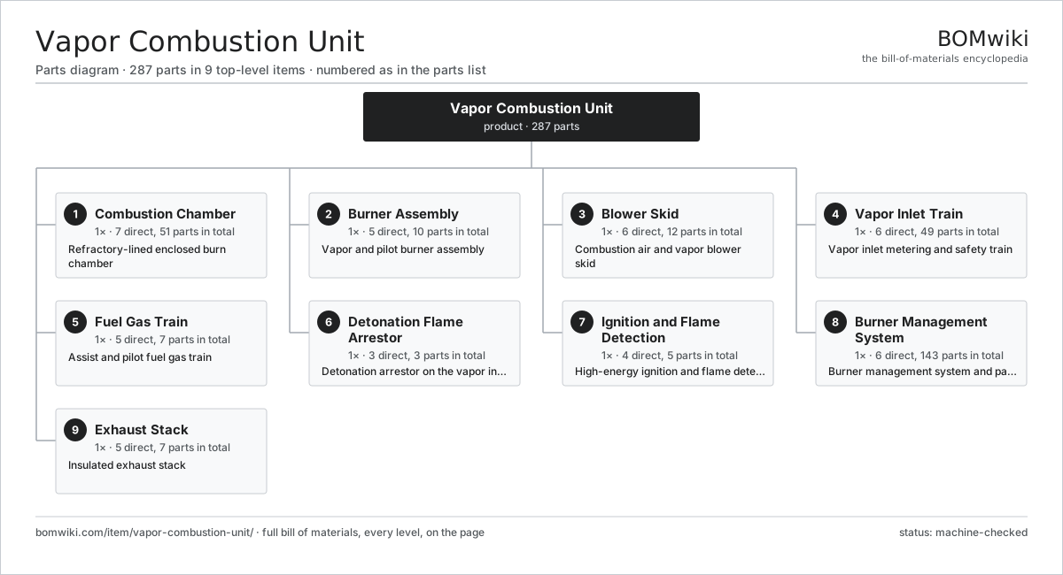
| # | Part | Qty | What it does |
|---|---|---|---|
| 1 | Combustion Chamber 7 parts | 1× | Refractory-lined enclosed burn chamber |
| 2 | Burner Assembly 5 parts | 1× | Vapor and pilot burner assembly |
| 3 | Blower Skid 6 parts | 1× | Combustion air and vapor blower skid |
| 4 | Vapor Inlet Train 6 parts | 1× | Vapor inlet metering and safety train |
| 5 | Fuel Gas Train 5 parts | 1× | Assist and pilot fuel gas train |
| 6 | Detonation Flame Arrestor 3 parts | 1× | Detonation arrestor on the vapor inlet |
| 7 | Ignition and Flame Detection 4 parts | 1× | High-energy ignition and flame detection |
| 8 | Burner Management System 6 parts | 1× | Burner management system and panel |
| 9 | Exhaust Stack 5 parts | 1× | Insulated exhaust stack |
3D model
No 3D model yet. Have a CAD file of this? Add a 3D model. STL renders right on this page; STEP, FreeCAD, and OpenSCAD sources are welcome too (openly licensed, like all 3D models on BOMwiki).
Build & assembly graph
expand / collapse · shared sub-assemblies converge · links to related products · est. labourTap an assembly to expand/collapse · tap a part to open it · use “Open page” for any node · drag to pan, scroll to zoom.
Bill of materials for Vapor Combustion Unit
9 top-level lines · 78 rows shown · 287 parts total · indented to 3 levels| # | Item / sub-assembly | Part no. | Qty/assy | Ext. qty | Parts | Type |
|---|---|---|---|---|---|---|
| 1 | Combustion Chamber 7 parts | vapor-combustion-unit-combustion-chamber | 1× | 1 | 51 | assembly |
| 1.1 | Chamber Shell | vapor-combustion-unit-chamber-shell | 1× | 1 | · | part |
| 1.2 | Refractory Lining 3 parts | vapor-combustion-unit-refractory | 1× | 1 | 42 | assembly |
| 1.2.1 | Ceramic-Fiber Blanket | vapor-combustion-unit-refractory-blanket | 1× | 1 | · | part |
| 1.2.2 | Refractory Anchor | vapor-combustion-unit-refractory-anchor | 40× | 40 | · | part |
| 1.2.3 | Insulation Board | vapor-combustion-unit-refractory-board | 1× | 1 | · | part |
| 1.3 | Burner Tile | vapor-combustion-unit-burner-tile | 1× | 1 | · | part |
| 1.4 | Chamber Thermocouple | vapor-combustion-unit-thermocouple | 3× | 3 | · | part |
| 1.5 | Sight Port | vapor-combustion-unit-sight-port | 1× | 1 | · | part |
| 1.6 | Air Damper | vapor-combustion-unit-air-damper | 1× | 1 | · | part |
| 1.7 | Fastener Set | fastener-set | 2× | 2 | · | part |
| 2 | Burner Assembly 5 parts | vapor-combustion-unit-burner | 1× | 1 | 10 | assembly |
| 2.1 | Vapor Nozzle Ring | vapor-combustion-unit-vapor-nozzle | 1× | 1 | · | part |
| 2.2 | Assist-Gas Nozzle | vapor-combustion-unit-assist-nozzle | 4× | 4 | · | part |
| 2.3 | Pilot Burner 3 parts | vapor-combustion-unit-pilot | 1× | 1 | 3 | assembly |
| 2.3.1 | Pilot Nozzle | vapor-combustion-unit-pilot-nozzle | 1× | 1 | · | part |
| 2.3.2 | Igniter Electrode | vapor-combustion-unit-pilot-rod | 1× | 1 | · | part |
| 2.3.3 | Pilot Mixer Tube | vapor-combustion-unit-pilot-tube | 1× | 1 | · | part |
| 2.4 | Burner Body | vapor-combustion-unit-burner-body | 1× | 1 | · | part |
| 2.5 | Mixing Plate | vapor-combustion-unit-mixing-plate | 1× | 1 | · | part |
| 3 | Blower Skid 6 parts | vapor-combustion-unit-blower-skid | 1× | 1 | 12 | assembly |
| 3.1 | Combustion Air Blower 4 parts | vapor-combustion-unit-air-blower | 1× | 1 | 5 | assembly |
| 3.1.1 | Blower Housing | vapor-combustion-unit-blower-housing | 1× | 1 | · | part |
| 3.1.2 | Blower Impeller | vapor-combustion-unit-blower-impeller | 1× | 1 | · | part |
| 3.1.3 | Ball Bearing | ball-bearing | 2× | 2 | · | part |
| 3.1.4 | Oil Seal | oil-seal | 1× | 1 | · | part |
| 3.2 | Vapor Booster Blower | vapor-combustion-unit-vapor-blower | 1× | 1 | · | part |
| 3.3 | Blower Motor | vapor-combustion-unit-blower-motor | 2× | 2 | · | part |
| 3.4 | Air Flow VFD | vapor-combustion-unit-vfd | 1× | 1 | · | part |
| 3.5 | Blower Skid Base | vapor-combustion-unit-blower-base | 1× | 1 | · | part |
| 3.6 | Drive Belt | drive-belt | 2× | 2 | · | part |
| 4 | Vapor Inlet Train 6 parts | vapor-combustion-unit-vapor-train | 1× | 1 | 49 | assembly |
| 4.1 | Vapor Control Valve | vapor-combustion-unit-vapor-valve | 1× | 1 | · | part |
| 4.2 | Vapor Shutoff Valve | vapor-combustion-unit-vapor-shutoff | 2× | 2 | · | part |
| 4.3 | Hydrocarbon Analyzer 4 parts | vapor-combustion-unit-lel-analyzer | 1× | 1 | 43 | assembly |
| 4.3.1 | Bare PCB | pcb-bare | 1× | 1 | · | part |
| 4.3.2 | Microcontroller | mcu | 1× | 1 | · | part |
| 4.3.3 | IR Sensing Cell | vapor-combustion-unit-ir-cell | 1× | 1 | · | part |
| 4.3.4 | SMD Passive (R/C/L) | smd-passives | 40× | 40 | · | part |
| 4.4 | Knockout Drum | vapor-combustion-unit-vapor-knockout | 1× | 1 | · | part |
| 4.5 | Vapor Pressure Transmitter | vapor-combustion-unit-vapor-pressure-xmtr | 1× | 1 | · | part |
| 4.6 | Pressure Sensor | pressure-sensor | 1× | 1 | · | part |
| 5 | Fuel Gas Train 5 parts | vapor-combustion-unit-fuel-gas-train | 1× | 1 | 7 | assembly |
| 5.1 | Gas Regulator | vapor-combustion-unit-gas-regulator | 1× | 1 | · | part |
| 5.2 | Safety Shutoff Valve | vapor-combustion-unit-gas-shutoff | 2× | 2 | · | part |
| 5.3 | Vent Valve | vapor-combustion-unit-gas-vent-valve | 1× | 1 | · | part |
| 5.4 | Gas Filter | vapor-combustion-unit-gas-filter | 1× | 1 | · | part |
| 5.5 | Gas Pressure Switch | vapor-combustion-unit-gas-pressure-switch | 2× | 2 | · | part |
| 6 | Detonation Flame Arrestor 3 parts | vapor-combustion-unit-flame-arrestor | 1× | 1 | 3 | assembly |
| 6.1 | Arrestor Element | vapor-combustion-unit-arrestor-element | 1× | 1 | · | part |
| 6.2 | Arrestor Housing | vapor-combustion-unit-arrestor-housing | 1× | 1 | · | part |
| 6.3 | Arrestor Temperature Sensor | vapor-combustion-unit-arrestor-temp-sensor | 1× | 1 | · | part |
| 7 | Ignition and Flame Detection 4 parts | vapor-combustion-unit-ignition-system | 1× | 1 | 5 | assembly |
| 7.1 | Ignition Exciter | vapor-combustion-unit-ignition-transformer | 1× | 1 | · | part |
| 7.2 | Flame Scanner | vapor-combustion-unit-flame-scanner | 2× | 2 | · | part |
| 7.3 | Ignition Cable | vapor-combustion-unit-ignition-cable | 1× | 1 | · | part |
| 7.4 | Flame Rod | vapor-combustion-unit-flame-rod | 1× | 1 | · | part |
| 8 | Burner Management System 6 parts | vapor-combustion-unit-control-system | 1× | 1 | 143 | assembly |
| 8.1 | BMS Controller 4 parts | vapor-combustion-unit-bms-controller | 1× | 1 | 124 | assembly |
| 8.1.1 | Bare PCB | pcb-bare | 1× | 1 | · | part |
| 8.1.2 | Microcontroller | mcu | 2× | 2 | · | part |
| 8.1.3 | SMD Passive (R/C/L) | smd-passives | 120× | 120 | · | part |
| 8.1.4 | Power Supply | power-supply | 1× | 1 | · | part |
| 8.2 | Control Panel 4 parts | vapor-combustion-unit-control-panel | 1× | 1 | 9 | assembly |
| 8.2.1 | I/O Module | vapor-combustion-unit-io-module | 3× | 3 | · | part |
| 8.2.2 | Purge Unit | vapor-combustion-unit-purge-unit | 1× | 1 | · | part |
| 8.2.3 | Power Supply | power-supply | 1× | 1 | · | part |
| 8.2.4 | Relay | relay | 4× | 4 | · | part |
| 8.3 | Operator Touchscreen | vapor-combustion-unit-hmi | 1× | 1 | · | part |
| 8.4 | Emergency Stop Button | vapor-combustion-unit-esd-button | 2× | 2 | · | part |
| 8.5 | Relay | relay | 6× | 6 | · | part |
| 8.6 | Wire Bundle | wire-bundle | 1× | 1 | · | part |
| 9 | Exhaust Stack 5 parts | vapor-combustion-unit-stack | 1× | 1 | 7 | assembly |
| 9.1 | Stack Shell | vapor-combustion-unit-stack-shell | 1× | 1 | · | part |
| 9.2 | Sampling Port | vapor-combustion-unit-stack-sample-port | 1× | 1 | · | part |
| 9.3 | Stack Oxygen Probe | vapor-combustion-unit-stack-o2-probe | 1× | 1 | · | part |
| 9.4 | Rain Cap | vapor-combustion-unit-stack-rain-cap | 1× | 1 | · | part |
| 9.5 | Guy Wire Set | vapor-combustion-unit-stack-guy-wires | 3× | 3 | · | part |
Related products
same domain, ranked by shared parts Drilling Mud Degasser
154 parts · shares 5 with this page
PCP Artificial Lift System
781 parts · shares 4 with this page
Drilling Mud Degasser
154 parts · shares 5 with this page
PCP Artificial Lift System
781 parts · shares 4 with this page
 Oil Pumpjack
141 parts · shares 3 with this page
Oil Pumpjack
141 parts · shares 3 with this page
 Reciprocating Gas Compressor Package
187 parts · shares 3 with this page
CO2 Injection Pump
463 parts · shares 4 with this page
Reciprocating Gas Compressor Package
187 parts · shares 3 with this page
CO2 Injection Pump
463 parts · shares 4 with this page
 Iron Roughneck
104 parts · shares 4 with this page
Iron Roughneck
104 parts · shares 4 with this page
Sourcing: possible vendors
Browse the supplier directory → Prices, MOQ, and lead times are algorithmic estimates, not quotes, and not claims about these companies. Company mappings are curated by keyword; est. price band $10k–$50M. How estimates work| Vendor | HQ | Specialty | MOQ | Lead time |
|---|---|---|---|---|
|
🇺🇸SLB
slb.com ↗
|
Houston, US | Oilfield services & equipment | made to order | 24–48 wks |
| halliburton.com ↗ | Houston, US | Oilfield services | made to order | 24–48 wks |
| bakerhughes.com ↗ | Houston, US | Energy technology | made to order | 24–48 wks |
|
🇺🇸NOV
nov.com ↗
|
Houston, US | Drilling equipment | made to order | 24–48 wks |
| technipfmc.com ↗ | London, GB | Subsea & surface systems | made to order | 24–48 wks |
941-word article