Hydrocracker Reactor
ProductOverview
A hydrocracker reactor converts heavy oil fractions into clean transportation fuels by cracking large molecules in the presence of high-pressure hydrogen. Where the FCC unit cracks thermally and catalytically without much hydrogen, the hydrocracker floods the reaction with hydrogen at very high pressure, which saturates the products, removes sulfur and nitrogen, and yields high-quality diesel, jet fuel, and naphtha. The trade-off is severe operating conditions: pressures up to 3,000 psi and temperatures over 800 F, with hydrogen, which together demand one of the heaviest and most carefully engineered vessels in any refinery.
The reactor is a tall forged vessel holding stacked beds of catalyst. Preheated feed mixed with hydrogen enters the top, flows down through the beds, and the cracked product leaves the bottom. The reactions release a lot of heat, so cold hydrogen is injected between beds to hold the temperature in a safe band. The Reactor Vessel is the pressure boundary, the Catalyst Bed System holds the reaction, and the Quench System keeps it under control.
How it works
Feed and hydrogen enter through the Feed Distribution System system. The Inlet Diffuser breaks the incoming jet and the Distributor Tray with its many Distributor Cap caps spreads the two-phase mixture evenly so every part of the top bed is wetted. Uneven distribution would leave dry zones that overheat and coke, so distributor design is critical. The fluid flows down through the first Catalyst Charge bed sitting on a Support Grid and screen, topped by an Inert Ball Layer that traps scale and spreads flow.
In the bed, hydrotreating catalyst first removes sulfur and nitrogen and saturates aromatics, then cracking catalyst breaks the heavy molecules into lighter ones. Both reactions give off heat, raising the temperature as the fluid descends. Before the next bed, the Quench System steps in: a Quench Distributor injects cold recycle hydrogen, a Quench Mixing Chamber blends it with the hot effluent to a uniform temperature, and a Redistribution Tray re-spreads the flow for the bed below. This resets the temperature at each bed inlet and is the main lever for controlling the runaway-prone reaction. Product collects at the bottom on the Outlet Collector and leaves through the bottom nozzle.
Metallurgy and hydrogen attack
The vessel operates where hydrogen, at high pressure and temperature, attacks ordinary steel. Atomic hydrogen diffuses into the metal and reacts with carbides, forming methane that builds internal pressure and cracks the steel, a mechanism called high-temperature hydrogen attack governed by the Nelson curves in API 941. To resist it, the Forged Shell Ring sections are made from 2.25Cr-1Mo-V steel, a vanadium-modified chromium-molybdenum alloy with both the strength for the thickness and the resistance to hydrogen attack. The walls are six to twelve inches thick and built from seamless forgings rather than rolled plate to avoid weld seams in the most stressed regions. The wetted inside carries a stainless Weld Overlay Cladding of 347 to resist sulfidation and to keep hydrogen-charged base metal away from the process. Nozzles are forged and overlaid, with Thermal Sleeve sleeves protecting welds from thermal shock at feed and quench points.
Recycle gas loop
The reactor consumes hydrogen but circulates far more than it consumes, because a large hydrogen excess keeps partial pressure high and suppresses coking. The Recycle Gas Loop handles this. The Recycle Gas Compressor, a centrifugal machine with dry gas seals, circulates the hydrogen-rich gas through the reactor. Hydrogen sulfide formed by desulfurization is washed out in the Amine Scrubber to keep purity up, and the Makeup Hydrogen Compressor tops up the hydrogen actually consumed by the reactions. The Hydrogen Analyzer tracks purity, since falling hydrogen partial pressure both slows the reaction and raises the coking and temperature-excursion risk.
Safety and control
The defining hazard is a temperature excursion. If the reaction runs away, the exotherm can outpace the quench, and within minutes the bed can reach temperatures that damage catalyst, internals, and even the vessel. The Instrument Package therefore carries a dense grid of Bed Thermocouple points mapping temperature radially and axially through every bed, plus Skin Thermocouple points on the wall. A safety instrumented system in the Control Panel triggers emergency depressuring through the Depressuring Valve valves in the Piping Package, dumping reactor pressure to flare to quench the reaction by removing hydrogen partial pressure. Operators manage normal temperature through the Quench Control Valve valves, raising catalyst inlet temperatures slowly over a run to compensate for catalyst aging.
Operation and variants
Hydrocrackers are configured as single-stage, single-stage with recycle, or two-stage units depending on the conversion and product slate wanted. Higher conversion needs more catalyst volume, more beds, and tighter temperature control. The Catalyst Charge is loaded through the Top Closure and dumped through the Bottom Closure at turnaround, when spent catalyst is replaced and the overlay and internals are inspected. A reactor runs one to several years between turnarounds, with run length set by catalyst deactivation and by the metallurgical inspection intervals that high-pressure hydrogen service demands. Reliable feed distribution, quench control, and metallurgy together set both the safety and the profitability of the unit.
Hydrocracker Reactor parts and their functions
9 top-level parts · 314 parts in total · full bill of materials below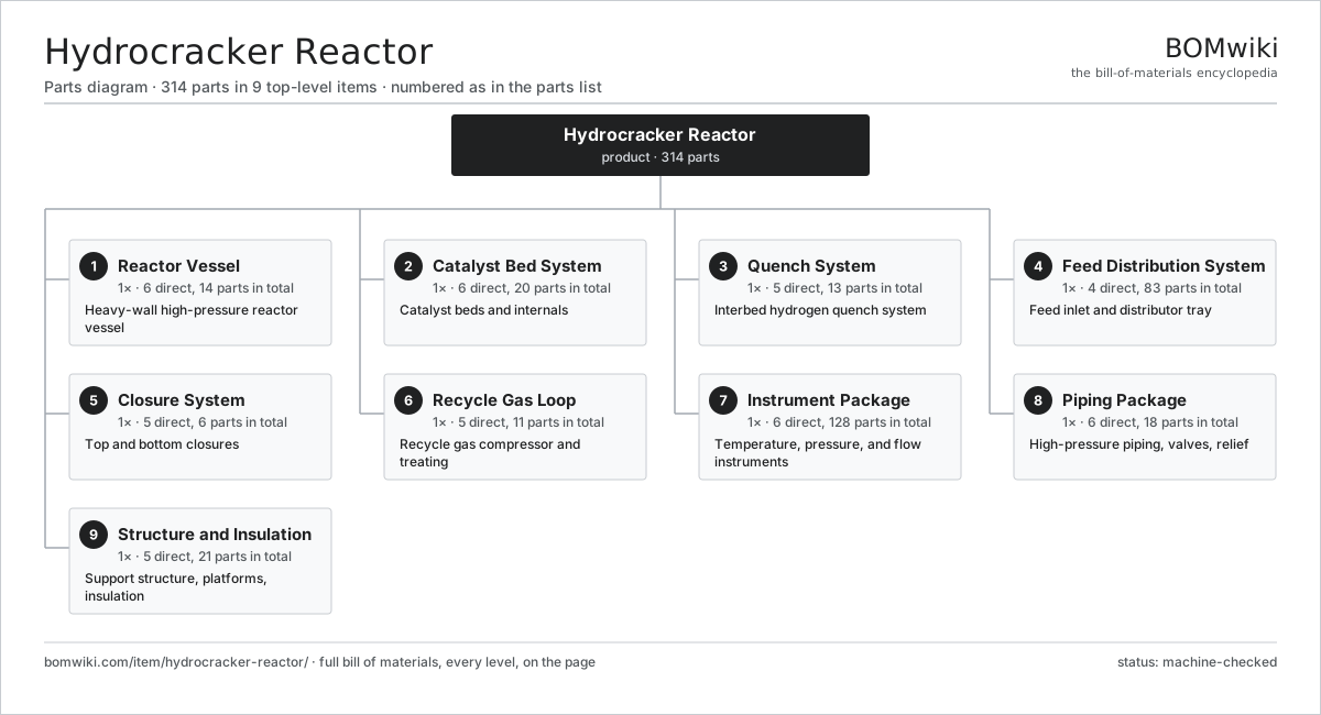
| # | Part | Qty | What it does |
|---|---|---|---|
| 1 | Reactor Vessel 6 parts | 1× | Heavy-wall high-pressure reactor vessel |
| 2 | Catalyst Bed System 6 parts | 1× | Catalyst beds and internals |
| 3 | Quench System 5 parts | 1× | Interbed hydrogen quench system |
| 4 | Feed Distribution System 4 parts | 1× | Feed inlet and distributor tray |
| 5 | Closure System 5 parts | 1× | Top and bottom closures |
| 6 | Recycle Gas Loop 5 parts | 1× | Recycle gas compressor and treating |
| 7 | Instrument Package 6 parts | 1× | Temperature, pressure, and flow instruments |
| 8 | Piping Package 6 parts | 1× | High-pressure piping, valves, relief |
| 9 | Structure and Insulation 5 parts | 1× | Support structure, platforms, insulation |
3D model
No 3D model yet. Have a CAD file of this? Add a 3D model. STL renders right on this page; STEP, FreeCAD, and OpenSCAD sources are welcome too (openly licensed, like all 3D models on BOMwiki).
Build & assembly graph
expand / collapse · shared sub-assemblies converge · links to related products · est. labourTap an assembly to expand/collapse · tap a part to open it · use “Open page” for any node · drag to pan, scroll to zoom.
Bill of materials for Hydrocracker Reactor
9 top-level lines · 68 rows shown · 314 parts total · indented to 3 levels| # | Item / sub-assembly | Part no. | Qty/assy | Ext. qty | Parts | Type |
|---|---|---|---|---|---|---|
| 1 | Reactor Vessel 6 parts | hcr-reactor-vessel | 1× | 1 | 14 | assembly |
| 1.1 | Forged Shell Ring | hcr-forged-shell-ring | 5× | 5 | · | part |
| 1.2 | Vessel Head | hcr-vessel-head | 2× | 2 | · | part |
| 1.3 | Weld Overlay Cladding | hcr-weld-overlay | 1× | 1 | · | part |
| 1.4 | Nozzle Forging | hcr-nozzle-forging | 1× | 1 | · | part |
| 1.5 | Support Skirt Forging | hcr-skirt-support | 1× | 1 | · | part |
| 1.6 | Thermal Sleeve | hcr-thermal-sleeve | 4× | 4 | · | part |
| 2 | Catalyst Bed System 6 parts | hcr-catalyst-bed-system | 1× | 1 | 20 | assembly |
| 2.1 | Catalyst Charge | hcr-catalyst-charge | 4× | 4 | · | part |
| 2.2 | Support Grid | hcr-support-grid | 4× | 4 | · | part |
| 2.3 | Support Screen | hcr-support-screen | 4× | 4 | · | part |
| 2.4 | Inert Ball Layer | hcr-inert-ball-layer | 4× | 4 | · | part |
| 2.5 | Collector Tray | hcr-collector-tray | 3× | 3 | · | part |
| 2.6 | Outlet Collector | hcr-outlet-collector | 1× | 1 | · | part |
| 3 | Quench System 5 parts | hcr-quench-system | 1× | 1 | 13 | assembly |
| 3.1 | Quench Distributor | hcr-quench-distributor | 3× | 3 | · | part |
| 3.2 | Quench Mixing Chamber | hcr-quench-mixing-chamber | 3× | 3 | · | part |
| 3.3 | Redistribution Tray | hcr-redistribution-tray | 3× | 3 | · | part |
| 3.4 | Quench Control Valve | hcr-quench-control-valve | 3× | 3 | · | part |
| 3.5 | Quench Header | hcr-quench-header | 1× | 1 | · | part |
| 4 | Feed Distribution System 4 parts | hcr-feed-distribution | 1× | 1 | 83 | assembly |
| 4.1 | Inlet Diffuser | hcr-inlet-diffuser | 1× | 1 | · | part |
| 4.2 | Distributor Tray | hcr-distributor-tray | 1× | 1 | · | part |
| 4.3 | Distributor Cap | hcr-distributor-cap | 80× | 80 | · | part |
| 4.4 | Feed Nozzle | hcr-feed-nozzle | 1× | 1 | · | part |
| 5 | Closure System 5 parts | hcr-closure-system | 1× | 1 | 6 | assembly |
| 5.1 | Top Closure | hcr-top-closure | 1× | 1 | · | part |
| 5.2 | Bottom Closure | hcr-bottom-closure | 1× | 1 | · | part |
| 5.3 | Closure Studs | hcr-closure-studs | 1× | 1 | · | part |
| 5.4 | Closure Gasket | hcr-closure-gasket | 2× | 2 | · | part |
| 5.5 | Catalyst Dump Nozzle | hcr-catalyst-dump-nozzle | 1× | 1 | · | part |
| 6 | Recycle Gas Loop 5 parts | hcr-recycle-gas-loop | 1× | 1 | 11 | assembly |
| 6.1 | Recycle Gas Compressor 5 parts | hcr-recycle-compressor | 1× | 1 | 7 | assembly |
| 6.1.1 | Compressor Rotor | hcr-compressor-rotor | 1× | 1 | · | part |
| 6.1.2 | Compressor Casing | hcr-compressor-casing | 1× | 1 | · | part |
| 6.1.3 | Dry Gas Seal | hcr-dry-gas-seal | 2× | 2 | · | part |
| 6.1.4 | Ball Bearing | ball-bearing | 2× | 2 | · | part |
| 6.1.5 | Compressor Driver | hcr-compressor-driver | 1× | 1 | · | part |
| 6.2 | Amine Scrubber | hcr-amine-scrubber | 1× | 1 | · | part |
| 6.3 | Makeup Hydrogen Compressor | hcr-makeup-compressor | 1× | 1 | · | part |
| 6.4 | Recycle Cooler | hcr-recycle-cooler | 1× | 1 | · | part |
| 6.5 | Knockout Drum | hcr-knockout-drum | 1× | 1 | · | part |
| 7 | Instrument Package 6 parts | hcr-instrument-package | 1× | 1 | 128 | assembly |
| 7.1 | Bed Thermocouple | hcr-bed-thermocouple | 40× | 40 | · | part |
| 7.2 | Skin Thermocouple | hcr-skin-thermocouple | 12× | 12 | · | part |
| 7.3 | Pressure Sensor | pressure-sensor | 6× | 6 | · | part |
| 7.4 | Flow Meter | hcr-flow-meter | 4× | 4 | · | part |
| 7.5 | Hydrogen Analyzer | hcr-hydrogen-analyzer | 1× | 1 | · | part |
| 7.6 | Control Panel 6 parts | hcr-control-panel | 1× | 1 | 65 | assembly |
| 7.6.1 | Bare PCB | pcb-bare | 3× | 3 | · | part |
| 7.6.2 | Microcontroller | mcu | 3× | 3 | · | part |
| 7.6.3 | Relay | relay | 16× | 16 | · | part |
| 7.6.4 | Power Supply | power-supply | 2× | 2 | · | part |
| 7.6.5 | Connector | connector | 40× | 40 | · | part |
| 7.6.6 | Wire Bundle | wire-bundle | 1× | 1 | · | part |
| 8 | Piping Package 6 parts | hcr-piping-package | 1× | 1 | 18 | assembly |
| 8.1 | High-Pressure Piping | hcr-hp-piping | 1× | 1 | · | part |
| 8.2 | Isolation Valve | hcr-isolation-valve | 8× | 8 | · | part |
| 8.3 | Depressuring Valve | hcr-depressuring-valve | 2× | 2 | · | part |
| 8.4 | Relief Valve | hcr-relief-valve | 2× | 2 | · | part |
| 8.5 | Check Valve | hcr-check-valve | 4× | 4 | · | part |
| 8.6 | Fastener Set | fastener-set | 1× | 1 | · | part |
| 9 | Structure and Insulation 5 parts | hcr-structure | 1× | 1 | 21 | assembly |
| 9.1 | Structure Steel | hcr-structure-steel | 1× | 1 | · | part |
| 9.2 | Access Platform | hcr-platform | 6× | 6 | · | part |
| 9.3 | Thermal Insulation | hcr-insulation | 1× | 1 | · | part |
| 9.4 | Sheet Metal Panel | sheet-panel | 12× | 12 | · | part |
| 9.5 | Fastener Set | fastener-set | 1× | 1 | · | part |
Related products
same domain, ranked by shared parts Amine Gas Sweetening Unit
3,543 parts · shares 3 with this page
CO2 Injection Pump
463 parts · shares 3 with this page
Amine Gas Sweetening Unit
3,543 parts · shares 3 with this page
CO2 Injection Pump
463 parts · shares 3 with this page
 Condensate Stabilizer Column
2,234 parts · shares 3 with this page
Condensate Stabilizer Column
2,234 parts · shares 3 with this page
 Delayed Coker Drum
208 parts · shares 3 with this page
Delayed Coker Drum
208 parts · shares 3 with this page
 Drilling Mud Degasser
154 parts · shares 3 with this page
Drilling Mud Degasser
154 parts · shares 3 with this page
 Drilling Mud Mixing System
135 parts · shares 3 with this page
Drilling Mud Mixing System
135 parts · shares 3 with this page
Sourcing: possible vendors
Browse the supplier directory → Prices, MOQ, and lead times are algorithmic estimates, not quotes, and not claims about these companies. Company mappings are curated by keyword; est. price band $10k–$50M. How estimates work| Vendor | HQ | Specialty | MOQ | Lead time |
|---|---|---|---|---|
|
🇺🇸SLB
slb.com ↗
|
Houston, US | Oilfield services & equipment | made to order | 24–48 wks |
| halliburton.com ↗ | Houston, US | Oilfield services | made to order | 24–48 wks |
| bakerhughes.com ↗ | Houston, US | Energy technology | made to order | 24–48 wks |
|
🇺🇸NOV
nov.com ↗
|
Houston, US | Drilling equipment | made to order | 24–48 wks |
| technipfmc.com ↗ | London, GB | Subsea & surface systems | made to order | 24–48 wks |
895-word article