Pipeline Block Valve Station
ProductOverview
A pipeline block valve station is a point along a pipeline where a single large valve can close to cut the line into sections. When a leak, rupture or planned repair happens, closing the valves on either side of the affected stretch isolates it, which limits how much product escapes and lets a crew work safely. These stations sit at intervals set by regulation along the whole length of a transmission pipeline, so any section can be shut in without draining the entire line.
The station is more than the valve. It includes the means to close that valve even when the grid is down, to equalize and vent the isolated section, and to detect a rupture and act on its own. Everything is built to operate at a remote, unmanned site and to be commanded from a control center hundreds of kilometers away.
Main block valve
The Main Block Valve is the centerpiece, almost always a trunnion-mounted ball valve. Its welded Valve Body is full-bore so cleaning and inspection pigs pass straight through, and inside, a Valve Ball rotates a quarter turn to seal or open the line. The ball is carried on Trunnion bearings so that line pressure does not jam it against the seats, which keeps the operating torque low even on a large high-pressure valve. Spring-energized Seat Ring seats seal against the ball at any pressure, and the Valve Stem carries the actuator torque down to the ball. For emergencies, Sealant Fitting fittings let a crew inject sealant to restore a leaking seat without taking the valve out of service.
Actuator
A block valve has to close during the worst moment, often a rupture that has knocked out power, so the Actuator System is designed to need no outside electricity. The Gas-Over-Oil Actuator is a gas-over-oil unit: stored pipeline gas pushes on oil, and the oil drives the Actuator Piston in the Actuator Cylinder, whose travel is turned into a quarter-turn by a Scotch Yoke. The energy comes from a Gas Bottle of stored gas acting on the Hydraulic Reservoir of oil, so the valve can stroke even with everything else dead. A Hand Pump gives an operator a manual fallback, Limit Switch sensors confirm the valve reached its end position, and a set of Control Valve pilots routes the oil and gas.
Bypass and blowdown
Two support systems make the valve safe to operate. The Bypass System is a small loop with Bypass Valve valves around the main valve. Before reopening a valve that has the full line pressure on one side and an empty section on the other, the bypass equalizes the pressure across it, so the main valve does not slam open against a huge differential. Differential pressure sensors confirm when the two sides match.
The Blowdown System empties an isolated section so a crew can cut into it. Blowdown Valve valves release the trapped gas up a Vent Stack, with a Vent Silencer cutting the noise of the high-rate vent and a Flame Arrestor stopping any flame from traveling back down the stack. Venting to atmosphere has to happen high and away from the ground, which is why the stack is tall.
Control and detection
The Control System gives the station three ways to close. An operator can command it locally, the control center can command it through the Remote Terminal Unit over a SCADA link served by the SCADA Radio, or the station can decide for itself: a Line-Break Controller watches the line pressure through dedicated transmitters and, if the pressure falls at a rate that only a rupture produces, closes the valve automatically. That automatic line-break function is the reason these stations limit the damage from a major failure, because they act in seconds without waiting for a human.
Power, civil works and spacing
Because the site is remote, the Power System is self-sufficient. A Solar Panel array charges a Battery Bank through a charge controller, and where sunlight is unreliable a gas-fired Thermoelectric Generator backs it up, so the controls never lose power. The Civil Works tie it all to the ground: a reinforced Valve Foundation carries the valve and actuator, a Equipment Shelter keeps the controls dry, a Security Fence secures the site, and a Grounding Grid protects against lightning and faults.
How far apart these stations sit is set by the population around the pipeline. Regulations tighten the spacing in built-up areas and relax it in open country, so a line through a city has block valves much closer together than the same line crossing empty land. Liquid pipelines and gas pipelines both use the concept, with the valve, actuator and detection sized to the line size and the product it carries.
Pipeline Block Valve Station parts and their functions
7 top-level parts · 62 parts in total · full bill of materials below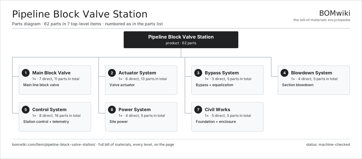
| # | Part | Qty | What it does |
|---|---|---|---|
| 1 | Main Block Valve 7 parts | 1× | Main line block valve |
| 2 | Actuator System 6 parts | 1× | Valve actuator |
| 3 | Bypass System 3 parts | 1× | Bypass + equalization |
| 4 | Blowdown System 4 parts | 1× | Section blowdown |
| 5 | Control System 8 parts | 1× | Station control + telemetry |
| 6 | Power System 4 parts | 1× | Site power |
| 7 | Civil Works 5 parts | 1× | Foundation + enclosure |
3D model
No 3D model yet. Have a CAD file of this? Add a 3D model. STL renders right on this page; STEP, FreeCAD, and OpenSCAD sources are welcome too (openly licensed, like all 3D models on BOMwiki).
Build & assembly graph
expand / collapse · shared sub-assemblies converge · links to related products · est. labourTap an assembly to expand/collapse · tap a part to open it · use “Open page” for any node · drag to pan, scroll to zoom.
Bill of materials for Pipeline Block Valve Station
7 top-level lines · 48 rows shown · 62 parts total · indented to 3 levels| # | Item / sub-assembly | Part no. | Qty/assy | Ext. qty | Parts | Type |
|---|---|---|---|---|---|---|
| 1 | Main Block Valve 7 parts | pbv-main-valve | 1× | 1 | 11 | assembly |
| 1.1 | Valve Body | pbv-valve-body | 1× | 1 | · | part |
| 1.2 | Valve Ball | pbv-ball | 1× | 1 | · | part |
| 1.3 | Seat Ring | pbv-seat-ring | 2× | 2 | · | part |
| 1.4 | Valve Stem | pbv-stem | 1× | 1 | · | part |
| 1.5 | Trunnion | pbv-trunnion | 2× | 2 | · | part |
| 1.6 | O-Ring Set | oring-set | 2× | 2 | · | part |
| 1.7 | Sealant Fitting | pbv-sealant-injection | 2× | 2 | · | part |
| 2 | Actuator System 6 parts | pbv-actuator-system | 1× | 1 | 13 | assembly |
| 2.1 | Gas-Over-Oil Actuator 4 parts | pbv-gas-actuator | 1× | 1 | 4 | assembly |
| 2.1.1 | Actuator Cylinder | pbv-actuator-cylinder | 1× | 1 | · | part |
| 2.1.2 | Actuator Piston | pbv-actuator-piston | 1× | 1 | · | part |
| 2.1.3 | Scotch Yoke | pbv-scotch-yoke | 1× | 1 | · | part |
| 2.1.4 | O-Ring Set | oring-set | 1× | 1 | · | part |
| 2.2 | Hydraulic Reservoir | pbv-hydraulic-tank | 1× | 1 | · | part |
| 2.3 | Gas Bottle | pbv-gas-tank | 1× | 1 | · | part |
| 2.4 | Hand Pump | pbv-hand-pump | 1× | 1 | · | part |
| 2.5 | Limit Switch | pbv-limit-switch | 2× | 2 | · | part |
| 2.6 | Control Valve | pbv-actuator-valve | 4× | 4 | · | part |
| 3 | Bypass System 3 parts | pbv-bypass-system | 1× | 1 | 5 | assembly |
| 3.1 | Bypass Valve | pbv-bypass-valve | 2× | 2 | · | part |
| 3.2 | Bypass Piping | pbv-bypass-piping | 1× | 1 | · | part |
| 3.3 | Pressure Sensor | pressure-sensor | 2× | 2 | · | part |
| 4 | Blowdown System 4 parts | pbv-blowdown-system | 1× | 1 | 5 | assembly |
| 4.1 | Blowdown Valve | pbv-blowdown-valve | 2× | 2 | · | part |
| 4.2 | Vent Stack | pbv-vent-stack | 1× | 1 | · | part |
| 4.3 | Vent Silencer | pbv-silencer | 1× | 1 | · | part |
| 4.4 | Flame Arrestor | pbv-flame-arrestor | 1× | 1 | · | part |
| 5 | Control System 8 parts | pbv-control-system | 1× | 1 | 18 | assembly |
| 5.1 | Remote Terminal Unit | pbv-rtu | 1× | 1 | · | part |
| 5.2 | Line-Break Controller | pbv-line-break-controller | 1× | 1 | · | part |
| 5.3 | Pressure Sensor | pressure-sensor | 4× | 4 | · | part |
| 5.4 | SCADA Radio | pbv-radio | 1× | 1 | · | part |
| 5.5 | Bare PCB | pcb-bare | 2× | 2 | · | part |
| 5.6 | Microcontroller | mcu | 2× | 2 | · | part |
| 5.7 | Relay | relay | 6× | 6 | · | part |
| 5.8 | Wire Bundle | wire-bundle | 1× | 1 | · | part |
| 6 | Power System 4 parts | pbv-power-system | 1× | 1 | 5 | assembly |
| 6.1 | Solar Panel | pbv-solar-panel | 2× | 2 | · | part |
| 6.2 | Battery Bank | pbv-battery-bank | 1× | 1 | · | part |
| 6.3 | Power Supply | power-supply | 1× | 1 | · | part |
| 6.4 | Thermoelectric Generator | pbv-thermoelectric-gen | 1× | 1 | · | part |
| 7 | Civil Works 5 parts | pbv-civil-works | 1× | 1 | 5 | assembly |
| 7.1 | Valve Foundation | pbv-valve-foundation | 1× | 1 | · | part |
| 7.2 | Equipment Shelter | pbv-equipment-shelter | 1× | 1 | · | part |
| 7.3 | Security Fence | pbv-security-fence | 1× | 1 | · | part |
| 7.4 | Grounding Grid | pbv-grounding-grid | 1× | 1 | · | part |
| 7.5 | Fastener Set | fastener-set | 1× | 1 | · | part |
Related products
same domain, ranked by shared parts Amine Gas Sweetening Unit
3,543 parts · shares 1 with this page
Amine Gas Sweetening Unit
3,543 parts · shares 1 with this page
 Centrifugal Gas Compressor
137 parts · shares 1 with this page
CO2 Injection Pump
463 parts · shares 1 with this page
Centrifugal Gas Compressor
137 parts · shares 1 with this page
CO2 Injection Pump
463 parts · shares 1 with this page
 Condensate Stabilizer Column
2,234 parts · shares 1 with this page
Condensate Stabilizer Column
2,234 parts · shares 1 with this page
 Delayed Coker Drum
208 parts · shares 1 with this page
Delayed Coker Drum
208 parts · shares 1 with this page
 Drilling Mud Degasser
154 parts · shares 1 with this page
Drilling Mud Degasser
154 parts · shares 1 with this page
Sourcing: possible vendors
Browse the supplier directory → Prices, MOQ, and lead times are algorithmic estimates, not quotes, and not claims about these companies. Company mappings are curated by keyword; est. price band $10k–$50M. How estimates work| Vendor | HQ | Specialty | MOQ | Lead time |
|---|---|---|---|---|
|
🇺🇸SLB
slb.com ↗
|
Houston, US | Oilfield services & equipment | made to order | 24–48 wks |
| halliburton.com ↗ | Houston, US | Oilfield services | made to order | 24–48 wks |
| bakerhughes.com ↗ | Houston, US | Energy technology | made to order | 24–48 wks |
|
🇺🇸NOV
nov.com ↗
|
Houston, US | Drilling equipment | made to order | 24–48 wks |
| technipfmc.com ↗ | London, GB | Subsea & surface systems | made to order | 24–48 wks |
829-word article