Gas Pressure Regulating Station
ProductOverview
A gas pressure regulating and metering station, often called an M&R station or city gate, is the skid that sits between a high-pressure transmission pipeline and a lower-pressure distribution grid. Its job is to drop the gas to a controlled outlet pressure, hold that pressure steady as demand swings, protect the downstream network from overpressure, and measure the volume of gas delivered for custody transfer and billing. A typical station handles inlet pressures from 19 to 75 bar and delivers an outlet anywhere from 0.1 bar for a local low-pressure grid up to 19 bar for an industrial feeder.
The station is built as a packaged skid so it can be tested at the fabricator and dropped onto a prepared foundation on site. The Skid Frame and Piping carries the structural base, the inlet and outlet manifolds, and the weather paneling that turns the skid into a walk-in housing in cold climates. All of the active subsystems bolt onto that frame.
How it works
Gas enters through the Inlet Filter Separator, which spins out bulk liquids in a cyclone and then passes the stream through coalescing cartridges that capture fine mist and particulate down to around 0.3 micron. Clean gas matters because liquids and grit damage regulator seats and skew meter readings. A differential pressure gauge across the elements tells operators when the cartridges need changing.
Downstream of filtration the gas reaches the regulator section. The Pressure Regulator Run is built as a worker and monitor pair. The worker regulator does the day-to-day control, throttling its plug against the seat to hold the outlet at the set point as flow changes. The Worker Regulator is pilot-operated: a small pilot senses outlet pressure and loads the main diaphragm, which gives tight control across a wide flow range. Sitting in series with it, the Monitor Regulator stays wide open during normal operation and only begins to control if the worker fails open. That arrangement gives a second independent line of defense without interrupting flow. Stations are usually configured with two parallel runs, one duty and one standby, so a regulator can be isolated and serviced while gas keeps flowing.
Metering and volume correction
Measurement happens in the Metering Run. A flow conditioner flattens the velocity profile ahead of the primary meter, which on modern stations is an ultrasonic meter, though turbine meters remain common. The meter measures actual volume at flowing conditions. Because gas volume depends strongly on pressure and temperature, a Pressure Sensor and an RTD feed the Flow Computer Cabinet, which applies the AGA 8 compressibility equation and ISO 5167 corrections to report a standardized corrected volume. The flow computer logs hourly and daily totals, holds alarm limits, and passes data to the control system.
Safety and overpressure protection
Overpressure protection is layered. The first active layer is the Slam-Shut Safety Device, a spring-latched valve upstream of the regulators that trips fully closed within a fraction of a second if downstream pressure rises above or falls below its set points. It must be reset by hand, which forces an operator to investigate before gas flows again. Behind that sits the Relief System, with a small creep relief that bleeds off the slow pressure rise caused by a weeping regulator seat, plus a full-capacity relief valve that vents to a stack if pressure climbs faster than the creep relief can handle. EN 12186 and ASME B31.8 set the rules for how these layers are sized and combined.
Gas heating
When high-pressure gas expands across a regulator it cools sharply through the Joule-Thomson effect, roughly 0.5 °C for every bar of pressure drop. A drop of 50 bar can chill the gas by 25 °C, which can form hydrates or freeze valve internals. The Gas Preheater is an indirect water-bath heater that warms the gas before regulation so the outlet stays above the hydrate and dew-point range. A submerged fire tube heats a water bath, and the station gas flows through a coil in that bath. A Heating Element can serve as an electric backup where a burner is not practical.
Materials and construction
Pressure-containing parts are carbon steel forgings and castings to ASTM A105 and A106, with stainless steel trim on seats and stems for erosion resistance. Bodies and flanges are rated to ANSI Class 300 or 600 to match the inlet pressure. Sealing uses elastomer O-ring sets and reinforced diaphragms chosen for the gas composition and temperature band. The Insulation Joint electrically isolates the station from the cathodically protected pipeline.
Variants and applications
City-gate stations feed municipal grids and emphasize turndown and noise control, since they throttle from transmission pressure to a few bar in a populated area. Industrial M&R skids serve a single large customer such as a power plant or a glassworks, where custody metering accuracy drives the design. Pressure reduction stations inside a distribution network step from medium to low pressure without custody metering. District regulator stations are smaller variants that omit the heater where the pressure drop is modest. Across all of these the Control and Telemetry Cabinet provides telemetry so a control center can watch pressures, flows, and alarms across many sites at once.
Gas Pressure Regulating Station parts and their functions
9 top-level parts · 133 parts in total · full bill of materials below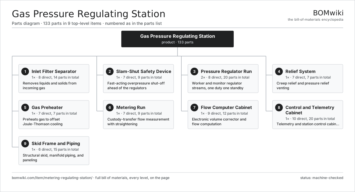
| # | Part | Qty | What it does |
|---|---|---|---|
| 1 | Inlet Filter Separator 8 parts | 1× | Removes liquids and solids from incoming gas |
| 2 | Slam-Shut Safety Device 7 parts | 1× | Fast-acting overpressure shut-off ahead of the regulators |
| 3 | Pressure Regulator Run 8 parts | 2× | Worker and monitor regulator streams, one duty one standby |
| 4 | Relief System 7 parts | 1× | Creep relief and pressure relief venting |
| 5 | Gas Preheater 7 parts | 1× | Preheats gas to offset Joule-Thomson cooling |
| 6 | Metering Run 7 parts | 1× | Custody-transfer flow measurement with straightening |
| 7 | Flow Computer Cabinet 9 parts | 1× | Electronic volume corrector and flow computation |
| 8 | Control and Telemetry Cabinet 10 parts | 1× | Telemetry and station control cabinet |
| 9 | Skid Frame and Piping 6 parts | 1× | Structural skid, manifold piping, and paneling |
3D model
No 3D model yet. Have a CAD file of this? Add a 3D model. STL renders right on this page; STEP, FreeCAD, and OpenSCAD sources are welcome too (openly licensed, like all 3D models on BOMwiki).
Build & assembly graph
expand / collapse · shared sub-assemblies converge · links to related products · est. labourTap an assembly to expand/collapse · tap a part to open it · use “Open page” for any node · drag to pan, scroll to zoom.
Bill of materials for Gas Pressure Regulating Station
9 top-level lines · 88 rows shown · 133 parts total · indented to 3 levels| # | Item / sub-assembly | Part no. | Qty/assy | Ext. qty | Parts | Type |
|---|---|---|---|---|---|---|
| 1 | Inlet Filter Separator 8 parts | metering-regulating-station-inlet-filter-separator | 1× | 1 | 14 | assembly |
| 1.1 | Filter Separator Vessel | metering-regulating-station-fs-vessel | 1× | 1 | · | part |
| 1.2 | Cyclone Inlet | metering-regulating-station-fs-cyclone | 1× | 1 | · | part |
| 1.3 | Coalescer Element | metering-regulating-station-fs-coalescer-element | 4× | 4 | · | part |
| 1.4 | Condensate Drain Valve | metering-regulating-station-fs-drain-valve | 2× | 2 | · | part |
| 1.5 | Differential Pressure Gauge | metering-regulating-station-fs-diff-gauge | 1× | 1 | · | part |
| 1.6 | Separator Isolation Valve | metering-regulating-station-fs-isolation-valve | 2× | 2 | · | part |
| 1.7 | O-Ring Set | oring-set | 2× | 2 | · | part |
| 1.8 | Fastener Set | fastener-set | 1× | 1 | · | part |
| 2 | Slam-Shut Safety Device 7 parts | metering-regulating-station-slam-shut-safety | 1× | 1 | 9 | assembly |
| 2.1 | Slam-Shut Valve Body | metering-regulating-station-ss-valve-body | 1× | 1 | · | part |
| 2.2 | Trip Mechanism | metering-regulating-station-ss-trip-mechanism | 1× | 1 | · | part |
| 2.3 | Sensing Line | metering-regulating-station-ss-sense-line | 2× | 2 | · | part |
| 2.4 | Coil Spring | coil-spring | 2× | 2 | · | part |
| 2.5 | Pressure Sensor | pressure-sensor | 1× | 1 | · | part |
| 2.6 | O-Ring Set | oring-set | 1× | 1 | · | part |
| 2.7 | Fastener Set | fastener-set | 1× | 1 | · | part |
| 3 | Pressure Regulator Run 8 parts | metering-regulating-station-regulator-run | 2× | 2 | 20 | assembly |
| 3.1 | Worker Regulator 5 parts | metering-regulating-station-rr-worker-regulator | 1× | 2 | 5 | assembly |
| 3.1.1 | Regulator Valve Body | metering-regulating-station-reg-body | 1× | 2 | · | part |
| 3.1.2 | Regulator Diaphragm | metering-regulating-station-reg-diaphragm | 1× | 2 | · | part |
| 3.1.3 | Regulator Seat | metering-regulating-station-reg-seat | 1× | 2 | · | part |
| 3.1.4 | Stem and Plug | metering-regulating-station-reg-stem-plug | 1× | 2 | · | part |
| 3.1.5 | Coil Spring | coil-spring | 1× | 2 | · | part |
| 3.2 | Monitor Regulator 5 parts | metering-regulating-station-rr-monitor-regulator | 1× | 2 | 5 | assembly |
| 3.2.1 | Regulator Valve Body | metering-regulating-station-reg-body | 1× | 2 | · | part |
| 3.2.2 | Regulator Diaphragm | metering-regulating-station-reg-diaphragm | 1× | 2 | · | part |
| 3.2.3 | Regulator Seat | metering-regulating-station-reg-seat | 1× | 2 | · | part |
| 3.2.4 | Stem and Plug | metering-regulating-station-reg-stem-plug | 1× | 2 | · | part |
| 3.2.5 | Coil Spring | coil-spring | 1× | 2 | · | part |
| 3.3 | Regulator Pilot | metering-regulating-station-rr-pilot | 2× | 4 | · | part |
| 3.4 | Run Isolation Valve | metering-regulating-station-rr-isolation-valve | 3× | 6 | · | part |
| 3.5 | Low-Noise Trim | metering-regulating-station-rr-noise-trim | 1× | 2 | · | part |
| 3.6 | Pressure Sensor | pressure-sensor | 2× | 4 | · | part |
| 3.7 | O-Ring Set | oring-set | 1× | 2 | · | part |
| 3.8 | Fastener Set | fastener-set | 1× | 2 | · | part |
| 4 | Relief System 7 parts | metering-regulating-station-relief-system | 1× | 1 | 7 | assembly |
| 4.1 | Creep Relief Valve | metering-regulating-station-rs-creep-relief | 1× | 1 | · | part |
| 4.2 | Pressure Relief Valve | metering-regulating-station-rs-relief-valve | 1× | 1 | · | part |
| 4.3 | Vent Stack | metering-regulating-station-rs-vent-stack | 1× | 1 | · | part |
| 4.4 | Flame Arrestor | metering-regulating-station-rs-flame-arrestor | 1× | 1 | · | part |
| 4.5 | Coil Spring | coil-spring | 1× | 1 | · | part |
| 4.6 | O-Ring Set | oring-set | 1× | 1 | · | part |
| 4.7 | Fastener Set | fastener-set | 1× | 1 | · | part |
| 5 | Gas Preheater 7 parts | metering-regulating-station-gas-heater | 1× | 1 | 7 | assembly |
| 5.1 | Water Bath Shell | metering-regulating-station-gh-water-bath | 1× | 1 | · | part |
| 5.2 | Fire Tube and Burner | metering-regulating-station-gh-fire-tube | 1× | 1 | · | part |
| 5.3 | Process Coil | metering-regulating-station-gh-process-coil | 1× | 1 | · | part |
| 5.4 | Burner Control and Gas Train | metering-regulating-station-gh-burner-control | 1× | 1 | · | part |
| 5.5 | Heating Element | heating-element | 1× | 1 | · | part |
| 5.6 | Pressure Sensor | pressure-sensor | 1× | 1 | · | part |
| 5.7 | Fastener Set | fastener-set | 1× | 1 | · | part |
| 6 | Metering Run 7 parts | metering-regulating-station-metering-run | 1× | 1 | 9 | assembly |
| 6.1 | Custody Meter | metering-regulating-station-mr-meter | 1× | 1 | · | part |
| 6.2 | Flow Conditioner | metering-regulating-station-mr-flow-conditioner | 1× | 1 | · | part |
| 6.3 | Meter Tube Spool | metering-regulating-station-mr-meter-tube | 2× | 2 | · | part |
| 6.4 | Temperature Element | metering-regulating-station-mr-temperature-element | 1× | 1 | · | part |
| 6.5 | Pressure Sensor | pressure-sensor | 1× | 1 | · | part |
| 6.6 | Meter Isolation Valve | metering-regulating-station-mr-isolation-valve | 2× | 2 | · | part |
| 6.7 | Fastener Set | fastener-set | 1× | 1 | · | part |
| 7 | Flow Computer Cabinet 9 parts | metering-regulating-station-flow-computer | 1× | 1 | 12 | assembly |
| 7.1 | Flow Computer Enclosure | metering-regulating-station-fc-enclosure | 1× | 1 | · | part |
| 7.2 | Flow Computer Board | metering-regulating-station-fc-board | 1× | 1 | · | part |
| 7.3 | Microcontroller | mcu | 1× | 1 | · | part |
| 7.4 | Bare PCB | pcb-bare | 1× | 1 | · | part |
| 7.5 | SMD Passive (R/C/L) | smd-passives | 1× | 1 | · | part |
| 7.6 | Power Supply | power-supply | 1× | 1 | · | part |
| 7.7 | LCD Panel | lcd-panel | 1× | 1 | · | part |
| 7.8 | Connector | connector | 4× | 4 | · | part |
| 7.9 | Wire Bundle | wire-bundle | 1× | 1 | · | part |
| 8 | Control and Telemetry Cabinet 10 parts | metering-regulating-station-control-rtu | 1× | 1 | 20 | assembly |
| 8.1 | RTU Enclosure | metering-regulating-station-rtu-enclosure | 1× | 1 | · | part |
| 8.2 | RTU Board | metering-regulating-station-rtu-board | 1× | 1 | · | part |
| 8.3 | Microcontroller | mcu | 1× | 1 | · | part |
| 8.4 | Bare PCB | pcb-bare | 1× | 1 | · | part |
| 8.5 | SMD Passive (R/C/L) | smd-passives | 1× | 1 | · | part |
| 8.6 | Relay | relay | 6× | 6 | · | part |
| 8.7 | Power Supply | power-supply | 1× | 1 | · | part |
| 8.8 | Telemetry Radio | metering-regulating-station-rtu-radio | 1× | 1 | · | part |
| 8.9 | Connector | connector | 6× | 6 | · | part |
| 8.10 | Wire Bundle | wire-bundle | 1× | 1 | · | part |
| 9 | Skid Frame and Piping 6 parts | metering-regulating-station-skid-frame-piping | 1× | 1 | 15 | assembly |
| 9.1 | Skid Base Frame | metering-regulating-station-sf-base-frame | 1× | 1 | · | part |
| 9.2 | Manifold Piping | metering-regulating-station-sf-manifold | 1× | 1 | · | part |
| 9.3 | Station Block Valve | metering-regulating-station-sf-block-valve | 4× | 4 | · | part |
| 9.4 | Insulation Joint | metering-regulating-station-sf-insulation-joint | 2× | 2 | · | part |
| 9.5 | Sheet Metal Panel | sheet-panel | 6× | 6 | · | part |
| 9.6 | Fastener Set | fastener-set | 1× | 1 | · | part |
Related products
same domain, ranked by shared parts Gas Metering Skid
1,491 parts · shares 6 with this page
Gas Metering Skid
1,491 parts · shares 6 with this page
 Wireline Logging Unit
189 parts · shares 6 with this page
Wireline Logging Unit
189 parts · shares 6 with this page
 Amine Gas Sweetening Unit
3,543 parts · shares 5 with this page
Amine Gas Sweetening Unit
3,543 parts · shares 5 with this page
 Condensate Stabilizer Column
2,234 parts · shares 5 with this page
Condensate Stabilizer Column
2,234 parts · shares 5 with this page
 Sulfur Recovery Unit
206 parts · shares 3 with this page
LACT Custody Transfer Unit
554 parts · shares 5 with this page
Sulfur Recovery Unit
206 parts · shares 3 with this page
LACT Custody Transfer Unit
554 parts · shares 5 with this page
Sourcing: possible vendors
Browse the supplier directory → Prices, MOQ, and lead times are algorithmic estimates, not quotes, and not claims about these companies. Company mappings are curated by keyword; est. price band $10k–$50M. How estimates work| Vendor | HQ | Specialty | MOQ | Lead time |
|---|---|---|---|---|
|
🇺🇸SLB
slb.com ↗
|
Houston, US | Oilfield services & equipment | made to order | 24–48 wks |
| halliburton.com ↗ | Houston, US | Oilfield services | made to order | 24–48 wks |
| bakerhughes.com ↗ | Houston, US | Energy technology | made to order | 24–48 wks |
|
🇺🇸NOV
nov.com ↗
|
Houston, US | Drilling equipment | made to order | 24–48 wks |
| technipfmc.com ↗ | London, GB | Subsea & surface systems | made to order | 24–48 wks |
916-word article