Delayed Coker Drum
ProductOverview
A delayed coker drum is the reactor of a delayed coking unit, the deepest conversion process in a refinery. It takes the heaviest bottom of the barrel, vacuum residue that almost nothing else can upgrade, and cracks it thermally into lighter hydrocarbon vapor and solid petroleum coke. The process is called delayed because the feed is heated rapidly in a fired heater but the actual cracking is held off, or delayed, until the hot feed reaches the drum, where it has enough residence time and volume to coke out. The lighter products go overhead to a fractionator, and the coke stays behind in the drum until it is cut out and the cycle repeats.
The drum runs in a semi-batch cycle. The Coke Drum Shell fills with hot feed over many hours while cracking lays down coke. When the drum is nearly full, feed switches to a twin drum and the full one is steamed, quenched, opened, and drilled out. Two drums work in tandem so the heater and fractionator run continuously while each drum alternates between coking and decoking. This cyclic duty, heating to over 900 F and quenching back near ambient on every cycle, makes thermal fatigue the defining engineering problem of the equipment.
How it works
Hot heater effluent enters through the Feed Inlet System, where the Feed Switch Valve directs flow to the drum on cycle. Inside the Coke Drum Shell, the residue cracks: lighter molecules vaporize and rise, while the heavy carbon-rich fraction stays and builds a coke bed from the bottom up. Cracked vapor leaves through the Top Head and Overhead System and the Overhead Transfer Line to the fractionator, where it is quenched and separated into gas, naphtha, and gas oils. The Overhead Quench Ring injects gas oil into the vapor line to stop coke forming in the transfer piping.
The Neutron Level Detector tracks the rising coke and foam level through the thick shell using neutron backscatter, since nothing can be inserted into the coking environment. As the level nears the top, the Antifoam Injection Skid skid doses silicone antifoam to keep foam from carrying over into the fractionator. When the drum is full, feed switches to the partner drum.
The decoking cycle
Once off feed, the drum is steamed through the Quench System to strip residual hydrocarbon, then cooled with quench water until the coke bed is below the boiling point. The Steam Quench Valve and Water Quench Valve sequence this carefully, because rapid or uneven cooling shocks the shell. The drum is drained, vented through the Vent Valve, and opened: the Top Head and Overhead System and Bottom Head and Discharge System use automated unheading devices that replace the old bolted heads so the drum can be opened remotely instead of by hand on a hot vessel.
The Decoking System then cuts the coke out. The Jet Water Pump supplies water at 2,800 to 4,500 psi to a Cutting Tool on the end of a rotating Drill Stem lowered by the Derrick Hoist. The tool first drills a pilot hole down the center, then switches to high-flow horizontal jets that slice the coke off the wall in layers. Cut coke and water fall through the Discharge Chute into a pit for handling. The drum is then closed, warmed back up through the Warm-Up Line, and returned to service.
Materials and fatigue
The shell is built from chromium-molybdenum steel such as 1.25Cr-0.5Mo, chosen for high-temperature strength and resistance to hydrogen and sulfidation. The wetted inside carries a stainless Internal Cladding overlay against sulfidic corrosion. The single most failure-prone joint is the Skirt Attachment Forging, where the relatively cold support skirt meets the hot shell. Every cycle the shell grows and shrinks while the skirt lags, driving a fatigue crack at that weld. Modern drums use a forged transition and a slotted Support Skirt with keyhole openings that let the skirt flex. The Skin Thermocouple array watches shell metal temperature so operators can manage quench rate and detect bulging, a permanent diametric growth that develops over thousands of cycles. API 579 fitness-for-service assessments track crack growth and bulging to set inspection intervals and remaining life.
Control and safety
The Instrument Package and its Control Panel sequence the whole cycle through interlocks: the unheading devices cannot open while the drum holds pressure, feed cannot switch into a hot empty drum without warm-up, and quench cannot start until feed is isolated. Drum pressure transmitters and process temperature elements drive the heater outlet and fractionator pressure. Relief valves in the Piping Package protect against overpressure, and the Blowdown Drum recovers hydrocarbon from quench and blowdown vapor instead of flaring it.
Operation and variants
Coke quality depends on the cycle and feed. Shorter cycles raise throughput but increase fatigue and produce more sponge coke. Specialty operation on cleaner feeds and longer cycles can yield needle coke for graphite electrodes, which commands a far higher price than fuel-grade sponge coke. Capacity is set by drum diameter and cycle time, with large refineries running multiple two-drum trains. The drum is the slowest and most maintenance-intensive vessel in the unit, so reliable unheading, decoking, and fatigue management directly set the coker's overall availability.
Delayed Coker Drum parts and their functions
9 top-level parts · 208 parts in total · full bill of materials below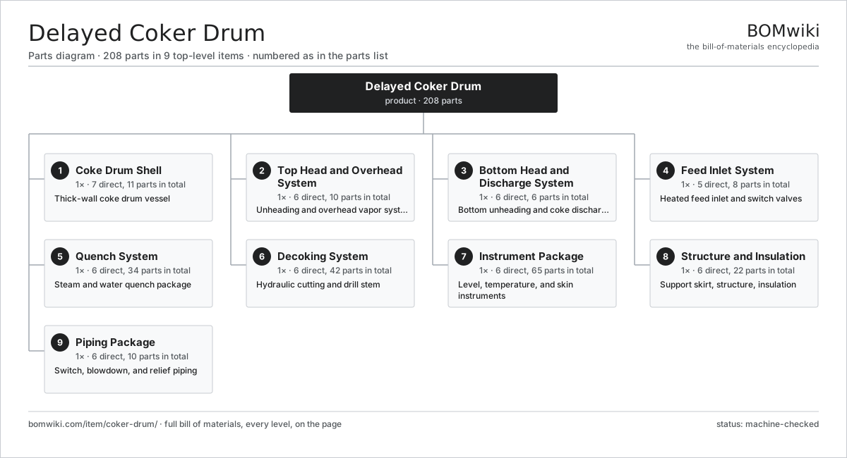
| # | Part | Qty | What it does |
|---|---|---|---|
| 1 | Coke Drum Shell 7 parts | 1× | Thick-wall coke drum vessel |
| 2 | Top Head and Overhead System 6 parts | 1× | Unheading and overhead vapor system |
| 3 | Bottom Head and Discharge System 6 parts | 1× | Bottom unheading and coke discharge |
| 4 | Feed Inlet System 5 parts | 1× | Heated feed inlet and switch valves |
| 5 | Quench System 6 parts | 1× | Steam and water quench package |
| 6 | Decoking System 6 parts | 1× | Hydraulic cutting and drill stem |
| 7 | Instrument Package 6 parts | 1× | Level, temperature, and skin instruments |
| 8 | Structure and Insulation 6 parts | 1× | Support skirt, structure, insulation |
| 9 | Piping Package 6 parts | 1× | Switch, blowdown, and relief piping |
3D model
No 3D model yet. Have a CAD file of this? Add a 3D model. STL renders right on this page; STEP, FreeCAD, and OpenSCAD sources are welcome too (openly licensed, like all 3D models on BOMwiki).
Build & assembly graph
expand / collapse · shared sub-assemblies converge · links to related products · est. labourTap an assembly to expand/collapse · tap a part to open it · use “Open page” for any node · drag to pan, scroll to zoom.
Bill of materials for Delayed Coker Drum
9 top-level lines · 79 rows shown · 208 parts total · indented to 3 levels| # | Item / sub-assembly | Part no. | Qty/assy | Ext. qty | Parts | Type |
|---|---|---|---|---|---|---|
| 1 | Coke Drum Shell 7 parts | coker-drum-shell | 1× | 1 | 11 | assembly |
| 1.1 | Shell Course | coker-shell-course | 5× | 5 | · | part |
| 1.2 | Skirt Attachment Forging | coker-skirt-attachment | 1× | 1 | · | part |
| 1.3 | Internal Cladding | coker-cladding | 1× | 1 | · | part |
| 1.4 | Top Head Flange | coker-top-flange | 1× | 1 | · | part |
| 1.5 | Bottom Head Flange | coker-bottom-flange | 1× | 1 | · | part |
| 1.6 | Nozzle Set | coker-nozzle-set | 1× | 1 | · | part |
| 1.7 | Refractory Anchor | coker-refractory-anchor | 1× | 1 | · | part |
| 2 | Top Head and Overhead System 6 parts | coker-top-head-system | 1× | 1 | 10 | assembly |
| 2.1 | Top Unheading Device | coker-top-unheading-valve | 1× | 1 | · | part |
| 2.2 | Overhead Transfer Line | coker-overhead-line | 1× | 1 | · | part |
| 2.3 | Overhead Quench Ring | coker-overhead-quench-ring | 1× | 1 | · | part |
| 2.4 | Overhead Isolation Valve | coker-spool-isolation-valve | 2× | 2 | · | part |
| 2.5 | Top Head Actuator | coker-top-head-actuator | 1× | 1 | · | part |
| 2.6 | O-Ring Set | oring-set | 4× | 4 | · | part |
| 3 | Bottom Head and Discharge System 6 parts | coker-bottom-head-system | 1× | 1 | 6 | assembly |
| 3.1 | Bottom Unheading Device | coker-bottom-unheading-valve | 1× | 1 | · | part |
| 3.2 | Discharge Chute | coker-discharge-chute | 1× | 1 | · | part |
| 3.3 | Bottom Head Actuator | coker-bottom-actuator | 1× | 1 | · | part |
| 3.4 | Bottom Isolation Valve | coker-bottom-isolation-valve | 1× | 1 | · | part |
| 3.5 | Unheading Seal | coker-deheading-seal | 1× | 1 | · | part |
| 3.6 | Fastener Set | fastener-set | 1× | 1 | · | part |
| 4 | Feed Inlet System 5 parts | coker-feed-inlet | 1× | 1 | 8 | assembly |
| 4.1 | Feed Switch Valve | coker-switch-valve | 2× | 2 | · | part |
| 4.2 | Inlet Spool | coker-inlet-spool | 1× | 1 | · | part |
| 4.3 | Warm-Up Line | coker-warmup-line | 1× | 1 | · | part |
| 4.4 | Feed Isolation Valve | coker-feed-isolation-valve | 2× | 2 | · | part |
| 4.5 | Switch Valve Actuator | coker-feed-actuator | 2× | 2 | · | part |
| 5 | Quench System 6 parts | coker-quench-system | 1× | 1 | 34 | assembly |
| 5.1 | Steam Quench Valve | coker-steam-quench-valve | 1× | 1 | · | part |
| 5.2 | Water Quench Valve | coker-water-quench-valve | 1× | 1 | · | part |
| 5.3 | Quench Distributor | coker-quench-distributor | 1× | 1 | · | part |
| 5.4 | Blowdown Line | coker-blowdown-line | 1× | 1 | · | part |
| 5.5 | Quench Pump 5 parts | coker-quench-pump | 1× | 1 | 29 | assembly |
| 5.5.1 | Pump Casing | coker-pump-casing | 1× | 1 | · | part |
| 5.5.2 | Pump Impeller | coker-pump-impeller | 1× | 1 | · | part |
| 5.5.3 | Pump Mechanical Seal | coker-pump-seal | 1× | 1 | · | part |
| 5.5.4 | Ball Bearing | ball-bearing | 2× | 2 | · | part |
| 5.5.5 | Servo Motor 4 parts + deeper › | servo-motor | 1× | 1 | 24 | assembly |
| 5.6 | Vent Valve | coker-vent-valve | 1× | 1 | · | part |
| 6 | Decoking System 6 parts | coker-decoking-system | 1× | 1 | 42 | assembly |
| 6.1 | Jet Water Pump 5 parts | coker-jet-pump | 1× | 1 | 37 | assembly |
| 6.1.1 | Pump Casing | coker-pump-casing | 1× | 1 | · | part |
| 6.1.2 | Pump Impeller | coker-pump-impeller | 6× | 6 | · | part |
| 6.1.3 | Pump Mechanical Seal | coker-pump-seal | 2× | 2 | · | part |
| 6.1.4 | Ball Bearing | ball-bearing | 4× | 4 | · | part |
| 6.1.5 | Servo Motor 4 parts + deeper › | servo-motor | 1× | 1 | 24 | assembly |
| 6.2 | Drill Stem | coker-drill-stem | 1× | 1 | · | part |
| 6.3 | Cutting Tool | coker-cutting-tool | 1× | 1 | · | part |
| 6.4 | Derrick Hoist | coker-hoist | 1× | 1 | · | part |
| 6.5 | Rotary Joint | coker-rotary-joint | 1× | 1 | · | part |
| 6.6 | Cutting Tool Valve | coker-jet-valve | 1× | 1 | · | part |
| 7 | Instrument Package 6 parts | coker-instrument-package | 1× | 1 | 65 | assembly |
| 7.1 | Neutron Level Detector | coker-level-detector | 1× | 1 | · | part |
| 7.2 | Skin Thermocouple | coker-skin-thermocouple | 12× | 12 | · | part |
| 7.3 | Temperature Element | coker-temperature-sensor | 6× | 6 | · | part |
| 7.4 | Pressure Sensor | pressure-sensor | 3× | 3 | · | part |
| 7.5 | Antifoam Injection Skid | coker-antifoam-injection | 1× | 1 | · | part |
| 7.6 | Control Panel 6 parts | coker-control-panel | 1× | 1 | 42 | assembly |
| 7.6.1 | Bare PCB | pcb-bare | 2× | 2 | · | part |
| 7.6.2 | Microcontroller | mcu | 2× | 2 | · | part |
| 7.6.3 | Relay | relay | 12× | 12 | · | part |
| 7.6.4 | Power Supply | power-supply | 1× | 1 | · | part |
| 7.6.5 | Connector | connector | 24× | 24 | · | part |
| 7.6.6 | Wire Bundle | wire-bundle | 1× | 1 | · | part |
| 8 | Structure and Insulation 6 parts | coker-structure | 1× | 1 | 22 | assembly |
| 8.1 | Support Skirt | coker-skirt | 1× | 1 | · | part |
| 8.2 | Structure Steel | coker-structure-steel | 1× | 1 | · | part |
| 8.3 | Access Platform | coker-platform | 6× | 6 | · | part |
| 8.4 | Thermal Insulation | coker-insulation | 1× | 1 | · | part |
| 8.5 | Sheet Metal Panel | sheet-panel | 12× | 12 | · | part |
| 8.6 | Fastener Set | fastener-set | 1× | 1 | · | part |
| 9 | Piping Package 6 parts | coker-piping-package | 1× | 1 | 10 | assembly |
| 9.1 | Process Piping | coker-process-piping | 1× | 1 | · | part |
| 9.2 | Relief Valve | coker-relief-valve | 2× | 2 | · | part |
| 9.3 | Blowdown Drum | coker-blowdown-drum | 1× | 1 | · | part |
| 9.4 | Check Valve | coker-check-valve | 3× | 3 | · | part |
| 9.5 | Expansion Joint | coker-expansion-joint | 2× | 2 | · | part |
| 9.6 | Fastener Set | fastener-set | 1× | 1 | · | part |
Related products
same domain, ranked by shared parts Amine Gas Sweetening Unit
3,543 parts · shares 14 with this page
CO2 Injection Pump
463 parts · shares 14 with this page
Amine Gas Sweetening Unit
3,543 parts · shares 14 with this page
CO2 Injection Pump
463 parts · shares 14 with this page
 Condensate Stabilizer Column
2,234 parts · shares 14 with this page
Condensate Stabilizer Column
2,234 parts · shares 14 with this page
 Drilling Mud Mixing System
135 parts · shares 14 with this page
Drilling Mud Mixing System
135 parts · shares 14 with this page
 Fired Process Heater
438 parts · shares 14 with this page
Fired Process Heater
438 parts · shares 14 with this page
 Oilwell Cementing Unit
902 parts · shares 14 with this page
Oilwell Cementing Unit
902 parts · shares 14 with this page
Sourcing: possible vendors
Browse the supplier directory → Prices, MOQ, and lead times are algorithmic estimates, not quotes, and not claims about these companies. Company mappings are curated by keyword; est. price band $10k–$50M. How estimates work| Vendor | HQ | Specialty | MOQ | Lead time |
|---|---|---|---|---|
|
🇺🇸SLB
slb.com ↗
|
Houston, US | Oilfield services & equipment | made to order | 24–48 wks |
| halliburton.com ↗ | Houston, US | Oilfield services | made to order | 24–48 wks |
| bakerhughes.com ↗ | Houston, US | Energy technology | made to order | 24–48 wks |
|
🇺🇸NOV
nov.com ↗
|
Houston, US | Drilling equipment | made to order | 24–48 wks |
| technipfmc.com ↗ | London, GB | Subsea & surface systems | made to order | 24–48 wks |
895-word article