Condensate Stabilizer Column
ProductOverview
A condensate stabilizer is a distillation column that turns raw gas condensate into a liquid that can be stored safely and shipped. Condensate dropping out of a gas stream is saturated with dissolved light ends, methane, ethane, propane and butane, which give it a high vapor pressure. Put into an atmospheric tank, that volatile liquid would flash and breathe large volumes of hydrocarbon vapor, losing product and creating a fire and emissions hazard. The stabilizer fractionates the condensate so the light ends leave overhead as gas while a stable, low-vapor-pressure liquid drops out the bottom, meeting a Reid vapor pressure spec of roughly 8 to 12 psi for storage and sale. A unit processes anywhere from 500 to 30,000 barrels per day.
The column works on the same principle as any distillation tower. Heat added at the Reboiler System boils the bottoms and sends vapor up the column; the rising vapor contacts descending liquid on each Fractionation Tray, stripping the volatile components upward. The lighter a component, the more it concentrates at the top; the heavier, the more it stays at the bottom. The art of stabilizer design is removing just enough light ends to hit the vapor pressure spec without boiling off valuable condensate.
Feed handling
Raw condensate arrives from upstream separators at varying rate and quality, so it first enters the Feed System. The Feed Surge Drum buffers the flow and lets any free water or gas separate. From there the feed passes through the Feed/Bottoms Exchanger, which preheats the cold feed against the hot stabilized product leaving the column bottom. This feed-bottoms exchange recovers heat that would otherwise be added at the reboiler and removed at the product cooler, and it is the main energy economy of the unit.
A stabilizer can run in two configurations. A reflux (cold-feed) column feeds the chilled condensate near the top and uses an overhead condenser and reflux to control the top temperature, giving a sharper separation and recovering more intermediate components into the bottoms. A reboiled stripper omits the overhead reflux and simply strips the feed with reboiler vapor, which is simpler but loses more of the intermediate range overhead. The choice depends on how much propane and butane the operator wants to keep in the liquid product.
Fractionation
The preheated feed enters the Stabilizer Column through the Feed Distributor. Inside, the Column Shell houses a stack of valve trays, each a vapor-liquid contact stage. On every tray, rising vapor bubbles through the Tray Valve openings into a pool of liquid held back by the Outlet Weir, exchanging components, and the liquid overflows down the Downcomer to the tray below. More trays give a sharper split between the light ends going overhead and the stabilized liquid going to the bottom.
The column operates at 100 to 400 psig. Higher pressure raises the bottom temperature needed to strip the light ends but reduces the overhead compression duty, so the pressure is set against the available reboiler heat and the downstream gas handling. The bottom temperature, held by the reboiler, is the master control: raise it and more light ends are driven overhead, lowering the product vapor pressure.
Reboiler and overhead
The Reboiler System supplies the heat that drives the separation. A Reboiler, fired by a Heat Medium System or heated by steam, boils a portion of the column bottoms and returns the vapor to the lowest tray. The reboiler duty sets how completely the light ends are stripped and therefore the product vapor pressure. Because the heat medium is fired, the heater carries a Burner Management System burner management system to NFPA 86 that proves the Flame Scanner flame before admitting fuel.
The light ends leaving the top enter the Overhead System. The Overhead Condenser cools the overhead vapor; in a reflux column the condensed liquid collects in the Reflux Accumulator Drum and the Reflux Pump returns a portion to the top tray as reflux to control the top temperature and sharpen the cut. The uncondensed gas, mostly methane through butane, goes to a compressor for sale or to the fuel header.
Product handling and pumps
The stabilized liquid leaving the bottom is hot, having given up heat to the feed in the Feed/Bottoms Exchanger, but still needs trimming before storage. The Product Cooler drops it to a safe storage temperature with an air cooler. The Pump Package then moves the product: a Product Transfer Pump with an installed spare transfers the stabilized liquid to tankage or pipeline. Each rotating pump carries a Mechanical Seal Cartridge to contain the hydrocarbon and runs on Ball Bearing supports.
Control and construction
The Control System holds the three interacting variables that set product quality: column pressure, reboiler bottom temperature and reflux rate. An on-line Vapor Pressure Analyzer measures the Reid vapor pressure of the stabilized product and closes the loop, trimming the reboiler duty to hold the spec as feed rate and composition drift. The vessels are protected against overpressure by Relief Valve devices sized to API 526.
Construction follows the service. The column shell and the warm vessels are carbon steel to ASME Section VIII, while the Tray Deck and internals are stainless because the wet, hot hydrocarbon environment with trace acid gas attacks carbon steel trays. The tall Column Shell mounts on a Support Structure of structural steel with access Access Platform levels, and the interconnecting Process Pipe Spool piping follows ASME B31.3. Heat exchangers are built to TEMA standards.
Condensate Stabilizer Column parts and their functions
8 top-level parts · 2,234 parts in total · full bill of materials below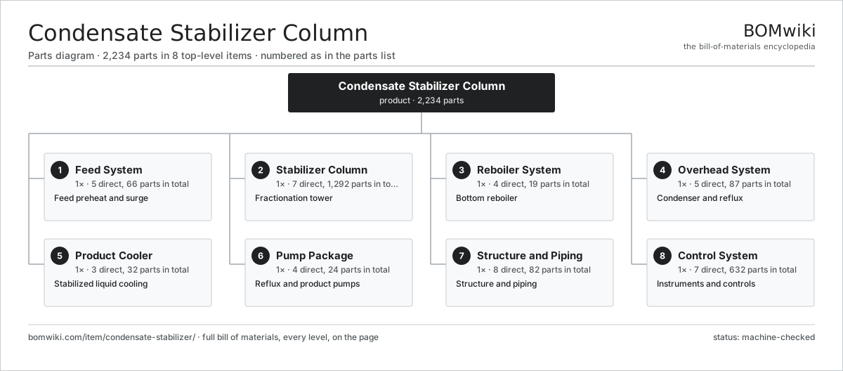
| # | Part | Qty | What it does |
|---|---|---|---|
| 1 | Feed System 5 parts | 1× | Feed preheat and surge |
| 2 | Stabilizer Column 7 parts | 1× | Fractionation tower |
| 3 | Reboiler System 4 parts | 1× | Bottom reboiler |
| 4 | Overhead System 5 parts | 1× | Condenser and reflux |
| 5 | Product Cooler 3 parts | 1× | Stabilized liquid cooling |
| 6 | Pump Package 4 parts | 1× | Reflux and product pumps |
| 7 | Structure and Piping 8 parts | 1× | Structure and piping |
| 8 | Control System 7 parts | 1× | Instruments and controls |
3D model
No 3D model yet. Have a CAD file of this? Add a 3D model. STL renders right on this page; STEP, FreeCAD, and OpenSCAD sources are welcome too (openly licensed, like all 3D models on BOMwiki).
Build & assembly graph
expand / collapse · shared sub-assemblies converge · links to related products · est. labourTap an assembly to expand/collapse · tap a part to open it · use “Open page” for any node · drag to pan, scroll to zoom.
Bill of materials for Condensate Stabilizer Column
8 top-level lines · 112 rows shown · 2,234 parts total · indented to 3 levels| # | Item / sub-assembly | Part no. | Qty/assy | Ext. qty | Parts | Type |
|---|---|---|---|---|---|---|
| 1 | Feed System 5 parts | cst-feed-system | 1× | 1 | 66 | assembly |
| 1.1 | Feed Surge Drum | cst-feed-surge-drum | 1× | 1 | · | part |
| 1.2 | Feed/Bottoms Exchanger 4 parts | cst-feed-bottoms-exchanger | 1× | 1 | 10 | assembly |
| 1.2.1 | Exchanger Shell | cst-exchanger-shell | 1× | 1 | · | part |
| 1.2.2 | Tube Bundle | cst-tube-bundle | 1× | 1 | · | part |
| 1.2.3 | Tubesheet | cst-tubesheet | 2× | 2 | · | part |
| 1.2.4 | Baffle Plate | cst-baffle | 6× | 6 | · | part |
| 1.3 | Feed Pump 4 parts | cst-feed-pump | 1× | 1 | 10 | assembly |
| 1.3.1 | Pump Hydraulic End | cst-pump-head | 1× | 1 | · | part |
| 1.3.2 | Pump Motor | cst-pump-motor | 1× | 1 | · | part |
| 1.3.3 | Mechanical Seal Cartridge 3 parts + deeper › | mechanical-seal-cartridge | 1× | 1 | 6 | assembly |
| 1.3.4 | Ball Bearing | ball-bearing | 2× | 2 | · | part |
| 1.4 | Level Control Loop 2 parts | cst-level-control | 1× | 1 | 44 | assembly |
| 1.4.1 | Level Transmitter 4 parts + deeper › | cst-level-transmitter | 1× | 1 | 43 | assembly |
| 1.4.2 | Level Control Valve | cst-level-valve | 1× | 1 | · | part |
| 1.5 | Pressure Sensor | pressure-sensor | 1× | 1 | · | part |
| 2 | Stabilizer Column 7 parts | cst-stabilizer-column | 1× | 1 | 1,292 | assembly |
| 2.1 | Column Shell | cst-column-shell | 1× | 1 | · | part |
| 2.2 | Fractionation Tray 4 parts | cst-tray | 24× | 24 | 53 | assembly |
| 2.2.1 | Tray Deck | cst-tray-deck | 1× | 24 | · | part |
| 2.2.2 | Tray Valve | cst-tray-valve | 50× | 1,200 | · | part |
| 2.2.3 | Downcomer | cst-downcomer | 1× | 24 | · | part |
| 2.2.4 | Outlet Weir | cst-weir | 1× | 24 | · | part |
| 2.3 | Feed Distributor | cst-feed-distributor | 1× | 1 | · | part |
| 2.4 | Reboiler Return Nozzle | cst-reboiler-return-nozzle | 1× | 1 | · | part |
| 2.5 | Internals Support Ring | cst-column-internals | 1× | 1 | · | part |
| 2.6 | Manway | cst-manway | 4× | 4 | · | part |
| 2.7 | Process Nozzle | cst-nozzle | 12× | 12 | · | part |
| 3 | Reboiler System 4 parts | cst-reboiler-system | 1× | 1 | 19 | assembly |
| 3.1 | Reboiler 4 parts | cst-reboiler | 1× | 1 | 4 | assembly |
| 3.1.1 | Reboiler Shell | cst-reboiler-shell | 1× | 1 | · | part |
| 3.1.2 | Tube Bundle | cst-tube-bundle | 1× | 1 | · | part |
| 3.1.3 | Reboiler Firetube | cst-reboiler-firetube | 1× | 1 | · | part |
| 3.1.4 | Heating Element | heating-element | 1× | 1 | · | part |
| 3.2 | Reboiler Circulation Pump 3 parts | cst-reboiler-pump | 1× | 1 | 4 | assembly |
| 3.2.1 | Pump Hydraulic End | cst-pump-head | 1× | 1 | · | part |
| 3.2.2 | Pump Motor | cst-pump-motor | 1× | 1 | · | part |
| 3.2.3 | Ball Bearing | ball-bearing | 2× | 2 | · | part |
| 3.3 | Heat Medium System 4 parts | cst-heat-medium-system | 1× | 1 | 9 | assembly |
| 3.3.1 | Fired Heater | cst-fired-heater | 1× | 1 | · | part |
| 3.3.2 | Gas Burner 3 parts + deeper › | cst-burner | 1× | 1 | 3 | assembly |
| 3.3.3 | Heat Medium Pump 3 parts + deeper › | cst-circulation-pump | 1× | 1 | 4 | assembly |
| 3.3.4 | Expansion Tank | cst-expansion-tank | 1× | 1 | · | part |
| 3.4 | RTD Temperature Probe | temperature-rtd | 2× | 2 | · | part |
| 4 | Overhead System 5 parts | cst-overhead-system | 1× | 1 | 87 | assembly |
| 4.1 | Overhead Condenser 3 parts | cst-overhead-condenser | 1× | 1 | 31 | assembly |
| 4.1.1 | Exchanger Shell | cst-exchanger-shell | 1× | 1 | · | part |
| 4.1.2 | Tube Bundle | cst-tube-bundle | 1× | 1 | · | part |
| 4.1.3 | Air Cooler Fan 3 parts + deeper › | cst-cooling-fan | 1× | 1 | 29 | assembly |
| 4.2 | Reflux Accumulator Drum | cst-reflux-drum | 1× | 1 | · | part |
| 4.3 | Reflux Pump 4 parts | cst-reflux-pump | 1× | 1 | 10 | assembly |
| 4.3.1 | Pump Hydraulic End | cst-pump-head | 1× | 1 | · | part |
| 4.3.2 | Pump Motor | cst-pump-motor | 1× | 1 | · | part |
| 4.3.3 | Mechanical Seal Cartridge 3 parts + deeper › | mechanical-seal-cartridge | 1× | 1 | 6 | assembly |
| 4.3.4 | Ball Bearing | ball-bearing | 2× | 2 | · | part |
| 4.4 | Overhead Trim Cooler | cst-overhead-cooler | 1× | 1 | · | part |
| 4.5 | Level Control Loop 2 parts | cst-level-control | 1× | 1 | 44 | assembly |
| 4.5.1 | Level Transmitter 4 parts + deeper › | cst-level-transmitter | 1× | 1 | 43 | assembly |
| 4.5.2 | Level Control Valve | cst-level-valve | 1× | 1 | · | part |
| 5 | Product Cooler 3 parts | cst-product-cooler | 1× | 1 | 32 | assembly |
| 5.1 | Product Air Cooler 2 parts | cst-product-air-cooler | 1× | 1 | 2 | assembly |
| 5.1.1 | Finned Tube Bundle | cst-cooler-tube-bundle | 1× | 1 | · | part |
| 5.1.2 | Cooler Frame | cst-cooler-frame | 1× | 1 | · | part |
| 5.2 | Air Cooler Fan 3 parts | cst-cooling-fan | 1× | 1 | 29 | assembly |
| 5.2.1 | Fan Blade | cst-fan-blade | 4× | 4 | · | part |
| 5.2.2 | Servo Motor 4 parts + deeper › | servo-motor | 1× | 1 | 24 | assembly |
| 5.2.3 | Fan Hub | cst-fan-hub | 1× | 1 | · | part |
| 5.3 | Finned Tube Bundle | cst-cooler-tube-bundle | 1× | 1 | · | part |
| 6 | Pump Package 4 parts | cst-pump-package | 1× | 1 | 24 | assembly |
| 6.1 | Product Transfer Pump 3 parts | cst-product-pump | 2× | 2 | 4 | assembly |
| 6.1.1 | Pump Hydraulic End | cst-pump-head | 1× | 2 | · | part |
| 6.1.2 | Pump Motor | cst-pump-motor | 1× | 2 | · | part |
| 6.1.3 | Ball Bearing | ball-bearing | 2× | 4 | · | part |
| 6.2 | Pump Baseplate | cst-pump-baseplate | 2× | 2 | · | part |
| 6.3 | Flexible Coupling | cst-pump-coupling | 2× | 2 | · | part |
| 6.4 | Mechanical Seal Cartridge 3 parts | mechanical-seal-cartridge | 2× | 2 | 6 | assembly |
| 6.4.1 | Seal Face Set | atu-seal-face-set | 1× | 2 | · | part |
| 6.4.2 | Coil Spring | coil-spring | 4× | 8 | · | part |
| 6.4.3 | O-Ring Set | oring-set | 1× | 2 | · | part |
| 7 | Structure and Piping 8 parts | cst-skid-base | 1× | 1 | 82 | assembly |
| 7.1 | Support Structure | cst-support-structure | 1× | 1 | · | part |
| 7.2 | Access Platform | cst-platform | 2× | 2 | · | part |
| 7.3 | Process Pipe Spool | cst-pipe-spool | 1× | 1 | · | part |
| 7.4 | Pipe Flange | cst-pipe-flange | 36× | 36 | · | part |
| 7.5 | Control Valve 4 parts | cst-control-valve | 4× | 4 | 6 | assembly |
| 7.5.1 | Valve Body | cst-valve-body | 1× | 4 | · | part |
| 7.5.2 | Valve Trim | cst-valve-trim | 1× | 4 | · | part |
| 7.5.3 | Valve Actuator 3 parts + deeper › | cst-valve-actuator | 1× | 4 | 3 | assembly |
| 7.5.4 | O-Ring Set | oring-set | 1× | 4 | · | part |
| 7.6 | Relief Valve | cst-relief-valve | 3× | 3 | · | part |
| 7.7 | Block Valve | cst-block-valve | 14× | 14 | · | part |
| 7.8 | Fastener Set | fastener-set | 1× | 1 | · | part |
| 8 | Control System 7 parts | cst-control-system | 1× | 1 | 632 | assembly |
| 8.1 | Control Panel 4 parts | cst-control-panel | 1× | 1 | 561 | assembly |
| 8.1.1 | Sheet Metal Panel | sheet-panel | 1× | 1 | · | part |
| 8.1.2 | Relay | relay | 8× | 8 | · | part |
| 8.1.3 | Control I/O Card 4 parts + deeper › | cst-io-card | 6× | 6 | 86 | assembly |
| 8.1.4 | Terminal Block | cst-terminal-block | 36× | 36 | · | part |
| 8.2 | Vapor Pressure Analyzer 4 parts | cst-rvp-analyzer | 1× | 1 | 53 | assembly |
| 8.2.1 | Bare PCB | pcb-bare | 1× | 1 | · | part |
| 8.2.2 | Microcontroller | mcu | 1× | 1 | · | part |
| 8.2.3 | Pressure Sensor | pressure-sensor | 1× | 1 | · | part |
| 8.2.4 | SMD Passive (R/C/L) | smd-passives | 50× | 50 | · | part |
| 8.3 | Burner Management System 4 parts | cst-bms | 1× | 1 | 7 | assembly |
| 8.3.1 | Bare PCB | pcb-bare | 1× | 1 | · | part |
| 8.3.2 | Microcontroller | mcu | 1× | 1 | · | part |
| 8.3.3 | Flame Scanner | cst-flame-scanner | 1× | 1 | · | part |
| 8.3.4 | Relay | relay | 4× | 4 | · | part |
| 8.4 | Pressure Sensor | pressure-sensor | 5× | 5 | · | part |
| 8.5 | RTD Temperature Probe | temperature-rtd | 4× | 4 | · | part |
| 8.6 | Power Supply | power-supply | 1× | 1 | · | part |
| 8.7 | Wire Bundle | wire-bundle | 1× | 1 | · | part |
Related products
same domain, ranked by shared parts Amine Gas Sweetening Unit
3,543 parts · shares 20 with this page
Amine Gas Sweetening Unit
3,543 parts · shares 20 with this page
 Wireline Logging Unit
189 parts · shares 17 with this page
JT Gas Dew Point Skid
441 parts · shares 8 with this page
LACT Custody Transfer Unit
554 parts · shares 8 with this page
TEG Gas Dehydration Skid
587 parts · shares 7 with this page
Wireline Logging Unit
189 parts · shares 17 with this page
JT Gas Dew Point Skid
441 parts · shares 8 with this page
LACT Custody Transfer Unit
554 parts · shares 8 with this page
TEG Gas Dehydration Skid
587 parts · shares 7 with this page
 Sulfur Recovery Unit
206 parts · shares 15 with this page
Sulfur Recovery Unit
206 parts · shares 15 with this page
Sourcing: possible vendors
Browse the supplier directory → Prices, MOQ, and lead times are algorithmic estimates, not quotes, and not claims about these companies. Company mappings are curated by keyword; est. price band $10k–$50M. How estimates work| Vendor | HQ | Specialty | MOQ | Lead time |
|---|---|---|---|---|
|
🇺🇸SLB
slb.com ↗
|
Houston, US | Oilfield services & equipment | made to order | 24–48 wks |
| halliburton.com ↗ | Houston, US | Oilfield services | made to order | 24–48 wks |
| bakerhughes.com ↗ | Houston, US | Energy technology | made to order | 24–48 wks |
|
🇺🇸NOV
nov.com ↗
|
Houston, US | Drilling equipment | made to order | 24–48 wks |
| technipfmc.com ↗ | London, GB | Subsea & surface systems | made to order | 24–48 wks |
942-word article