Sulfur Recovery Unit
ProductOverview
A sulfur recovery unit, or SRU, removes hydrogen sulfide from refinery and gas-plant streams and converts it into salable elemental sulfur. The acid gas feed comes from amine regeneration and sour water stripping, where it has already been concentrated to 40 to 90 percent H2S. The unit runs on the modified Claus process, which pairs a high-temperature thermal stage with two or three catalytic stages. A single train recovers 95 to 98 percent of the inbound sulfur, and an added tail gas treating step pushes total recovery to about 99.9 percent so the plant meets SO2 emission limits at the stack. Capacities span roughly 10 t/d on a small gas plant to 2,000 t/d on a large refinery complex.
Thermal stage
The acid gas enters the Reaction Furnace through the Main Acid Gas Burner, where it mixes with a controlled stream of combustion air. Roughly one third of the H2S burns to SO2 while the rest passes through unreacted. Flame temperature sits between 980 and 1,370 C depending on feed richness, and a checker wall extends residence time so that part of the Claus reaction completes thermally and contaminants such as ammonia and BTEX are destroyed. Combustion air comes from the Combustion Air Blower, a centrifugal machine whose inlet vanes trim flow to hold the burner stoichiometry. Hot effluent leaves the furnace and enters the Waste Heat Boiler, a fire-tube boiler that cools the gas to about 320 C and raises 40 to 45 barg steam for the rest of the plant. Ceramic ferrules protect the inlet tube ends, which see the harshest thermal shock in the unit.
Catalytic stages
After the first sulfur condenser, the gas is too cool to react further, so it passes through a Reheater that lifts it back above the sulfur dew point. The Catalytic Converter then runs the equilibrium reaction 2 H2S + SO2 to 3 S + 2 H2O over a bed of activated alumina or titania at 200 to 340 C. Each pass converts a further fraction of the remaining sulfur species, so the stages are arranged in series with a reheater and a condenser between them. Two stages are common, and a third stage is added when the recovery target is high or the feed is lean. Titania catalyst is used in the first bed where it also hydrolyzes COS and CS2, two species that alumina alone leaves behind. Bed thermowells track the exotherm, which is the operator's first warning of catalyst deactivation or sulfation.
Sulfur condensation and handling
A Sulfur Condenser follows the furnace and each catalytic stage. It is a shell-and-tube exchanger that cools the process gas below 160 C on the tube side while raising 3.5 to 4.5 barg steam on the shell side. Liquid sulfur forms on the tubes, collects in the bottom channel, and drains through a steam-jacketed seal leg. A demister pad at the outlet captures entrained mist so it does not carry forward and foul the next bed. All condenser drains route to the Sulfur Pit, a steam-jacketed pit that holds the product molten at 135 to 150 C. The pit includes a degassing section that strips dissolved H2S and polysulfides down below 10 ppm, which makes the sulfur safe to store and ship. A submerged Sulfur Export Pump exports the finished product to storage or to loading.
Tail gas treatment
The gas leaving the last condenser still carries a few percent of the original sulfur as unconverted H2S, SO2, and sulfur vapor. In its simplest form the SRU sends this stream to the Tail Gas Incinerator, a thermal oxidizer that burns everything to SO2 at 540 to 760 C before the stack, with continuous SO2 monitoring on the discharge. When the site cannot meet emission limits on the Claus train alone, an upstream amine-based tail gas unit hydrogenates the residual sulfur species back to H2S and recycles them to the front of the SRU, which is what lifts overall recovery to 99.9 percent.
Materials and construction
Vessels that see flame or hot gas are carbon steel with internal refractory, so the steel stays cool while the lining takes the heat. The Reheater coils, condenser bundles, and converter internals use 304 or 321 stainless to resist sulfidation and wet acid attack during shutdowns. Vessels are built to ASME Section VIII Division 1, fired equipment follows API 560, and pressure relief is sized per API 521. Every sulfur-wetted line is steam jacketed or heat traced, because sulfur solidifies near 115 C and a cold plug can block a drain and trip the unit.
Control and applications
Stable recovery depends on holding the tail gas at a 2 to 1 ratio of H2S to SO2, which is the stoichiometric Claus balance. The Control System reads that ratio with a dedicated analyzer and trims combustion air through the blower vanes, a scheme known as air-demand control. Distributed Pressure Sensor transmitters, bed temperatures, and flame scanners feed the safety logic that shuts the unit down on loss of flame or feed. SRUs are standard equipment at refineries, sour gas processing plants, and coke gasification facilities, anywhere H2S must be removed and turned into a stable, transportable product rather than vented.
Sulfur Recovery Unit parts and their functions
9 top-level parts · 206 parts in total · full bill of materials below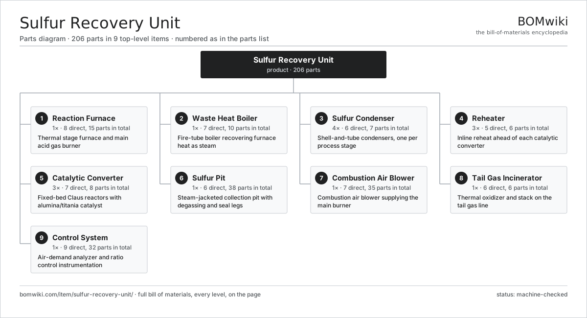
| # | Part | Qty | What it does |
|---|---|---|---|
| 1 | Reaction Furnace 8 parts | 1× | Thermal stage furnace and main acid gas burner |
| 2 | Waste Heat Boiler 7 parts | 1× | Fire-tube boiler recovering furnace heat as steam |
| 3 | Sulfur Condenser 6 parts | 4× | Shell-and-tube condensers, one per process stage |
| 4 | Reheater 5 parts | 3× | Inline reheat ahead of each catalytic converter |
| 5 | Catalytic Converter 7 parts | 3× | Fixed-bed Claus reactors with alumina/titania catalyst |
| 6 | Sulfur Pit 6 parts | 1× | Steam-jacketed collection pit with degassing and seal legs |
| 7 | Combustion Air Blower 7 parts | 1× | Combustion air blower supplying the main burner |
| 8 | Tail Gas Incinerator 6 parts | 1× | Thermal oxidizer and stack on the tail gas line |
| 9 | Control System 9 parts | 1× | Air-demand analyzer and ratio control instrumentation |
3D model
No 3D model yet. Have a CAD file of this? Add a 3D model. STL renders right on this page; STEP, FreeCAD, and OpenSCAD sources are welcome too (openly licensed, like all 3D models on BOMwiki).
Build & assembly graph
expand / collapse · shared sub-assemblies converge · links to related products · est. labourTap an assembly to expand/collapse · tap a part to open it · use “Open page” for any node · drag to pan, scroll to zoom.
Bill of materials for Sulfur Recovery Unit
9 top-level lines · 85 rows shown · 206 parts total · indented to 3 levels| # | Item / sub-assembly | Part no. | Qty/assy | Ext. qty | Parts | Type |
|---|---|---|---|---|---|---|
| 1 | Reaction Furnace 8 parts | sulfur-recovery-unit-reaction-furnace | 1× | 1 | 15 | assembly |
| 1.1 | Furnace Shell | sulfur-recovery-unit-furnace-shell | 1× | 1 | · | part |
| 1.2 | Refractory Lining | sulfur-recovery-unit-refractory-lining | 1× | 1 | · | part |
| 1.3 | Main Acid Gas Burner 5 parts | sulfur-recovery-unit-main-burner | 1× | 1 | 5 | assembly |
| 1.3.1 | Burner Block | sulfur-recovery-unit-burner-block | 1× | 1 | · | part |
| 1.3.2 | Burner Nozzle | sulfur-recovery-unit-burner-nozzle | 1× | 1 | · | part |
| 1.3.3 | Air Register | sulfur-recovery-unit-air-register | 1× | 1 | · | part |
| 1.3.4 | Ignition Electrode | sulfur-recovery-unit-ignition-electrode | 1× | 1 | · | part |
| 1.3.5 | Fastener Set | fastener-set | 1× | 1 | · | part |
| 1.4 | Checker Wall | sulfur-recovery-unit-checker-wall | 1× | 1 | · | part |
| 1.5 | Pilot Burner | sulfur-recovery-unit-pilot-burner | 1× | 1 | · | part |
| 1.6 | Flame Scanner | sulfur-recovery-unit-flame-scanner | 2× | 2 | · | part |
| 1.7 | Inspection Peephole | sulfur-recovery-unit-peephole | 2× | 2 | · | part |
| 1.8 | Pressure Sensor | pressure-sensor | 2× | 2 | · | part |
| 2 | Waste Heat Boiler 7 parts | sulfur-recovery-unit-waste-heat-boiler | 1× | 1 | 10 | assembly |
| 2.1 | Boiler Shell | sulfur-recovery-unit-whb-shell | 1× | 1 | · | part |
| 2.2 | Boiler Tube Bundle | sulfur-recovery-unit-whb-tube-bundle | 1× | 1 | · | part |
| 2.3 | Boiler Tube Sheet | sulfur-recovery-unit-whb-tube-sheet | 2× | 2 | · | part |
| 2.4 | Ceramic Ferrule Set | sulfur-recovery-unit-ferrule-set | 1× | 1 | · | part |
| 2.5 | Steam Drum Internals | sulfur-recovery-unit-steam-drum-internals | 1× | 1 | · | part |
| 2.6 | Steam Safety Valve | sulfur-recovery-unit-safety-valve | 2× | 2 | · | part |
| 2.7 | Pressure Sensor | pressure-sensor | 2× | 2 | · | part |
| 3 | Sulfur Condenser 6 parts | sulfur-recovery-unit-sulfur-condenser | 4× | 4 | 7 | assembly |
| 3.1 | Condenser Shell | sulfur-recovery-unit-condenser-shell | 1× | 4 | · | part |
| 3.2 | Condenser Tube Bundle | sulfur-recovery-unit-condenser-tube-bundle | 1× | 4 | · | part |
| 3.3 | Condenser Tube Sheet | sulfur-recovery-unit-condenser-tube-sheet | 2× | 8 | · | part |
| 3.4 | Sulfur Drain | sulfur-recovery-unit-sulfur-drain | 1× | 4 | · | part |
| 3.5 | Demister Pad | sulfur-recovery-unit-demister-pad | 1× | 4 | · | part |
| 3.6 | O-Ring Set | oring-set | 1× | 4 | · | part |
| 4 | Reheater 5 parts | sulfur-recovery-unit-reheater | 3× | 3 | 6 | assembly |
| 4.1 | Reheater Shell | sulfur-recovery-unit-reheater-shell | 1× | 3 | · | part |
| 4.2 | Reheat Coil | sulfur-recovery-unit-reheat-coil | 1× | 3 | · | part |
| 4.3 | Heating Element | heating-element | 2× | 6 | · | part |
| 4.4 | Hot Gas Bypass Damper | sulfur-recovery-unit-bypass-damper | 1× | 3 | · | part |
| 4.5 | Pressure Sensor | pressure-sensor | 1× | 3 | · | part |
| 5 | Catalytic Converter 7 parts | sulfur-recovery-unit-catalytic-converter | 3× | 3 | 8 | assembly |
| 5.1 | Converter Vessel | sulfur-recovery-unit-converter-vessel | 1× | 3 | · | part |
| 5.2 | Claus Catalyst Bed | sulfur-recovery-unit-catalyst-bed | 1× | 3 | · | part |
| 5.3 | Catalyst Support Grid | sulfur-recovery-unit-catalyst-support-grid | 1× | 3 | · | part |
| 5.4 | Gas Distributor | sulfur-recovery-unit-gas-distributor | 1× | 3 | · | part |
| 5.5 | Bed Thermowell Set | sulfur-recovery-unit-thermowell-set | 1× | 3 | · | part |
| 5.6 | Reactor Manway | sulfur-recovery-unit-manway | 1× | 3 | · | part |
| 5.7 | Pressure Sensor | pressure-sensor | 2× | 6 | · | part |
| 6 | Sulfur Pit 6 parts | sulfur-recovery-unit-sulfur-pit | 1× | 1 | 38 | assembly |
| 6.1 | Pit Liner | sulfur-recovery-unit-pit-liner | 1× | 1 | · | part |
| 6.2 | Pit Steam Coil | sulfur-recovery-unit-steam-coil | 1× | 1 | · | part |
| 6.3 | Degassing Column | sulfur-recovery-unit-degassing-column | 1× | 1 | · | part |
| 6.4 | Sulfur Export Pump 6 parts | sulfur-recovery-unit-sulfur-pump | 1× | 1 | 30 | assembly |
| 6.4.1 | Pump Casing | sulfur-recovery-unit-pump-casing | 1× | 1 | · | part |
| 6.4.2 | Pump Impeller | sulfur-recovery-unit-pump-impeller | 1× | 1 | · | part |
| 6.4.3 | Pump Column Shaft | sulfur-recovery-unit-pump-shaft | 1× | 1 | · | part |
| 6.4.4 | Ball Bearing | ball-bearing | 2× | 2 | · | part |
| 6.4.5 | Oil Seal | oil-seal | 1× | 1 | · | part |
| 6.4.6 | Servo Motor 4 parts + deeper › | servo-motor | 1× | 1 | 24 | assembly |
| 6.5 | Seal Leg | sulfur-recovery-unit-seal-leg | 4× | 4 | · | part |
| 6.6 | Pit Vent Ejector | sulfur-recovery-unit-pit-vent-ejector | 1× | 1 | · | part |
| 7 | Combustion Air Blower 7 parts | sulfur-recovery-unit-air-blower | 1× | 1 | 35 | assembly |
| 7.1 | Blower Casing | sulfur-recovery-unit-blower-casing | 1× | 1 | · | part |
| 7.2 | Blower Impeller | sulfur-recovery-unit-blower-impeller | 1× | 1 | · | part |
| 7.3 | Blower Shaft | sulfur-recovery-unit-blower-shaft | 1× | 1 | · | part |
| 7.4 | Blower Drive Motor 4 parts | sulfur-recovery-unit-blower-motor | 1× | 1 | 25 | assembly |
| 7.4.1 | Stator Assembly 3 parts + deeper › | stator-assembly | 1× | 1 | 3 | assembly |
| 7.4.2 | Rotor Assembly 4 parts + deeper › | rotor-assembly | 1× | 1 | 19 | assembly |
| 7.4.3 | Ball Bearing | ball-bearing | 2× | 2 | · | part |
| 7.4.4 | Motor Frame | sulfur-recovery-unit-motor-frame | 1× | 1 | · | part |
| 7.5 | Inlet Guide Vane | sulfur-recovery-unit-inlet-vane | 1× | 1 | · | part |
| 7.6 | Ball Bearing | ball-bearing | 2× | 2 | · | part |
| 7.7 | Coil Spring | coil-spring | 4× | 4 | · | part |
| 8 | Tail Gas Incinerator 6 parts | sulfur-recovery-unit-tail-gas-incinerator | 1× | 1 | 6 | assembly |
| 8.1 | Incinerator Shell | sulfur-recovery-unit-incinerator-shell | 1× | 1 | · | part |
| 8.2 | Incinerator Burner | sulfur-recovery-unit-incinerator-burner | 1× | 1 | · | part |
| 8.3 | Discharge Stack | sulfur-recovery-unit-stack | 1× | 1 | · | part |
| 8.4 | Forced Draft Fan | sulfur-recovery-unit-fd-fan | 1× | 1 | · | part |
| 8.5 | Flame Scanner | sulfur-recovery-unit-flame-scanner | 1× | 1 | · | part |
| 8.6 | Pressure Sensor | pressure-sensor | 1× | 1 | · | part |
| 9 | Control System 9 parts | sulfur-recovery-unit-control-system | 1× | 1 | 32 | assembly |
| 9.1 | Analyzer Cabinet | sulfur-recovery-unit-analyzer-cabinet | 1× | 1 | · | part |
| 9.2 | Controller Cabinet | sulfur-recovery-unit-controller-cabinet | 1× | 1 | · | part |
| 9.3 | Bare PCB | pcb-bare | 2× | 2 | · | part |
| 9.4 | Microcontroller | mcu | 2× | 2 | · | part |
| 9.5 | Relay | relay | 8× | 8 | · | part |
| 9.6 | Power Supply | power-supply | 1× | 1 | · | part |
| 9.7 | Connector | connector | 12× | 12 | · | part |
| 9.8 | Wire Bundle | wire-bundle | 1× | 1 | · | part |
| 9.9 | Pressure Sensor | pressure-sensor | 4× | 4 | · | part |
Related products
same domain, ranked by shared parts Wireline Logging Unit
189 parts · shares 16 with this page
Wireline Logging Unit
189 parts · shares 16 with this page
 Amine Gas Sweetening Unit
3,543 parts · shares 15 with this page
Amine Gas Sweetening Unit
3,543 parts · shares 15 with this page
 Condensate Stabilizer Column
2,234 parts · shares 15 with this page
Condensate Stabilizer Column
2,234 parts · shares 15 with this page
 Shale Shaker
201 parts · shares 15 with this page
Shale Shaker
201 parts · shares 15 with this page
 Deepwater Drillship
891,301 parts · shares 12 with this page
CO2 Injection Pump
463 parts · shares 14 with this page
Deepwater Drillship
891,301 parts · shares 12 with this page
CO2 Injection Pump
463 parts · shares 14 with this page
Sourcing: possible vendors
Browse the supplier directory → Prices, MOQ, and lead times are algorithmic estimates, not quotes, and not claims about these companies. Company mappings are curated by keyword; est. price band $10k–$50M. How estimates work| Vendor | HQ | Specialty | MOQ | Lead time |
|---|---|---|---|---|
|
🇺🇸SLB
slb.com ↗
|
Houston, US | Oilfield services & equipment | made to order | 24–48 wks |
| halliburton.com ↗ | Houston, US | Oilfield services | made to order | 24–48 wks |
| bakerhughes.com ↗ | Houston, US | Energy technology | made to order | 24–48 wks |
|
🇺🇸NOV
nov.com ↗
|
Houston, US | Drilling equipment | made to order | 24–48 wks |
| technipfmc.com ↗ | London, GB | Subsea & surface systems | made to order | 24–48 wks |
912-word article