Nitrogen Rejection Unit
ProductOverview
A nitrogen rejection unit, or NRU, separates nitrogen from natural gas so that the methane meets pipeline specification. Many gas reservoirs, especially older fields under nitrogen injection for enhanced recovery, produce gas with too much nitrogen to sell directly. Pipeline tariffs usually cap inert content at around 4 mol percent because nitrogen lowers the heating value and takes up compression and transport capacity without delivering energy. The NRU shown here uses cryogenic distillation, the most common method once nitrogen content rises above roughly 10 percent, where it is more economical than membrane or adsorption alternatives.
The unit chills the gas until methane and nitrogen separate by their different boiling points. At cryogenic temperatures methane condenses while nitrogen stays largely vapor, and a distillation column sharpens that split into a methane-rich liquid product and a nitrogen-rich vent. Reaching minus 170 C without freezing anything solid is the central engineering challenge, which is why the gas passes through extensive cleanup before it ever enters the Cold Box.
How it works
Feed gas first passes through the Feed Gas Treatment section. Free liquids drop out in the Inlet Separator, carbon dioxide is scrubbed in the Amine Contactor, and the gas is dried to below 0.1 ppmv water in the Molecular Sieve Bed. A Mercury Removal Bed then captures trace mercury that would otherwise attack the aluminum exchangers. These steps matter because water, CO2, and heavy hydrocarbons all freeze solid at cryogenic temperature and would plug the cold box within hours.
Inside the cold box the Main Heat Exchanger, a brazed aluminum plate-fin block, cools the incoming feed against the cold product and reject streams leaving the plant. This counter-current recovery is what makes the process efficient: most of the cold is recycled rather than supplied from outside. Final cooling and the cold needed to overcome losses come from the Turboexpander Package and a supplemental Refrigeration Package loop. The chilled, partly condensed feed enters the Distillation Section section.
Subsystems
The distillation section is the separation heart. A double-column arrangement is common: the High-Pressure Column does the bulk split at elevated pressure, and the Low-Pressure Column polishes the methane to specification at low pressure. The two are thermally linked by a Condenser-Reboiler that condenses nitrogen overhead in one column while reboiling methane in the other, so heat moves between them instead of being wasted. Structured Packing provides the vapor-liquid contact area, and a Cryogenic Reflux Pump returns reflux from the Reflux Drum.
Refrigeration is generated mainly by the Turboexpander Package. Gas expands across the Expander Wheel, doing work that drops its temperature far more efficiently than a simple Joule-Thomson Valve throttle. The work is recovered by the Booster Compressor Wheel on the same shaft, which recompresses gas and reduces the load on the main machines. The methane product leaves the cold box near atmospheric pressure, so the Product Recompression train, built around a Product Compressor, raises it back to pipeline pressure. The whole plant runs under the Control and Safety System, which includes online Gas Analyzer instruments confirming the product stays on spec.
Materials
Cold-end equipment is built almost entirely from aluminum and austenitic stainless steel because ordinary carbon steel becomes brittle below about minus 30 C. The main exchanger and packing are brazed aluminum, light and highly conductive. Cryogenic piping and column shells are stainless. The Expander Wheel is a titanium alloy to handle high tip speed at low temperature. Vessels exposed to ambient temperature in the feed treatment and recompression sections use carbon and low-alloy steel, which is cheaper where embrittlement is not a concern.
Variants
Single-column designs suit lower nitrogen content and lower methane recovery, while double-column designs reach 99 percent recovery at higher inert levels. Plants that also want to capture the nitrogen for reinjection or for liquid nitrogen sale add a purification column on the reject stream. The refrigeration source varies: small units may rely entirely on the turboexpander, while larger units add a closed Refrigeration Package loop using propane or a mixed refrigerant. Where helium is present in the feed, the NRU is often paired with a downstream helium recovery unit, since the cryogenic temperatures already concentrate helium in the nitrogen reject.
Applications
NRUs are installed at gas processing plants treating high-nitrogen reservoirs, at fields under nitrogen flooding for enhanced oil recovery, and at storage caverns where cushion gas mixes with product. They let otherwise unsalable gas reach the pipeline grid. Because the cold box cannot tolerate a freeze, operation centers on protecting the Feed Gas Treatment beds and watching the analyzers; an upset that lets water or CO2 slip through can force a multi-day warm-up and thaw to clear plugging before the unit can restart.
Nitrogen Rejection Unit parts and their functions
8 top-level parts · 87 parts in total · full bill of materials below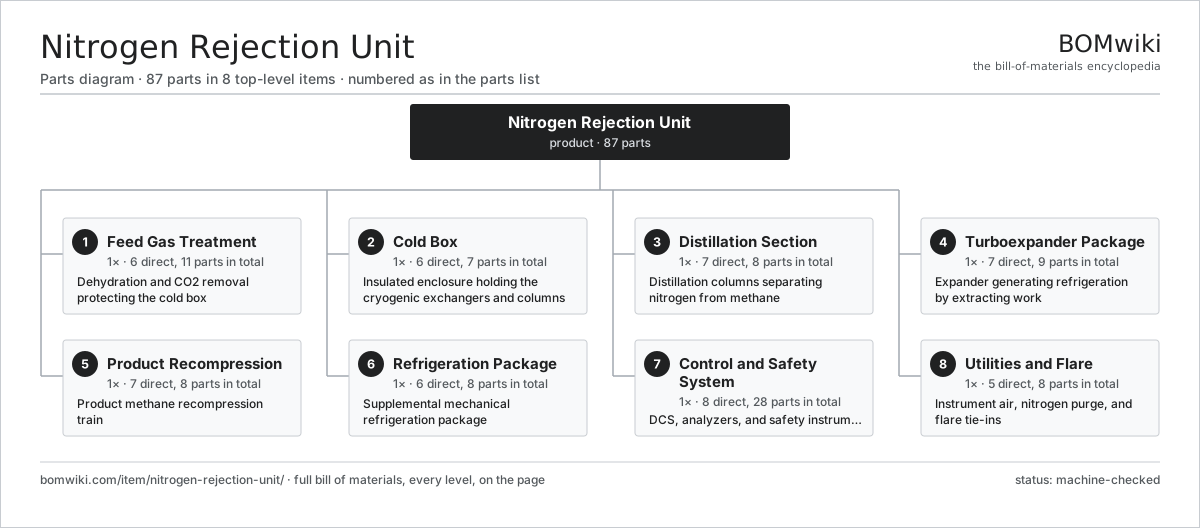
| # | Part | Qty | What it does |
|---|---|---|---|
| 1 | Feed Gas Treatment 6 parts | 1× | Dehydration and CO2 removal protecting the cold box |
| 2 | Cold Box 6 parts | 1× | Insulated enclosure holding the cryogenic exchangers and columns |
| 3 | Distillation Section 7 parts | 1× | Distillation columns separating nitrogen from methane |
| 4 | Turboexpander Package 7 parts | 1× | Expander generating refrigeration by extracting work |
| 5 | Product Recompression 7 parts | 1× | Product methane recompression train |
| 6 | Refrigeration Package 6 parts | 1× | Supplemental mechanical refrigeration package |
| 7 | Control and Safety System 8 parts | 1× | DCS, analyzers, and safety instrumented system |
| 8 | Utilities and Flare 5 parts | 1× | Instrument air, nitrogen purge, and flare tie-ins |
3D model
No 3D model yet. Have a CAD file of this? Add a 3D model. STL renders right on this page; STEP, FreeCAD, and OpenSCAD sources are welcome too (openly licensed, like all 3D models on BOMwiki).
Build & assembly graph
expand / collapse · shared sub-assemblies converge · links to related products · est. labourTap an assembly to expand/collapse · tap a part to open it · use “Open page” for any node · drag to pan, scroll to zoom.
Bill of materials for Nitrogen Rejection Unit
8 top-level lines · 60 rows shown · 87 parts total · indented to 3 levels| # | Item / sub-assembly | Part no. | Qty/assy | Ext. qty | Parts | Type |
|---|---|---|---|---|---|---|
| 1 | Feed Gas Treatment 6 parts | nitrogen-rejection-unit-feed-treatment | 1× | 1 | 11 | assembly |
| 1.1 | Inlet Separator | nitrogen-rejection-unit-inlet-separator | 1× | 1 | · | part |
| 1.2 | Amine Contactor | nitrogen-rejection-unit-amine-contactor | 1× | 1 | · | part |
| 1.3 | Molecular Sieve Bed | nitrogen-rejection-unit-mol-sieve-bed | 2× | 2 | · | part |
| 1.4 | Dust Filter | nitrogen-rejection-unit-dust-filter | 2× | 2 | · | part |
| 1.5 | Mercury Removal Bed | nitrogen-rejection-unit-mercury-bed | 1× | 1 | · | part |
| 1.6 | Pressure Sensor | pressure-sensor | 4× | 4 | · | part |
| 2 | Cold Box 6 parts | nitrogen-rejection-unit-cold-box | 1× | 1 | 7 | assembly |
| 2.1 | Main Heat Exchanger | nitrogen-rejection-unit-main-exchanger | 1× | 1 | · | part |
| 2.2 | Reflux Subcooler | nitrogen-rejection-unit-subcooler | 1× | 1 | · | part |
| 2.3 | Cold Box Shell | nitrogen-rejection-unit-cold-box-shell | 1× | 1 | · | part |
| 2.4 | Perlite Insulation | nitrogen-rejection-unit-perlite-fill | 1× | 1 | · | part |
| 2.5 | Joule-Thomson Valve | nitrogen-rejection-unit-jt-valve | 2× | 2 | · | part |
| 2.6 | Cryogenic Piping | nitrogen-rejection-unit-cryo-piping | 1× | 1 | · | part |
| 3 | Distillation Section 7 parts | nitrogen-rejection-unit-distillation | 1× | 1 | 8 | assembly |
| 3.1 | High-Pressure Column | nitrogen-rejection-unit-hp-column | 1× | 1 | · | part |
| 3.2 | Low-Pressure Column | nitrogen-rejection-unit-lp-column | 1× | 1 | · | part |
| 3.3 | Column Reboiler | nitrogen-rejection-unit-reboiler | 1× | 1 | · | part |
| 3.4 | Condenser-Reboiler | nitrogen-rejection-unit-condenser | 1× | 1 | · | part |
| 3.5 | Structured Packing | nitrogen-rejection-unit-column-packing | 2× | 2 | · | part |
| 3.6 | Reflux Drum | nitrogen-rejection-unit-reflux-drum | 1× | 1 | · | part |
| 3.7 | Cryogenic Reflux Pump | nitrogen-rejection-unit-cryo-pump | 1× | 1 | · | part |
| 4 | Turboexpander Package 7 parts | nitrogen-rejection-unit-turboexpander | 1× | 1 | 9 | assembly |
| 4.1 | Expander Wheel | nitrogen-rejection-unit-expander-wheel | 1× | 1 | · | part |
| 4.2 | Booster Compressor Wheel | nitrogen-rejection-unit-booster-wheel | 1× | 1 | · | part |
| 4.3 | Expander Shaft | nitrogen-rejection-unit-expander-shaft | 1× | 1 | · | part |
| 4.4 | Magnetic Bearing | nitrogen-rejection-unit-mag-bearing | 2× | 2 | · | part |
| 4.5 | Inlet Guide Vanes | nitrogen-rejection-unit-inlet-guide-vane | 1× | 1 | · | part |
| 4.6 | Expander Seal | nitrogen-rejection-unit-expander-seal | 2× | 2 | · | part |
| 4.7 | Lube and Seal Console | nitrogen-rejection-unit-lube-console | 1× | 1 | · | part |
| 5 | Product Recompression 7 parts | nitrogen-rejection-unit-recompression | 1× | 1 | 8 | assembly |
| 5.1 | Product Compressor | nitrogen-rejection-unit-product-compressor | 1× | 1 | · | part |
| 5.2 | Compressor Driver | nitrogen-rejection-unit-compressor-driver | 1× | 1 | · | part |
| 5.3 | Discharge Aftercooler | nitrogen-rejection-unit-aftercooler | 1× | 1 | · | part |
| 5.4 | Suction Scrubber | nitrogen-rejection-unit-suction-scrubber | 1× | 1 | · | part |
| 5.5 | Anti-Surge Valve | nitrogen-rejection-unit-antisurge-valve | 1× | 1 | · | part |
| 5.6 | Helical Gear Pair | gear-pair | 1× | 1 | · | part |
| 5.7 | Ball Bearing | ball-bearing | 2× | 2 | · | part |
| 6 | Refrigeration Package 6 parts | nitrogen-rejection-unit-refrigeration | 1× | 1 | 8 | assembly |
| 6.1 | Refrigerant Compressor | nitrogen-rejection-unit-refrig-compressor | 1× | 1 | · | part |
| 6.2 | Refrigerant Condenser | nitrogen-rejection-unit-refrig-condenser | 1× | 1 | · | part |
| 6.3 | Process Chiller | nitrogen-rejection-unit-chiller | 1× | 1 | · | part |
| 6.4 | Refrigerant Accumulator | nitrogen-rejection-unit-refrig-accumulator | 1× | 1 | · | part |
| 6.5 | Expansion Valve | nitrogen-rejection-unit-expansion-valve | 2× | 2 | · | part |
| 6.6 | Ball Bearing | ball-bearing | 2× | 2 | · | part |
| 7 | Control and Safety System 8 parts | nitrogen-rejection-unit-control-system | 1× | 1 | 28 | assembly |
| 7.1 | DCS Cabinet | nitrogen-rejection-unit-dcs-cabinet | 1× | 1 | · | part |
| 7.2 | SIS Logic Solver | nitrogen-rejection-unit-sis-logic | 1× | 1 | · | part |
| 7.3 | Gas Analyzer | nitrogen-rejection-unit-gas-analyzer | 2× | 2 | · | part |
| 7.4 | Control Valve | nitrogen-rejection-unit-control-valve | 6× | 6 | · | part |
| 7.5 | ESD Valve | nitrogen-rejection-unit-esd-valve | 2× | 2 | · | part |
| 7.6 | Bare PCB | pcb-bare | 4× | 4 | · | part |
| 7.7 | Microcontroller | mcu | 4× | 4 | · | part |
| 7.8 | Relay | relay | 8× | 8 | · | part |
| 8 | Utilities and Flare 5 parts | nitrogen-rejection-unit-utilities | 1× | 1 | 8 | assembly |
| 8.1 | Instrument Air Package | nitrogen-rejection-unit-instrument-air | 1× | 1 | · | part |
| 8.2 | Nitrogen Purge Skid | nitrogen-rejection-unit-purge-skid | 1× | 1 | · | part |
| 8.3 | Pressure Relief Valve | nitrogen-rejection-unit-relief-valve | 4× | 4 | · | part |
| 8.4 | Flare Knockout Drum | nitrogen-rejection-unit-flare-ko-drum | 1× | 1 | · | part |
| 8.5 | Cold Vent Stack | nitrogen-rejection-unit-vent-stack | 1× | 1 | · | part |
Related products
same domain, ranked by shared parts Coiled Tubing Unit
190 parts · shares 2 with this page
Coiled Tubing Unit
190 parts · shares 2 with this page
 Deepwater Drillship
891,301 parts · shares 2 with this page
Deepwater Drillship
891,301 parts · shares 2 with this page
 Drilling Top Drive
181 parts · shares 2 with this page
Drilling Top Drive
181 parts · shares 2 with this page
 Gas Compressor Station
570 parts · shares 2 with this page
Gas Compressor Station
570 parts · shares 2 with this page
 Hydraulic Fracturing Pump
145 parts · shares 2 with this page
Hydraulic Fracturing Pump
145 parts · shares 2 with this page
Sourcing: possible vendors
Browse the supplier directory → Prices, MOQ, and lead times are algorithmic estimates, not quotes, and not claims about these companies. Company mappings are curated by keyword; est. price band $10k–$50M. How estimates work| Vendor | HQ | Specialty | MOQ | Lead time |
|---|---|---|---|---|
|
🇺🇸SLB
slb.com ↗
|
Houston, US | Oilfield services & equipment | made to order | 24–48 wks |
| halliburton.com ↗ | Houston, US | Oilfield services | made to order | 24–48 wks |
| bakerhughes.com ↗ | Houston, US | Energy technology | made to order | 24–48 wks |
|
🇺🇸NOV
nov.com ↗
|
Houston, US | Drilling equipment | made to order | 24–48 wks |
| technipfmc.com ↗ | London, GB | Subsea & surface systems | made to order | 24–48 wks |
859-word article