Hydraulic Fracturing Pump
ProductOverview
A hydraulic fracturing pump is a high-horsepower reciprocating plunger pump that injects proppant-laden fluid into a well at the pressures needed to crack the reservoir rock. Several units pump in parallel during a frac stage, so a single pump may run at 2,250 brake horsepower or more and deliver fluid at up to 15,000 psi. The machine is split into two functional halves bolted together: a power end that creates the reciprocating motion and a fluid end that does the pumping. The whole assembly is trailer- or skid-mounted for rapid field deployment.
Pumping abrasive sand slurry at extreme pressure is punishing, so the fluid end is treated as a consumable and the power end is built for sustained shock loading.
How it works
A diesel engine or the electric Drive Motor feeds the Reduction Transmission, which reduces speed and drives the Power End. There a forged crankshaft turns five connecting rods and crossheads, converting rotation into the linear stroke of the plungers.
Each crosshead pushes a plunger into the Fluid End. On the suction stroke the plunger draws slurry past the spring-loaded suction valves; on the pressure stroke it forces that fluid out through the discharge valves into the manifold. High-pressure packing seals each plunger against the forged block, and the valves and seats are hardened to survive the sand.
Because five plungers fire in sequence, the raw discharge is pulsating. The Pulsation Dampener, a nitrogen-charged bottle, absorbs those pulses so the flowline sees steady pressure. The Lubrication System continuously circulates filtered, cooled oil through the power-end bearings and crosshead guides, and the Instrumentation Package package watches discharge pressure and rate so the treatment stays within the well's limits.
Hydraulic Fracturing Pump parts and their functions
8 top-level parts · 145 parts in total · full bill of materials below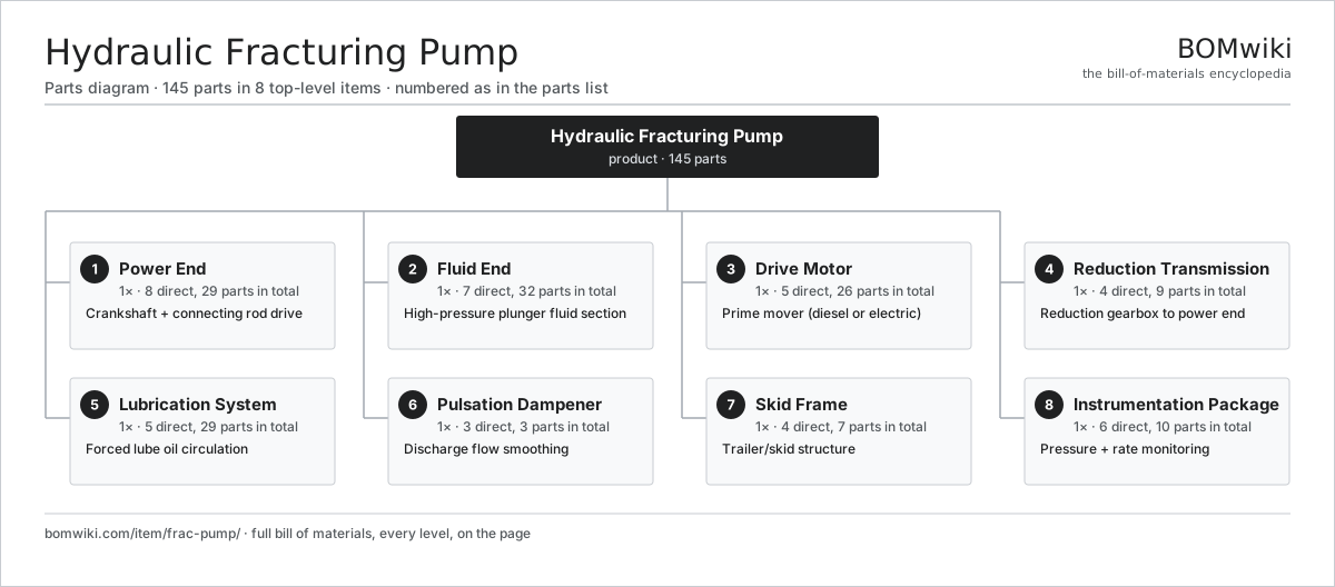
| # | Part | Qty | What it does |
|---|---|---|---|
| 1 | Power End 8 parts | 1× | Crankshaft + connecting rod drive |
| 2 | Fluid End 7 parts | 1× | High-pressure plunger fluid section |
| 3 | Drive Motor 5 parts | 1× | Prime mover (diesel or electric) |
| 4 | Reduction Transmission 4 parts | 1× | Reduction gearbox to power end |
| 5 | Lubrication System 5 parts | 1× | Forced lube oil circulation |
| 6 | Pulsation Dampener 3 parts | 1× | Discharge flow smoothing |
| 7 | Skid Frame 4 parts | 1× | Trailer/skid structure |
| 8 | Instrumentation Package 6 parts | 1× | Pressure + rate monitoring |
3D model
No 3D model yet. Have a CAD file of this? Add a 3D model. STL renders right on this page; STEP, FreeCAD, and OpenSCAD sources are welcome too (openly licensed, like all 3D models on BOMwiki).
Build & assembly graph
expand / collapse · shared sub-assemblies converge · links to related products · est. labourTap an assembly to expand/collapse · tap a part to open it · use “Open page” for any node · drag to pan, scroll to zoom.
Bill of materials for Hydraulic Fracturing Pump
8 top-level lines · 61 rows shown · 145 parts total · indented to 3 levels| # | Item / sub-assembly | Part no. | Qty/assy | Ext. qty | Parts | Type |
|---|---|---|---|---|---|---|
| 1 | Power End 8 parts | fp-power-end | 1× | 1 | 29 | assembly |
| 1.1 | Crankshaft | fp-crankshaft | 1× | 1 | · | part |
| 1.2 | Connecting Rod | fp-connecting-rod | 5× | 5 | · | part |
| 1.3 | Crosshead | fp-crosshead | 5× | 5 | · | part |
| 1.4 | Pony Rod | fp-pony-rod | 5× | 5 | · | part |
| 1.5 | Ball Bearing | ball-bearing | 6× | 6 | · | part |
| 1.6 | Gearbox Housing | gearbox-housing | 1× | 1 | · | part |
| 1.7 | Helical Gear Pair | gear-pair | 1× | 1 | · | part |
| 1.8 | Oil Seal | oil-seal | 5× | 5 | · | part |
| 2 | Fluid End 7 parts | fp-fluid-end | 1× | 1 | 32 | assembly |
| 2.1 | Fluid End Block | fp-fluid-end-block | 1× | 1 | · | part |
| 2.2 | Plunger | fp-plunger | 5× | 5 | · | part |
| 2.3 | Packing Set | fp-packing-set | 5× | 5 | · | part |
| 2.4 | Suction Valve | fp-suction-valve | 5× | 5 | · | part |
| 2.5 | Discharge Valve | fp-discharge-valve | 5× | 5 | · | part |
| 2.6 | Valve Seat | fp-valve-seat | 10× | 10 | · | part |
| 2.7 | O-Ring Set | oring-set | 1× | 1 | · | part |
| 3 | Drive Motor 5 parts | fp-drive-engine | 1× | 1 | 26 | assembly |
| 3.1 | Stator Assembly 3 parts | stator-assembly | 1× | 1 | 3 | assembly |
| 3.1.1 | Stator Core (laminations) | stator-core | 1× | 1 | · | part |
| 3.1.2 | Copper Winding | copper-winding | 1× | 1 | · | part |
| 3.1.3 | Slot Insulation | stator-insulation | 1× | 1 | · | part |
| 3.2 | Rotor Assembly 4 parts | rotor-assembly | 1× | 1 | 19 | assembly |
| 3.2.1 | Rotor Shaft | rotor-shaft | 1× | 1 | · | part |
| 3.2.2 | Rotor Core | rotor-core | 1× | 1 | · | part |
| 3.2.3 | Neodymium Magnet | neodymium-magnet | 16× | 16 | · | part |
| 3.2.4 | Ball Bearing | ball-bearing | 1× | 1 | · | part |
| 3.3 | Motor Housing | motor-housing | 1× | 1 | · | part |
| 3.4 | Ball Bearing | ball-bearing | 2× | 2 | · | part |
| 3.5 | Cooling Fan | fp-cooling-fan | 1× | 1 | · | part |
| 4 | Reduction Transmission 4 parts | fp-transmission | 1× | 1 | 9 | assembly |
| 4.1 | Helical Gear Pair | gear-pair | 2× | 2 | · | part |
| 4.2 | Gearbox Housing | gearbox-housing | 1× | 1 | · | part |
| 4.3 | Ball Bearing | ball-bearing | 4× | 4 | · | part |
| 4.4 | Oil Seal | oil-seal | 2× | 2 | · | part |
| 5 | Lubrication System 5 parts | fp-lubrication-system | 1× | 1 | 29 | assembly |
| 5.1 | Lube Oil Pump 4 parts | fp-lube-pump | 1× | 1 | 25 | assembly |
| 5.1.1 | Stator Assembly 3 parts + deeper › | stator-assembly | 1× | 1 | 3 | assembly |
| 5.1.2 | Rotor Assembly 4 parts + deeper › | rotor-assembly | 1× | 1 | 19 | assembly |
| 5.1.3 | Motor Housing | motor-housing | 1× | 1 | · | part |
| 5.1.4 | Ball Bearing | ball-bearing | 2× | 2 | · | part |
| 5.2 | Oil Cooler | fp-oil-cooler | 1× | 1 | · | part |
| 5.3 | Oil Filter | fp-oil-filter | 1× | 1 | · | part |
| 5.4 | Lube Reservoir | fp-lube-reservoir | 1× | 1 | · | part |
| 5.5 | Pressure Sensor | pressure-sensor | 1× | 1 | · | part |
| 6 | Pulsation Dampener 3 parts | fp-pulsation-dampener | 1× | 1 | 3 | assembly |
| 6.1 | Dampener Bottle | fp-dampener-bottle | 1× | 1 | · | part |
| 6.2 | Dampener Bladder | fp-dampener-bladder | 1× | 1 | · | part |
| 6.3 | O-Ring Set | oring-set | 1× | 1 | · | part |
| 7 | Skid Frame 4 parts | fp-skid-frame | 1× | 1 | 7 | assembly |
| 7.1 | Base Rails | fp-base-rails | 1× | 1 | · | part |
| 7.2 | Cross Members | fp-cross-members | 1× | 1 | · | part |
| 7.3 | Vibration Mount | fp-vibration-mount | 4× | 4 | · | part |
| 7.4 | Fastener Set | fastener-set | 1× | 1 | · | part |
| 8 | Instrumentation Package 6 parts | fp-instrumentation | 1× | 1 | 10 | assembly |
| 8.1 | Bare PCB | pcb-bare | 1× | 1 | · | part |
| 8.2 | Microcontroller | mcu | 1× | 1 | · | part |
| 8.3 | Pressure Sensor | pressure-sensor | 2× | 2 | · | part |
| 8.4 | Flow Meter | fp-flow-meter | 1× | 1 | · | part |
| 8.5 | Wire Bundle | wire-bundle | 1× | 1 | · | part |
| 8.6 | Connector | connector | 4× | 4 | · | part |
Something wrong in this list? Report a problem with this BOM.
Related products
same domain, ranked by shared parts Wireline Logging Unit
189 parts · shares 13 with this page
 Coiled Tubing Unit
190 parts · shares 12 with this page
 Drilling Top Drive
181 parts · shares 12 with this page
 Oil Pumpjack
141 parts · shares 12 with this page
Side-Entry Tank Mixer
165 parts · shares 12 with this page
Sourcing: possible vendors
Browse the supplier directory → Prices, MOQ, and lead times are algorithmic estimates, not quotes, and not claims about these companies. Company mappings are curated by keyword; est. price band $10k–$50M. How estimates work| Vendor | HQ | Specialty | MOQ | Lead time |
|---|---|---|---|---|
|
🇺🇸SLB
slb.com ↗
|
Houston, US | Oilfield services & equipment | made to order | 24–48 wks |
| halliburton.com ↗ | Houston, US | Oilfield services | made to order | 24–48 wks |
| bakerhughes.com ↗ | Houston, US | Energy technology | made to order | 24–48 wks |
|
🇺🇸NOV
nov.com ↗
|
Houston, US | Drilling equipment | made to order | 24–48 wks |
| technipfmc.com ↗ | London, GB | Subsea & surface systems | made to order | 24–48 wks |
295-word article