Drilling Mud Mixing System
ProductOverview
A drilling mud mixing system is the equipment that lets a rig crew build and maintain its drilling fluid. Drilling mud is not a fixed recipe; it is constantly adjusted while a well is drilled, with weighting material, clays, and chemicals added by the sack to change density, viscosity, and chemistry as the bit passes through different formations. This skid is where that blending happens. It pairs a Mixing Hopper that swallows dry additive with a Mixing Pump that circulates mud through it, and the whole unit sits on a Skid Frame so it can be craned onto a rig as one module.
The system reads almost like a kitchen mixer scaled up to thousands of gallons. Powder goes in the top, fluid runs through the bottom, and the two combine into a uniform slurry that returns to the mud pits. The clever part is that no mechanical agitator does the mixing inside the hopper. Instead the energy comes from the pump and a venturi, which makes the unit simple, rugged, and able to swallow the heavy abrasive barite that ordinary mixers would wear out quickly.
How it works
The mixing pump draws mud from the active pit and forces it through a Jet Nozzle aimed into the Venturi Throat under the hopper. As the high-velocity stream passes through the narrowed throat, its pressure drops sharply, and that low-pressure zone pulls dry additive down out of the Hopper Cone and into the mud. The powder is wetted and dispersed in the turbulent flow, then carried out the Discharge Line back to the pit. An operator standing on the Access Platform cuts sacks open on the Bag Breaker Grate grate and dumps the contents into the hopper as fast as the venturi can take them.
Flow routing happens at the Piping Manifold. Gate valves let the crew choose between mixing, where flow loops through the venturi, and simple transfer, where the pump just moves mud from one pit to another. A Check Valve keeps mud from draining back through the pump when it stops, and a pressure gauge on the discharge tells the operator whether the jet is making enough suction. The nozzle and throat are the wear items; the jet velocity that does the mixing also blasts metal away, so both are made of hard material and treated as consumables.
Subsystems
The Mixing Pump is a heavy-duty centrifugal pump built for solids service. Its Open Impeller uses open vanes so barite and bentonite pass through without packing the pump, and a Mechanical Seal keeps the abrasive fluid away from the Ball Bearing supports on the Pump Shaft. A Servo Motor drives it through a flexible Drive Coupling. For fluids that need full hydration, an optional High-Shear Unit adds a rotor-stator mill in the loop: the Rotor Assembly spinning close to the Stator Assembly forces the slurry through tight gaps, tearing apart polymer and clay particles so each pound of additive yields more viscosity.
Control comes from the Control Panel, an explosion-proof enclosure because the rig area carries flammable gas. Inside, an Microcontroller sequences the motor contactors, a Power Supply feeds the logic, and a small LCD Panel shows status. Interlocks stop the pump if suction is lost so it never runs dry and burns its seal.
Materials and wear
Everything in the wetted path fights abrasion. The hopper cone and throat carry a replaceable Wear Liner of polyurethane or hard iron, and the jet nozzle is tungsten carbide because it sees the fastest, most erosive flow. The pump casing and impeller are cast in hard iron rated for slurry duty. Piping is heavy-wall schedule 80 on the discharge side where pressure and erosion are highest, joined with Grooved Coupling grooved couplings so spools can be swapped quickly during rig-up and rig-down.
Variants and use
Skids are sized by pump capacity, from compact single-pump units on small workover rigs to twin-pump systems on deep land and offshore rigs that need high additive throughput. Some integrate two hoppers so one crew member can mix weighting material while another mixes chemicals. The unit serves both water-base and oil-base mud; oil-base systems add tighter sealing and spill containment in the Drip Pan because the fluid is costly and must not reach the ground. On a drilling location the mixing system works alongside the rest of the solids-control train, taking clean mud back from the pits after the shakers and centrifuges have stripped out cuttings, then re-treating it for the next interval of hole.
Drilling Mud Mixing System parts and their functions
7 top-level parts · 135 parts in total · full bill of materials below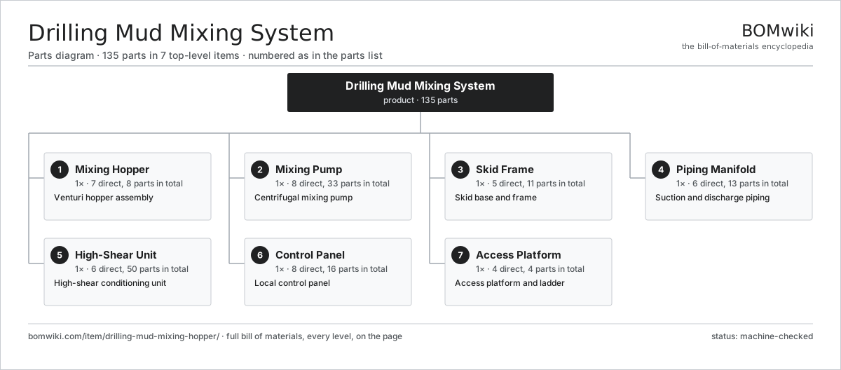
| # | Part | Qty | What it does |
|---|---|---|---|
| 1 | Mixing Hopper 7 parts | 1× | Venturi hopper assembly |
| 2 | Mixing Pump 8 parts | 1× | Centrifugal mixing pump |
| 3 | Skid Frame 5 parts | 1× | Skid base and frame |
| 4 | Piping Manifold 6 parts | 1× | Suction and discharge piping |
| 5 | High-Shear Unit 6 parts | 1× | High-shear conditioning unit |
| 6 | Control Panel 8 parts | 1× | Local control panel |
| 7 | Access Platform 4 parts | 1× | Access platform and ladder |
3D model
No 3D model yet. Have a CAD file of this? Add a 3D model. STL renders right on this page; STEP, FreeCAD, and OpenSCAD sources are welcome too (openly licensed, like all 3D models on BOMwiki).
Build & assembly graph
expand / collapse · shared sub-assemblies converge · links to related products · est. labourTap an assembly to expand/collapse · tap a part to open it · use “Open page” for any node · drag to pan, scroll to zoom.
Bill of materials for Drilling Mud Mixing System
7 top-level lines · 66 rows shown · 135 parts total · indented to 3 levels| # | Item / sub-assembly | Part no. | Qty/assy | Ext. qty | Parts | Type |
|---|---|---|---|---|---|---|
| 1 | Mixing Hopper 7 parts | dmmh-mixing-hopper | 1× | 1 | 8 | assembly |
| 1.1 | Hopper Cone | dmmh-hopper-cone | 1× | 1 | · | part |
| 1.2 | Venturi Throat | dmmh-venturi-throat | 1× | 1 | · | part |
| 1.3 | Jet Nozzle | dmmh-jet-nozzle | 1× | 1 | · | part |
| 1.4 | Butterfly Valve | dmmh-butterfly-valve | 2× | 2 | · | part |
| 1.5 | Bag Breaker Grate | dmmh-bag-breaker | 1× | 1 | · | part |
| 1.6 | Wear Liner | dmmh-wear-liner | 1× | 1 | · | part |
| 1.7 | Fastener Set | fastener-set | 1× | 1 | · | part |
| 2 | Mixing Pump 8 parts | dmmh-mixing-pump | 1× | 1 | 33 | assembly |
| 2.1 | Volute Casing | dmmh-pump-casing | 1× | 1 | · | part |
| 2.2 | Open Impeller | dmmh-pump-impeller | 1× | 1 | · | part |
| 2.3 | Mechanical Seal | dmmh-mechanical-seal | 1× | 1 | · | part |
| 2.4 | Pump Shaft | dmmh-pump-shaft | 1× | 1 | · | part |
| 2.5 | Ball Bearing | ball-bearing | 2× | 2 | · | part |
| 2.6 | Servo Motor 4 parts | servo-motor | 1× | 1 | 24 | assembly |
| 2.6.1 | Stator Assembly 3 parts + deeper › | stator-assembly | 1× | 1 | 3 | assembly |
| 2.6.2 | Rotor Assembly 4 parts + deeper › | rotor-assembly | 1× | 1 | 19 | assembly |
| 2.6.3 | Encoder | encoder | 1× | 1 | · | part |
| 2.6.4 | Motor Housing | motor-housing | 1× | 1 | · | part |
| 2.7 | Drive Coupling | dmmh-coupling | 1× | 1 | · | part |
| 2.8 | Oil Seal | oil-seal | 2× | 2 | · | part |
| 3 | Skid Frame 5 parts | dmmh-skid-frame | 1× | 1 | 11 | assembly |
| 3.1 | Base Beams | dmmh-base-beams | 1× | 1 | · | part |
| 3.2 | Lift Lug | dmmh-lift-lugs | 4× | 4 | · | part |
| 3.3 | Drip Pan | dmmh-drip-pan | 1× | 1 | · | part |
| 3.4 | Sheet Metal Panel | sheet-panel | 4× | 4 | · | part |
| 3.5 | Fastener Set | fastener-set | 1× | 1 | · | part |
| 4 | Piping Manifold 6 parts | dmmh-piping-manifold | 1× | 1 | 13 | assembly |
| 4.1 | Suction Line | dmmh-suction-line | 1× | 1 | · | part |
| 4.2 | Discharge Line | dmmh-discharge-line | 1× | 1 | · | part |
| 4.3 | Gate Valve | dmmh-gate-valve | 3× | 3 | · | part |
| 4.4 | Check Valve | dmmh-check-valve | 1× | 1 | · | part |
| 4.5 | Grooved Coupling | dmmh-victaulic-coupling | 6× | 6 | · | part |
| 4.6 | Pressure Sensor | pressure-sensor | 1× | 1 | · | part |
| 5 | High-Shear Unit 6 parts | dmmh-shear-unit | 1× | 1 | 50 | assembly |
| 5.1 | Rotor Assembly 4 parts | rotor-assembly | 1× | 1 | 19 | assembly |
| 5.1.1 | Rotor Shaft | rotor-shaft | 1× | 1 | · | part |
| 5.1.2 | Rotor Core | rotor-core | 1× | 1 | · | part |
| 5.1.3 | Neodymium Magnet | neodymium-magnet | 16× | 16 | · | part |
| 5.1.4 | Ball Bearing | ball-bearing | 1× | 1 | · | part |
| 5.2 | Stator Assembly 3 parts | stator-assembly | 1× | 1 | 3 | assembly |
| 5.2.1 | Stator Core (laminations) | stator-core | 1× | 1 | · | part |
| 5.2.2 | Copper Winding | copper-winding | 1× | 1 | · | part |
| 5.2.3 | Slot Insulation | stator-insulation | 1× | 1 | · | part |
| 5.3 | Shear Housing | dmmh-shear-housing | 1× | 1 | · | part |
| 5.4 | Ball Bearing | ball-bearing | 2× | 2 | · | part |
| 5.5 | Mechanical Seal | dmmh-mechanical-seal | 1× | 1 | · | part |
| 5.6 | Servo Motor 4 parts | servo-motor | 1× | 1 | 24 | assembly |
| 5.6.1 | Stator Assembly 3 parts + deeper › | stator-assembly | 1× | 1 | 3 | assembly |
| 5.6.2 | Rotor Assembly 4 parts + deeper › | rotor-assembly | 1× | 1 | 19 | assembly |
| 5.6.3 | Encoder | encoder | 1× | 1 | · | part |
| 5.6.4 | Motor Housing | motor-housing | 1× | 1 | · | part |
| 6 | Control Panel 8 parts | dmmh-control-panel | 1× | 1 | 16 | assembly |
| 6.1 | Explosion-Proof Enclosure | dmmh-enclosure | 1× | 1 | · | part |
| 6.2 | Bare PCB | pcb-bare | 1× | 1 | · | part |
| 6.3 | Microcontroller | mcu | 1× | 1 | · | part |
| 6.4 | Relay | relay | 4× | 4 | · | part |
| 6.5 | Power Supply | power-supply | 1× | 1 | · | part |
| 6.6 | Wire Bundle | wire-bundle | 1× | 1 | · | part |
| 6.7 | Connector | connector | 6× | 6 | · | part |
| 6.8 | LCD Panel | lcd-panel | 1× | 1 | · | part |
| 7 | Access Platform 4 parts | dmmh-walkway | 1× | 1 | 4 | assembly |
| 7.1 | Walkway Grating | dmmh-grating | 1× | 1 | · | part |
| 7.2 | Guardrail | dmmh-handrail | 1× | 1 | · | part |
| 7.3 | Access Ladder | dmmh-ladder | 1× | 1 | · | part |
| 7.4 | Fastener Set | fastener-set | 1× | 1 | · | part |
Related products
same domain, ranked by shared parts Oilwell Cementing Unit
902 parts · shares 16 with this page
Oilwell Cementing Unit
902 parts · shares 16 with this page
 Wireline Logging Unit
189 parts · shares 16 with this page
Wireline Logging Unit
189 parts · shares 16 with this page
 Gas Engine Driven Compressor
217 parts · shares 14 with this page
Gas Engine Driven Compressor
217 parts · shares 14 with this page
 Reciprocating Gas Compressor Package
187 parts · shares 14 with this page
Reciprocating Gas Compressor Package
187 parts · shares 14 with this page
 Shale Shaker
201 parts · shares 14 with this page
Shale Shaker
201 parts · shares 14 with this page
Sourcing: possible vendors
Browse the supplier directory → Prices, MOQ, and lead times are algorithmic estimates, not quotes, and not claims about these companies. Company mappings are curated by keyword; est. price band $10k–$50M. How estimates work| Vendor | HQ | Specialty | MOQ | Lead time |
|---|---|---|---|---|
|
🇺🇸SLB
slb.com ↗
|
Houston, US | Oilfield services & equipment | made to order | 24–48 wks |
| halliburton.com ↗ | Houston, US | Oilfield services | made to order | 24–48 wks |
| bakerhughes.com ↗ | Houston, US | Energy technology | made to order | 24–48 wks |
|
🇺🇸NOV
nov.com ↗
|
Houston, US | Drilling equipment | made to order | 24–48 wks |
| technipfmc.com ↗ | London, GB | Subsea & surface systems | made to order | 24–48 wks |
783-word article