Sour Water Stripper
ProductOverview
A sour water stripper removes dissolved hydrogen sulfide and ammonia from the wastewater produced across a refinery. Sour water collects from crude unit overhead drums, hydrotreater and hydrocracker separators, fluid catalytic cracking fractionators, and delayed coker fractionators. This water carries hydrogen sulfide and ammonia in equilibrium as ammonium bisulfide and ammonium sulfide, along with traces of phenols, cyanides, and entrained hydrocarbon. Discharging it untreated would poison downstream biological treatment and release toxic gas, so the stripper drives the dissolved gases back out with heat and returns clean water for reuse as desalter wash water or boiler feed makeup.
The unit is a tall distillation-style tower. Sour water enters near the top and flows down across the trays inside the Stripping Column Shell, while stripping vapor generated by the Reboiler rises up through it. The rising vapor lowers the partial pressure of the dissolved gases above each tray, pulling hydrogen sulfide and ammonia out of the liquid. Treated water leaves the bottom; a concentrated acid-gas stream leaves the top through the Overhead Condenser and goes to the sulfur recovery unit or an ammonia destruction system.
How it works
Feed first passes through the Feed Preheat System system, where the Feed Drum gives entrained oil time to skim off and the Feed/Bottoms Exchanger warms the incoming water against the hot stripped bottoms. Preheating the feed to within 30-50 F of the column top temperature recovers heat that would otherwise be spent in the reboiler. The warmed feed enters above the top tray through the Feed Distributor.
Inside the column, each Valve Tray holds a shallow pool of liquid. Vapor bubbles up through the movable valve caps and contacts the liquid, then the liquid spills over a weir and flows down the Tray Downcomer to the tray below. Stage by stage the water gives up its dissolved gas. At the base, a Chimney Collector Tray collects liquid to feed the reboiler, which boils part of it and sends the vapor back up the tower. The Vortex Breaker over the bottom outlet keeps vapor from being sucked into the Bottoms Pump.
Overhead vapor is mostly water with the stripped hydrogen sulfide and ammonia. The Overhead Condenser cools it enough to condense the water but leave the acid gas in the vapor phase. Both phases drop into the Reflux Drum, where the Mist Eliminator knocks out droplets. The Reflux Pump returns condensed water to the top of the column as reflux, which keeps ammonia from carrying overhead with the acid gas. The Pressure Control Valve holds column pressure and meters concentrated acid gas onward.
Stripping chemistry
Hydrogen sulfide and ammonia are held in the water by an acid-base equilibrium. Hydrogen sulfide is a weak acid and ammonia a weak base, and together they form ammonium bisulfide. Heating shifts the equilibrium so both gases come out of solution. A non-acidified stripper removes both gases together and sends the combined acid gas to sulfur recovery. An acidified design adds caustic or acid to split the streams, removing hydrogen sulfide first and ammonia separately, which produces a cleaner acid-gas feed for the sulfur plant. The choice depends on whether the refinery has an ammonia destruction route and on the sulfur unit's tolerance for ammonia, which can form salt plugging if not controlled.
Materials and corrosion
Ammonium bisulfide is aggressively corrosive to carbon steel above certain concentrations and velocities, so wetted surfaces are protected. The shell carries an alloy Corrosion Cladding of 316L or alloy 825 over the SA-516 base plate, and the Process Piping in the piping package is stainless. Velocity limits in the overhead and bottoms piping prevent the erosion-corrosion that ammonium bisulfide causes at high flow. The pH Analyzer in the instrument package watches bottoms alkalinity, since pH excursions accelerate attack. Heat tracing and the Steam Tracing on cold lines stop ammonium salts from crystallizing and plugging instrument taps and small-bore piping.
Instrumentation and control
The Instrument Package regulates the stripper to a residual sulfide and ammonia target. Tray and reboiler temperatures from the temperature elements set the Steam Control Valve on the reboiler so the bottoms stays hot enough to strip but not so hot that it wastes steam. The Sulfide Analyzer confirms treated water meets the discharge limit, and column pressure transmitters drive the overhead pressure control. Feed, reflux, and bottoms flow meters close the material balance, and the Control Panel hosts the controller, redundant power supply, and interposing relays.
Operation and variants
Strippers run continuously and are sized for the refinery's peak sour-water make. Capacity ranges from small single-train units of 20 gpm to large units handling 300 gpm per train, with multiple trains for redundancy. Common upsets include foaming from entrained oil or surfactants, which floods trays and degrades stripping, and ammonium salt fouling in the overhead system, which restricts flow and raises pressure. Periodic water washing of the overhead and good oil removal at the Feed Drum keep the unit stable. Treated water from the Bottoms Pump is reused where possible, closing the refinery water loop and cutting both fresh-water intake and effluent load.
Sour Water Stripper parts and their functions
9 top-level parts · 273 parts in total · full bill of materials below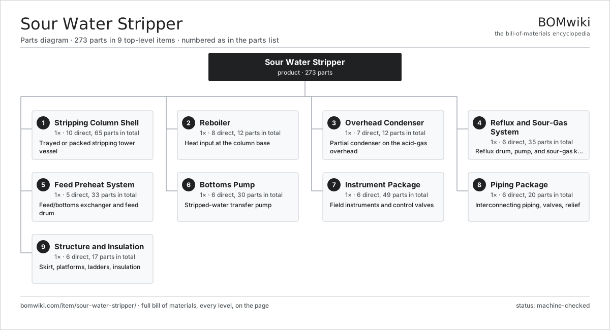
| # | Part | Qty | What it does |
|---|---|---|---|
| 1 | Stripping Column Shell 10 parts | 1× | Trayed or packed stripping tower vessel |
| 2 | Reboiler 8 parts | 1× | Heat input at the column base |
| 3 | Overhead Condenser 7 parts | 1× | Partial condenser on the acid-gas overhead |
| 4 | Reflux and Sour-Gas System 6 parts | 1× | Reflux drum, pump, and sour-gas knockout |
| 5 | Feed Preheat System 5 parts | 1× | Feed/bottoms exchanger and feed drum |
| 6 | Bottoms Pump 6 parts | 1× | Stripped-water transfer pump |
| 7 | Instrument Package 6 parts | 1× | Field instruments and control valves |
| 8 | Piping Package 6 parts | 1× | Interconnecting piping, valves, relief |
| 9 | Structure and Insulation 6 parts | 1× | Skirt, platforms, ladders, insulation |
3D model
No 3D model yet. Have a CAD file of this? Add a 3D model. STL renders right on this page; STEP, FreeCAD, and OpenSCAD sources are welcome too (openly licensed, like all 3D models on BOMwiki).
Build & assembly graph
expand / collapse · shared sub-assemblies converge · links to related products · est. labourTap an assembly to expand/collapse · tap a part to open it · use “Open page” for any node · drag to pan, scroll to zoom.
Bill of materials for Sour Water Stripper
9 top-level lines · 89 rows shown · 273 parts total · indented to 3 levels| # | Item / sub-assembly | Part no. | Qty/assy | Ext. qty | Parts | Type |
|---|---|---|---|---|---|---|
| 1 | Stripping Column Shell 10 parts | sws-column-shell | 1× | 1 | 65 | assembly |
| 1.1 | Shell Plate Course | sws-shell-course | 6× | 6 | · | part |
| 1.2 | Vessel Head | sws-head | 2× | 2 | · | part |
| 1.3 | Valve Tray | sws-valve-tray | 24× | 24 | · | part |
| 1.4 | Tray Downcomer | sws-tray-downcomer | 24× | 24 | · | part |
| 1.5 | Feed Distributor | sws-feed-distributor | 1× | 1 | · | part |
| 1.6 | Chimney Collector Tray | sws-chimney-tray | 1× | 1 | · | part |
| 1.7 | Vortex Breaker | sws-vortex-breaker | 1× | 1 | · | part |
| 1.8 | Manway | sws-manway | 4× | 4 | · | part |
| 1.9 | Nozzle Set | sws-nozzle-set | 1× | 1 | · | part |
| 1.10 | Corrosion Cladding | sws-cladding | 1× | 1 | · | part |
| 2 | Reboiler 8 parts | sws-reboiler | 1× | 1 | 12 | assembly |
| 2.1 | Reboiler Shell | sws-reboiler-shell | 1× | 1 | · | part |
| 2.2 | U-Tube Bundle | sws-reboiler-bundle | 1× | 1 | · | part |
| 2.3 | Reboiler Tubesheet | sws-reboiler-tubesheet | 1× | 1 | · | part |
| 2.4 | Steam Channel | sws-reboiler-channel | 1× | 1 | · | part |
| 2.5 | Steam Trap | sws-steam-trap | 2× | 2 | · | part |
| 2.6 | Steam Control Valve | sws-steam-control-valve | 1× | 1 | · | part |
| 2.7 | O-Ring Set | oring-set | 4× | 4 | · | part |
| 2.8 | Fastener Set | fastener-set | 1× | 1 | · | part |
| 3 | Overhead Condenser 7 parts | sws-overhead-condenser | 1× | 1 | 12 | assembly |
| 3.1 | Condenser Shell | sws-condenser-shell | 1× | 1 | · | part |
| 3.2 | Condenser Tube Bundle | sws-condenser-bundle | 1× | 1 | · | part |
| 3.3 | Condenser Tubesheet | sws-condenser-tubesheet | 2× | 2 | · | part |
| 3.4 | Water Box | sws-condenser-waterbox | 2× | 2 | · | part |
| 3.5 | Cooling-Water Control Valve | sws-cw-control-valve | 1× | 1 | · | part |
| 3.6 | O-Ring Set | oring-set | 4× | 4 | · | part |
| 3.7 | Fastener Set | fastener-set | 1× | 1 | · | part |
| 4 | Reflux and Sour-Gas System 6 parts | sws-reflux-system | 1× | 1 | 35 | assembly |
| 4.1 | Reflux Drum | sws-reflux-drum | 1× | 1 | · | part |
| 4.2 | Reflux Pump 5 parts | sws-reflux-pump | 1× | 1 | 29 | assembly |
| 4.2.1 | Pump Casing | sws-pump-casing | 1× | 1 | · | part |
| 4.2.2 | Pump Impeller | sws-pump-impeller | 1× | 1 | · | part |
| 4.2.3 | Mechanical Seal | sws-pump-mech-seal | 1× | 1 | · | part |
| 4.2.4 | Ball Bearing | ball-bearing | 2× | 2 | · | part |
| 4.2.5 | Servo Motor 4 parts + deeper › | servo-motor | 1× | 1 | 24 | assembly |
| 4.3 | Mist Eliminator | sws-mist-eliminator | 1× | 1 | · | part |
| 4.4 | Pressure Control Valve | sws-pressure-control-valve | 1× | 1 | · | part |
| 4.5 | Level Instrument | sws-level-instrument | 2× | 2 | · | part |
| 4.6 | Relief Valve | sws-relief-valve | 1× | 1 | · | part |
| 5 | Feed Preheat System 5 parts | sws-feed-preheat | 1× | 1 | 33 | assembly |
| 5.1 | Feed Drum | sws-feed-drum | 1× | 1 | · | part |
| 5.2 | Feed/Bottoms Exchanger | sws-feed-bottoms-exchanger | 1× | 1 | · | part |
| 5.3 | Feed Pump 5 parts | sws-feed-pump | 1× | 1 | 29 | assembly |
| 5.3.1 | Pump Casing | sws-pump-casing | 1× | 1 | · | part |
| 5.3.2 | Pump Impeller | sws-pump-impeller | 1× | 1 | · | part |
| 5.3.3 | Mechanical Seal | sws-pump-mech-seal | 1× | 1 | · | part |
| 5.3.4 | Ball Bearing | ball-bearing | 2× | 2 | · | part |
| 5.3.5 | Servo Motor 4 parts + deeper › | servo-motor | 1× | 1 | 24 | assembly |
| 5.4 | Feed Control Valve | sws-feed-control-valve | 1× | 1 | · | part |
| 5.5 | Oil Skimmer | sws-oil-skimmer | 1× | 1 | · | part |
| 6 | Bottoms Pump 6 parts | sws-bottoms-pump | 1× | 1 | 30 | assembly |
| 6.1 | Pump Casing | sws-pump-casing | 1× | 1 | · | part |
| 6.2 | Pump Impeller | sws-pump-impeller | 1× | 1 | · | part |
| 6.3 | Mechanical Seal | sws-pump-mech-seal | 1× | 1 | · | part |
| 6.4 | Ball Bearing | ball-bearing | 2× | 2 | · | part |
| 6.5 | Servo Motor 4 parts | servo-motor | 1× | 1 | 24 | assembly |
| 6.5.1 | Stator Assembly 3 parts + deeper › | stator-assembly | 1× | 1 | 3 | assembly |
| 6.5.2 | Rotor Assembly 4 parts + deeper › | rotor-assembly | 1× | 1 | 19 | assembly |
| 6.5.3 | Encoder | encoder | 1× | 1 | · | part |
| 6.5.4 | Motor Housing | motor-housing | 1× | 1 | · | part |
| 6.6 | Pump Baseplate | sws-pump-baseplate | 1× | 1 | · | part |
| 7 | Instrument Package 6 parts | sws-instrument-package | 1× | 1 | 49 | assembly |
| 7.1 | Pressure Sensor | pressure-sensor | 4× | 4 | · | part |
| 7.2 | Temperature Element | sws-temperature-sensor | 6× | 6 | · | part |
| 7.3 | pH Analyzer | sws-ph-analyzer | 1× | 1 | · | part |
| 7.4 | Sulfide Analyzer | sws-h2s-analyzer | 1× | 1 | · | part |
| 7.5 | Control Panel 6 parts | sws-control-panel | 1× | 1 | 34 | assembly |
| 7.5.1 | Bare PCB | pcb-bare | 2× | 2 | · | part |
| 7.5.2 | Microcontroller | mcu | 2× | 2 | · | part |
| 7.5.3 | Relay | relay | 8× | 8 | · | part |
| 7.5.4 | Power Supply | power-supply | 1× | 1 | · | part |
| 7.5.5 | Connector | connector | 20× | 20 | · | part |
| 7.5.6 | Wire Bundle | wire-bundle | 1× | 1 | · | part |
| 7.6 | Flow Meter | sws-flow-meter | 3× | 3 | · | part |
| 8 | Piping Package 6 parts | sws-piping-package | 1× | 1 | 20 | assembly |
| 8.1 | Process Piping | sws-process-piping | 1× | 1 | · | part |
| 8.2 | Isolation Valve | sws-isolation-valve | 12× | 12 | · | part |
| 8.3 | Check Valve | sws-check-valve | 4× | 4 | · | part |
| 8.4 | Relief Header | sws-relief-header | 1× | 1 | · | part |
| 8.5 | Steam Tracing | sws-steam-tracing | 1× | 1 | · | part |
| 8.6 | Fastener Set | fastener-set | 1× | 1 | · | part |
| 9 | Structure and Insulation 6 parts | sws-structure | 1× | 1 | 17 | assembly |
| 9.1 | Support Skirt | sws-skirt | 1× | 1 | · | part |
| 9.2 | Access Platform | sws-platform | 4× | 4 | · | part |
| 9.3 | Caged Ladder | sws-ladder | 2× | 2 | · | part |
| 9.4 | Thermal Insulation | sws-insulation | 1× | 1 | · | part |
| 9.5 | Sheet Metal Panel | sheet-panel | 8× | 8 | · | part |
| 9.6 | Fastener Set | fastener-set | 1× | 1 | · | part |
Related products
same domain, ranked by shared parts Amine Gas Sweetening Unit
3,543 parts · shares 14 with this page
CO2 Injection Pump
463 parts · shares 14 with this page
Amine Gas Sweetening Unit
3,543 parts · shares 14 with this page
CO2 Injection Pump
463 parts · shares 14 with this page
 Condensate Stabilizer Column
2,234 parts · shares 14 with this page
Condensate Stabilizer Column
2,234 parts · shares 14 with this page
 Delayed Coker Drum
208 parts · shares 14 with this page
Delayed Coker Drum
208 parts · shares 14 with this page
 Drilling Mud Mixing System
135 parts · shares 14 with this page
Drilling Mud Mixing System
135 parts · shares 14 with this page
 Fired Process Heater
438 parts · shares 14 with this page
Fired Process Heater
438 parts · shares 14 with this page
Sourcing: possible vendors
Browse the supplier directory → Prices, MOQ, and lead times are algorithmic estimates, not quotes, and not claims about these companies. Company mappings are curated by keyword; est. price band $10k–$50M. How estimates work| Vendor | HQ | Specialty | MOQ | Lead time |
|---|---|---|---|---|
|
🇺🇸SLB
slb.com ↗
|
Houston, US | Oilfield services & equipment | made to order | 24–48 wks |
| halliburton.com ↗ | Houston, US | Oilfield services | made to order | 24–48 wks |
| bakerhughes.com ↗ | Houston, US | Energy technology | made to order | 24–48 wks |
|
🇺🇸NOV
nov.com ↗
|
Houston, US | Drilling equipment | made to order | 24–48 wks |
| technipfmc.com ↗ | London, GB | Subsea & surface systems | made to order | 24–48 wks |
882-word article