Flare Pilot Ignition System
ProductOverview
A flare pilot ignition system keeps a refinery or plant flare continuously lit so that any gas routed to the flare is burned rather than released. The flare itself handles relief and waste gas from process units, and the pilot flames are the source that ignites that gas at the tip. If a pilot goes out, unburned hydrocarbons can vent to atmosphere, so the ignition system is treated as a safety device. It provides a reliable source of ignition, proves that each pilot is lit, and re-ignites any pilot that fails.
The system covers three jobs. It maintains continuous pilot flames at the flare tip, it detects the presence of each flame, and it re-establishes ignition on demand. A typical refinery elevated flare carries 1 to 4 pilots, with 3 being common on larger tips. Each pilot is a small burner sized for stable operation in high wind and rain. The ignition source for these pilots is most often a flame front generator located at grade, with a separate path for a high energy electric igniter where the tip geometry allows it.
Pilot burners
The pilot burners sit at the flare tip and run continuously. Each pilot uses a venturi to draw combustion air into the fuel gas by natural draft, so the venturi mixer sets the air to fuel ratio without a separate air supply at the tip. The mixed gas exits through an Inconel nozzle and is held by a flame retention cup and wind shield that make up the stabilizer. Wind speeds at an elevated tip can exceed 30 m/s, and the stabilizer geometry is what keeps the flame attached under those conditions.
Pilot fuel consumption runs from 2 to 8 Nm3/h per pilot depending on tip size and wind rating. The tip components see radiant heat from the main flare flame as well as their own combustion, so the nozzle and shroud are Inconel 625 and the mounting bracket is 310 stainless steel. Each pilot carries its own thermocouple for flame proving, mounted in the hottest part of the retention zone.
Flame front generator
The flame front generator makes a fuel and air charge, sparks it, and sends the resulting flame up a tube to the pilots. The mixing chamber receives metered fuel through one needle valve and metered air through another, so the operator can trim the mixture to a clean ignitable ratio. A spark from the spark plug, driven by an ignition coil at 10 to 20 kV, lights the charge inside the chamber. The flame then travels through the ignition line toward the tip.
The ignition line is continuous 316 stainless tubing that can run up to 120 m on a tall stack, with distribution tees splitting the front to each pilot. The flame front moves at roughly 5 to 20 m/s, so it reaches the tip within a few seconds. A check valve on the FFG blocks any flashback toward the fuel header, and a low point drain pot collects condensate that would otherwise quench the front. The combustion air for the FFG comes from the air supply, either a regenerative blower or an instrument air tie-in.
Flame detection
Reliable detection is what allows the system to re-ignite without an operator climbing the stack. The flame detection package combines several methods. Each pilot thermocouple feeds a transmitter that reports tip temperature, and a sustained drop below a setpoint flags a flameout. A ground level infrared flame scanner views the tip and confirms flame presence independently of the thermocouples. An ionization rod gives a third check on some installations. Detection signals land in a field junction box and route to the controller, with flame proving response in the 2 to 10 s range.
Pilot fuel supply
The pilot fuel gas train conditions the gas before it reaches the pilots and the FFG. A coalescing filter removes liquids and solids that would foul the nozzles, and a regulator holds pilot gas pressure at 0.3 to 2.0 barg. A restriction orifice meters the total pilot flow, and a solenoid valve gives the controller remote isolation. A pressure transmitter on the train lets the controller alarm on loss of pilot gas before the flames are lost.
Control and auto re-ignition
The ignition control panel runs the whole sequence. A PLC monitors the thermocouples and the flame scanner, and on a detected flameout it starts an automatic re-ignition cycle. That cycle opens the FFG fuel and air valves, energizes the spark through the spark driver board, and watches for flame return within a set window. Retry count and interval are configurable, and a failure to re-light after the retries raises an alarm on the HMI and the field beacon. The controller logic is similar in spirit to other embedded controllers, with the safety interlocks held in the PLC.
Materials and standards
Tip components run hot and are Inconel 625 and 310 stainless steel. The piping is 316 stainless throughout. The control enclosure and field wiring are rated for the hazardous area, typically ATEX or IECEx Zone 1 with Ex d or Ex e construction and purged enclosures where required. Flare system design follows API 537 for the flare equipment and API 521 for pressure relief and disposal, with NFPA 86 and EN 746 covering combustion safety. These standards set the pilot reliability, flame monitoring, and re-ignition requirements that the ignition system is built to meet.
Flare Pilot Ignition System parts and their functions
8 top-level parts · 149 parts in total · full bill of materials below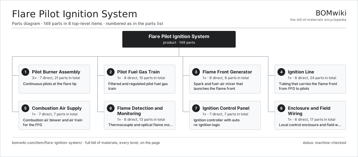
| # | Part | Qty | What it does |
|---|---|---|---|
| 1 | Pilot Burner Assembly 7 parts | 3× | Continuous pilots at the flare tip |
| 2 | Pilot Fuel Gas Train 8 parts | 1× | Filtered and regulated pilot fuel gas train |
| 3 | Flame Front Generator 8 parts | 1× | Spark and fuel-air mixer that launches the flame front |
| 4 | Ignition Line 6 parts | 1× | Tubing that carries the flame front from FFG to pilots |
| 5 | Combustion Air Supply 7 parts | 1× | Combustion air blower and air train for the FFG |
| 6 | Flame Detection and Monitoring 6 parts | 1× | Thermocouple and optical flame monitoring |
| 7 | Ignition Control Panel 7 parts | 1× | Ignition controller with auto re-ignition logic |
| 8 | Enclosure and Field Wiring 6 parts | 1× | Local control enclosure and field wiring |
3D model
No 3D model yet. Have a CAD file of this? Add a 3D model. STL renders right on this page; STEP, FreeCAD, and OpenSCAD sources are welcome too (openly licensed, like all 3D models on BOMwiki).
Build & assembly graph
expand / collapse · shared sub-assemblies converge · links to related products · est. labourTap an assembly to expand/collapse · tap a part to open it · use “Open page” for any node · drag to pan, scroll to zoom.
Bill of materials for Flare Pilot Ignition System
8 top-level lines · 63 rows shown · 149 parts total · indented to 3 levels| # | Item / sub-assembly | Part no. | Qty/assy | Ext. qty | Parts | Type |
|---|---|---|---|---|---|---|
| 1 | Pilot Burner Assembly 7 parts | flare-ignition-system-pilot-burners | 3× | 3 | 21 | assembly |
| 1.1 | Pilot Nozzle | flare-ignition-system-pilot-nozzle | 3× | 9 | · | part |
| 1.2 | Pilot Venturi Mixer | flare-ignition-system-pilot-venturi | 3× | 9 | · | part |
| 1.3 | Pilot Flame Stabilizer | flare-ignition-system-pilot-stabilizer | 3× | 9 | · | part |
| 1.4 | Pilot Thermocouple | flare-ignition-system-pilot-thermocouple | 3× | 9 | · | part |
| 1.5 | Pilot Tip Shroud | flare-ignition-system-pilot-tip-shroud | 3× | 9 | · | part |
| 1.6 | Pilot Mount Bracket | flare-ignition-system-pilot-mount-bracket | 3× | 9 | · | part |
| 1.7 | Fastener Set | fastener-set | 3× | 9 | · | part |
| 2 | Pilot Fuel Gas Train 8 parts | flare-ignition-system-pilot-fuel-gas | 1× | 1 | 10 | assembly |
| 2.1 | Fuel Gas Filter | flare-ignition-system-fuel-filter | 1× | 1 | · | part |
| 2.2 | Fuel Gas Regulator | flare-ignition-system-fuel-regulator | 1× | 1 | · | part |
| 2.3 | Fuel Shutoff Valve | flare-ignition-system-fuel-shutoff-valve | 2× | 2 | · | part |
| 2.4 | Fuel Solenoid Valve | flare-ignition-system-fuel-solenoid-valve | 1× | 1 | · | part |
| 2.5 | Pilot Flow Orifice | flare-ignition-system-fuel-flow-orifice | 1× | 1 | · | part |
| 2.6 | Fuel Pressure Gauge | flare-ignition-system-fuel-pressure-gauge | 2× | 2 | · | part |
| 2.7 | Pilot Fuel Tubing | flare-ignition-system-fuel-tubing | 1× | 1 | · | part |
| 2.8 | Pressure Sensor | pressure-sensor | 1× | 1 | · | part |
| 3 | Flame Front Generator 8 parts | flare-ignition-system-flame-front-generator | 1× | 1 | 8 | assembly |
| 3.1 | FFG Mixing Chamber | flare-ignition-system-ffg-mixing-chamber | 1× | 1 | · | part |
| 3.2 | FFG Spark Plug | flare-ignition-system-ffg-spark-plug | 1× | 1 | · | part |
| 3.3 | FFG Ignition Coil | flare-ignition-system-ffg-ignition-coil | 1× | 1 | · | part |
| 3.4 | FFG Fuel Needle Valve | flare-ignition-system-ffg-fuel-needle-valve | 1× | 1 | · | part |
| 3.5 | FFG Air Needle Valve | flare-ignition-system-ffg-air-needle-valve | 1× | 1 | · | part |
| 3.6 | FFG Check Valve | flare-ignition-system-ffg-check-valve | 1× | 1 | · | part |
| 3.7 | FFG Sight Port | flare-ignition-system-ffg-sight-port | 1× | 1 | · | part |
| 3.8 | Fastener Set | fastener-set | 1× | 1 | · | part |
| 4 | Ignition Line 6 parts | flare-ignition-system-ignition-line | 1× | 1 | 24 | assembly |
| 4.1 | Ignition Tubing | flare-ignition-system-ignition-tubing | 1× | 1 | · | part |
| 4.2 | Ignition Distribution Tee | flare-ignition-system-ignition-tee | 3× | 3 | · | part |
| 4.3 | Ignition Line Elbow | flare-ignition-system-ignition-elbow | 6× | 6 | · | part |
| 4.4 | Ignition Pipe Clamp | flare-ignition-system-ignition-pipe-clamp | 12× | 12 | · | part |
| 4.5 | Ignition Line Drain Pot | flare-ignition-system-ignition-drain-pot | 1× | 1 | · | part |
| 4.6 | Fastener Set | fastener-set | 1× | 1 | · | part |
| 5 | Combustion Air Supply 7 parts | flare-ignition-system-air-supply | 1× | 1 | 7 | assembly |
| 5.1 | Combustion Air Blower | flare-ignition-system-air-blower | 1× | 1 | · | part |
| 5.2 | Blower Motor | flare-ignition-system-air-blower-motor | 1× | 1 | · | part |
| 5.3 | Air Inlet Filter | flare-ignition-system-air-filter | 1× | 1 | · | part |
| 5.4 | Air Check Valve | flare-ignition-system-air-check-valve | 1× | 1 | · | part |
| 5.5 | Air Pressure Regulator | flare-ignition-system-air-regulator | 1× | 1 | · | part |
| 5.6 | Air Supply Tubing | flare-ignition-system-air-tubing | 1× | 1 | · | part |
| 5.7 | Pressure Sensor | pressure-sensor | 1× | 1 | · | part |
| 6 | Flame Detection and Monitoring 6 parts | flare-ignition-system-flame-detection | 1× | 1 | 13 | assembly |
| 6.1 | Thermocouple Transmitter | flare-ignition-system-thermocouple-transmitter | 3× | 3 | · | part |
| 6.2 | IR Flame Scanner | flare-ignition-system-ir-flame-scanner | 1× | 1 | · | part |
| 6.3 | Ionization Rod | flare-ignition-system-ionization-rod | 1× | 1 | · | part |
| 6.4 | Detection Junction Box | flare-ignition-system-detection-junction-box | 1× | 1 | · | part |
| 6.5 | Thermocouple Extension Cable | flare-ignition-system-thermocouple-ext-cable | 3× | 3 | · | part |
| 6.6 | Connector | connector | 4× | 4 | · | part |
| 7 | Ignition Control Panel 7 parts | flare-ignition-system-control-panel | 1× | 1 | 7 | assembly |
| 7.1 | PLC Module | flare-ignition-system-plc-module | 1× | 1 | · | part |
| 7.2 | Controller I/O Board | flare-ignition-system-controller-board | 1× | 1 | · | part |
| 7.3 | HMI Operator Panel | flare-ignition-system-hmi-panel | 1× | 1 | · | part |
| 7.4 | Spark Driver Board | flare-ignition-system-spark-driver-board | 1× | 1 | · | part |
| 7.5 | Control Power Supply | flare-ignition-system-control-power-supply | 1× | 1 | · | part |
| 7.6 | Output Relay Bank | flare-ignition-system-relay-bank | 1× | 1 | · | part |
| 7.7 | Alarm Beacon and Horn | flare-ignition-system-alarm-beacon | 1× | 1 | · | part |
| 8 | Enclosure and Field Wiring 6 parts | flare-ignition-system-enclosure-wiring | 1× | 1 | 17 | assembly |
| 8.1 | Control Enclosure | flare-ignition-system-control-enclosure | 1× | 1 | · | part |
| 8.2 | Terminal Blocks | flare-ignition-system-terminal-blocks | 1× | 1 | · | part |
| 8.3 | Cable Glands | flare-ignition-system-cable-glands | 12× | 12 | · | part |
| 8.4 | Field Conduit | flare-ignition-system-field-conduit | 1× | 1 | · | part |
| 8.5 | Enclosure Purge Fitting | flare-ignition-system-purge-fitting | 1× | 1 | · | part |
| 8.6 | Wire Bundle | wire-bundle | 1× | 1 | · | part |
Sourcing: possible vendors
Browse the supplier directory → Prices, MOQ, and lead times are algorithmic estimates, not quotes, and not claims about these companies. Company mappings are curated by keyword; est. price band $10k–$50M. How estimates work| Vendor | HQ | Specialty | MOQ | Lead time |
|---|---|---|---|---|
|
🇺🇸SLB
slb.com ↗
|
Houston, US | Oilfield services & equipment | made to order | 24–48 wks |
| halliburton.com ↗ | Houston, US | Oilfield services | made to order | 24–48 wks |
| bakerhughes.com ↗ | Houston, US | Energy technology | made to order | 24–48 wks |
|
🇺🇸NOV
nov.com ↗
|
Houston, US | Drilling equipment | made to order | 24–48 wks |
| technipfmc.com ↗ | London, GB | Subsea & surface systems | made to order | 24–48 wks |
1,004-word article