Flare Knockout Drum
ProductOverview
A flare knockout drum is a large pressure vessel sitting between the plant flare header and the flare stack. Its job is to remove and store liquids that travel with relief and blowdown gas so that only vapor reaches the flare tip. When a process unit relieves through its pressure safety valves, the released stream often carries condensate, heavy hydrocarbons, and entrained water. If that liquid reaches the burning flare tip, it falls as flaming droplets, a hazard called burning rain or liquid fallout that can ignite ground equipment and injure personnel. The knockout drum prevents this by slowing the gas, dropping out the liquid, and holding it until pumps remove it.
The unit described here is a horizontal vessel with an inside diameter of 2.5 to 4.5 m and a tangent-to-tangent length of 8 to 15 m. Horizontal geometry gives a long, low-velocity gas path and a wide liquid surface, both of which favor separation. The vessel is built to ASME VIII Division 1, sized per Pressure Vessel Shell, and the overall flare system follows API 521 for relief loads and API 537 for flare equipment.
Separation principle
Separation works in two stages. The first stage is momentum and gravity. Relief gas enters through a large flanged nozzle and strikes the Inlet Diverter Assembly, a half-pipe diverter backed by an impingement plate. The diverter breaks the high-velocity inlet jet, drops bulk liquid straight down, and spreads the remaining gas across the vessel cross section. Once the gas is moving slowly along the length of the drum, gravity pulls droplets down toward the liquid pool. A horizontal drum is sized so that the vapor velocity stays low enough that droplets of 300 to 600 micron settle out before the gas reaches the outlet.
The second stage handles the fine mist that gravity alone cannot catch. Smaller droplets follow the gas and would otherwise leave through the vapor outlet, so the design relies on the Mist Eliminator to coalesce and drop them.
Vessel design
The shell is rolled from SA-516 Gr 70 carbon-steel plate in several courses, closed at each end with 2:1 elliptical heads. A corrosion allowance of 3.0 mm is standard, increased to 6 mm where the relief stream contains hydrogen sulfide or water. Design pressure is modest, around 3.5 barg, because the flare header itself operates near atmospheric pressure and the drum mainly sees pressure during a relief event. Design temperature spans -29 °C to 250 °C to cover both cold blowdown and hot relief cases.
Process connections, the vapor outlet, and the access opening are grouped in Nozzles and Manway. The 24 inch manway lets crews enter for inspection and demister cleaning. Because the vessel is large and runs near ambient pressure, it rests on two welded saddles described in Vessel Supports. One saddle is fixed and the other carries a sliding plate so the shell can grow and shrink with temperature without straining the foundation.
Mist elimination
The mist eliminator is a 316L stainless vane pack, often with a knitted wire mesh pad acting as a pre-coalescer. Gas weaves through the chevron vanes, and inertia throws droplets against the vane walls where they merge into a film. The film runs down drain channels and falls back into the liquid pool rather than re-entraining. A vane pack pulls the carryover droplet size down toward 10 micron, far finer than gravity settling alone, which is what keeps the flare tip free of liquid. Hold-down bars restrain the pack against the lift of the rising gas.
Liquid handling
Separated liquid collects in the Liquid Collection Boot, a sump welded to the underside of the shell. The boot adds working volume, 15 to 60 m3 depending on the relief duty, so the drum can absorb a slug of liquid during a large upset without flooding. A vortex breaker over the drain stops gas from being pulled into the pump suction as the level falls.
Level is watched by Level Instrumentation and Control, which combines guided-wave radar transmitters, float switches, a local magnetic gauge, and an independent high-level alarm. On rising level the controls start the Condensate Pumpout System, a skid with duty and standby condensate pumps that send the liquid to a slop or recovery system. Pump shafts run on shared leaf components such as Ball Bearing and Oil Seal. Vessel pressure is read by a Pressure Sensor feeding the same control loop, and a high-level trip protects against carryover if the pumps cannot keep up.
Materials and codes
Carbon steel suits most flare service, with stainless internals where chlorides or sour gas attack the demister. The vessel carries an ASME U-stamp, and relief sizing follows API 521, which sets the governing relief load from fire, blocked outlet, and other contingency cases. API 537 covers the flare equipment downstream. Welds are radiographed and the completed drum is hydrostatically tested before commissioning.
Operation and applications
Flare knockout drums serve refineries, gas plants, petrochemical units, and offshore platforms wherever a relief system must burn vapor safely. In cold climates the Steam Heating Coil, an internal steam coil, keeps collected liquid above its pour point so it stays pumpable and the drains do not freeze. Routine operation is passive: the drum sits in standby, holding only the small liquid load from continuous purge and minor leaks, then accepts and separates a large transient load during an upset. Periodic inspection checks the demister for fouling, the boot for solids, and the shell for corrosion against the design allowance.
Flare Knockout Drum parts and their functions
9 top-level parts · 97 parts in total · full bill of materials below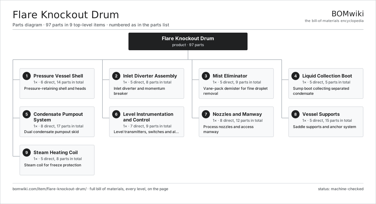
| # | Part | Qty | What it does |
|---|---|---|---|
| 1 | Pressure Vessel Shell 6 parts | 1× | Pressure-retaining shell and heads |
| 2 | Inlet Diverter Assembly 5 parts | 1× | Inlet diverter and momentum breaker |
| 3 | Mist Eliminator 5 parts | 1× | Vane-pack demister for fine droplet removal |
| 4 | Liquid Collection Boot 5 parts | 1× | Sump boot collecting separated condensate |
| 5 | Condensate Pumpout System 8 parts | 1× | Dual condensate pumpout skid |
| 6 | Level Instrumentation and Control 7 parts | 1× | Level transmitters, switches and alarm logic |
| 7 | Nozzles and Manway 8 parts | 1× | Process nozzles and access manway |
| 8 | Vessel Supports 5 parts | 1× | Saddle supports and anchor system |
| 9 | Steam Heating Coil 5 parts | 1× | Steam coil for freeze protection |
3D model
No 3D model yet. Have a CAD file of this? Add a 3D model. STL renders right on this page; STEP, FreeCAD, and OpenSCAD sources are welcome too (openly licensed, like all 3D models on BOMwiki).
Build & assembly graph
expand / collapse · shared sub-assemblies converge · links to related products · est. labourTap an assembly to expand/collapse · tap a part to open it · use “Open page” for any node · drag to pan, scroll to zoom.
Bill of materials for Flare Knockout Drum
9 top-level lines · 63 rows shown · 97 parts total · indented to 3 levels| # | Item / sub-assembly | Part no. | Qty/assy | Ext. qty | Parts | Type |
|---|---|---|---|---|---|---|
| 1 | Pressure Vessel Shell 6 parts | flare-knockout-drum-vessel-shell | 1× | 1 | 14 | assembly |
| 1.1 | Shell Course | flare-knockout-drum-shell-course | 3× | 3 | · | part |
| 1.2 | Dished Head | flare-knockout-drum-head | 2× | 2 | · | part |
| 1.3 | Corrosion Allowance Overlay | flare-knockout-drum-corrosion-liner | 1× | 1 | · | part |
| 1.4 | Circumferential Weld Seam | flare-knockout-drum-circ-weld-seam | 4× | 4 | · | part |
| 1.5 | Longitudinal Weld Seam | flare-knockout-drum-long-weld-seam | 3× | 3 | · | part |
| 1.6 | ASME Nameplate | flare-knockout-drum-nameplate | 1× | 1 | · | part |
| 2 | Inlet Diverter Assembly 5 parts | flare-knockout-drum-inlet-device | 1× | 1 | 8 | assembly |
| 2.1 | Inlet Nozzle | flare-knockout-drum-inlet-nozzle | 1× | 1 | · | part |
| 2.2 | Half-Pipe Diverter | flare-knockout-drum-half-pipe-diverter | 1× | 1 | · | part |
| 2.3 | Impingement Plate | flare-knockout-drum-impingement-plate | 1× | 1 | · | part |
| 2.4 | Diverter Bracket | flare-knockout-drum-diverter-bracket | 4× | 4 | · | part |
| 2.5 | Fastener Set | fastener-set | 1× | 1 | · | part |
| 3 | Mist Eliminator 5 parts | flare-knockout-drum-mist-eliminator | 1× | 1 | 9 | assembly |
| 3.1 | Vane Pack | flare-knockout-drum-vane-pack | 1× | 1 | · | part |
| 3.2 | Mesh Coalescer Pad | flare-knockout-drum-mesh-pad | 1× | 1 | · | part |
| 3.3 | Demister Support Grid | flare-knockout-drum-demister-grid | 1× | 1 | · | part |
| 3.4 | Drain Channel | flare-knockout-drum-drain-channel | 2× | 2 | · | part |
| 3.5 | Hold-Down Bar | flare-knockout-drum-hold-down-bar | 4× | 4 | · | part |
| 4 | Liquid Collection Boot 5 parts | flare-knockout-drum-liquid-boot | 1× | 1 | 5 | assembly |
| 4.1 | Boot Shell | flare-knockout-drum-boot-shell | 1× | 1 | · | part |
| 4.2 | Boot Head | flare-knockout-drum-boot-head | 1× | 1 | · | part |
| 4.3 | Vortex Breaker | flare-knockout-drum-vortex-breaker | 1× | 1 | · | part |
| 4.4 | Drain Nozzle | flare-knockout-drum-drain-nozzle | 1× | 1 | · | part |
| 4.5 | Sump Screen | flare-knockout-drum-sump-screen | 1× | 1 | · | part |
| 5 | Condensate Pumpout System 8 parts | flare-knockout-drum-pumpout-system | 1× | 1 | 17 | assembly |
| 5.1 | Condensate Pump | flare-knockout-drum-condensate-pump | 2× | 2 | · | part |
| 5.2 | Pump Motor | flare-knockout-drum-pump-motor | 2× | 2 | · | part |
| 5.3 | Discharge Valve | flare-knockout-drum-discharge-valve | 2× | 2 | · | part |
| 5.4 | Check Valve | flare-knockout-drum-check-valve | 2× | 2 | · | part |
| 5.5 | Suction Strainer | flare-knockout-drum-strainer | 2× | 2 | · | part |
| 5.6 | Pump Skid | flare-knockout-drum-pump-skid | 1× | 1 | · | part |
| 5.7 | Ball Bearing | ball-bearing | 4× | 4 | · | part |
| 5.8 | Oil Seal | oil-seal | 2× | 2 | · | part |
| 6 | Level Instrumentation and Control 7 parts | flare-knockout-drum-level-control | 1× | 1 | 9 | assembly |
| 6.1 | Level Transmitter | flare-knockout-drum-level-transmitter | 2× | 2 | · | part |
| 6.2 | Level Switch | flare-knockout-drum-level-switch | 2× | 2 | · | part |
| 6.3 | Magnetic Level Gauge | flare-knockout-drum-level-gauge | 1× | 1 | · | part |
| 6.4 | High-Level Alarm | flare-knockout-drum-high-level-alarm | 1× | 1 | · | part |
| 6.5 | Junction Box | flare-knockout-drum-junction-box | 1× | 1 | · | part |
| 6.6 | Pressure Sensor | pressure-sensor | 1× | 1 | · | part |
| 6.7 | Wire Bundle | wire-bundle | 1× | 1 | · | part |
| 7 | Nozzles and Manway 8 parts | flare-knockout-drum-nozzles-manway | 1× | 1 | 12 | assembly |
| 7.1 | Vapor Outlet Nozzle | flare-knockout-drum-vapor-outlet-nozzle | 1× | 1 | · | part |
| 7.2 | Relief Connection | flare-knockout-drum-relief-connection | 1× | 1 | · | part |
| 7.3 | Manway | flare-knockout-drum-manway | 1× | 1 | · | part |
| 7.4 | Manway Cover | flare-knockout-drum-manway-cover | 1× | 1 | · | part |
| 7.5 | Instrument Nozzle | flare-knockout-drum-instrument-nozzle | 4× | 4 | · | part |
| 7.6 | Nozzle Flange Set | flare-knockout-drum-flange-set | 1× | 1 | · | part |
| 7.7 | O-Ring Set | oring-set | 1× | 1 | · | part |
| 7.8 | Fastener Set | fastener-set | 2× | 2 | · | part |
| 8 | Vessel Supports 5 parts | flare-knockout-drum-supports | 1× | 1 | 15 | assembly |
| 8.1 | Saddle Support | flare-knockout-drum-saddle | 2× | 2 | · | part |
| 8.2 | Saddle Wear Plate | flare-knockout-drum-wear-plate | 2× | 2 | · | part |
| 8.3 | Anchor Bolt | flare-knockout-drum-anchor-bolt | 8× | 8 | · | part |
| 8.4 | Sliding Plate | flare-knockout-drum-sliding-plate | 1× | 1 | · | part |
| 8.5 | Earthing Lug | flare-knockout-drum-earthing-lug | 2× | 2 | · | part |
| 9 | Steam Heating Coil 5 parts | flare-knockout-drum-heating-coil | 1× | 1 | 8 | assembly |
| 9.1 | Coil Tube Bundle | flare-knockout-drum-coil-tube | 1× | 1 | · | part |
| 9.2 | Coil Inlet Nozzle | flare-knockout-drum-coil-inlet-nozzle | 1× | 1 | · | part |
| 9.3 | Coil Outlet Nozzle | flare-knockout-drum-coil-outlet-nozzle | 1× | 1 | · | part |
| 9.4 | Coil Support | flare-knockout-drum-coil-support | 4× | 4 | · | part |
| 9.5 | Steam Trap | flare-knockout-drum-steam-trap | 1× | 1 | · | part |
Related products
same domain, ranked by shared parts Deepwater Drillship
891,301 parts · shares 2 with this page
Deepwater Drillship
891,301 parts · shares 2 with this page
 Drilling Mud Degasser
154 parts · shares 2 with this page
Drilling Mud Degasser
154 parts · shares 2 with this page
 Drilling Mud Mixing System
135 parts · shares 2 with this page
Drilling Mud Mixing System
135 parts · shares 2 with this page
 Drilling Top Drive
181 parts · shares 2 with this page
Electric Submersible Pump (ESP)
635 parts · shares 2 with this page
Drilling Top Drive
181 parts · shares 2 with this page
Electric Submersible Pump (ESP)
635 parts · shares 2 with this page
Sourcing: possible vendors
Browse the supplier directory → Prices, MOQ, and lead times are algorithmic estimates, not quotes, and not claims about these companies. Company mappings are curated by keyword; est. price band $10k–$50M. How estimates work| Vendor | HQ | Specialty | MOQ | Lead time |
|---|---|---|---|---|
|
🇺🇸SLB
slb.com ↗
|
Houston, US | Oilfield services & equipment | made to order | 24–48 wks |
| halliburton.com ↗ | Houston, US | Oilfield services | made to order | 24–48 wks |
| bakerhughes.com ↗ | Houston, US | Energy technology | made to order | 24–48 wks |
|
🇺🇸NOV
nov.com ↗
|
Houston, US | Drilling equipment | made to order | 24–48 wks |
| technipfmc.com ↗ | London, GB | Subsea & surface systems | made to order | 24–48 wks |
952-word article