Plunger Lift System
ProductOverview
A gas well that produces water or condensate suffers from liquid loading: as reservoir pressure declines the gas velocity in the tubing drops below the rate needed to carry liquid to surface, so liquid falls back, collects in the bore, and the hydrostatic head it adds chokes off gas flow until the well stops on its own. A Plunger Lift System addresses this without rods, downhole motors, or injected gas. It uses a free piston, the Plunger, that travels the full length of the tubing on a cycle timed by a surface Plunger Lift Controller. On each cycle the plunger falls to the bottom of the well, a slug of liquid accumulates above it, the controller shuts the well in to let casing pressure build, then opens the Motor Valve Assembly so the stored pressure drives the plunger and the liquid slug up to surface. Plunger lift is the lowest-cost artificial lift method for many gas wells because the energy comes from the well itself.
The plunger and its types
The Plunger is a steel piston sized to the tubing drift diameter. Its job is to form a solid moving interface between the gas pushing from below and the liquid riding on top, so it minimizes the fallback of liquid past the piston. The body is the Plunger Mandrel, a hardened steel core that carries the wear surfaces and houses any internal valve. The sealing element, the Sealing Pads, is what distinguishes the main plunger families. A solid plunger has fixed turbulent-seal grooves or expanding pads and is simple and rugged but must free-fall through gas only, which forces a long shut-in to let it reach bottom. A bypass plunger carries an internal Bypass Valve Internals and a dart held open by the Internal Clutch and Dart Spring: on the way down gas passes straight through the body so the plunger falls fast even through standing liquid, then the dart trips shut when the plunger strikes the bumper spring, which shortens cycle time and suits higher-rate wells. Brush and pad plungers trade some seal efficiency for tolerance of solids, paraffin, and deviated tubing. Every plunger carries a Fishing Neck so a slickline crew can pull it for inspection without killing the well, and internal O-Ring Set seals keep the bypass mechanism clean.
The bottom hole bumper spring
Near the bottom of the tubing the Bottom Hole Bumper Spring Assembly gives the plunger a defined surface to land on. Without it a falling plunger would slam the tubing or fall into liquid and never reset. The assembly anchors on a Collar Stop / Tubing Stop that slip-sets in the tubing or lands in a Seating Nipple run as part of the string. A Coil Spring carried on the Spring Rod cushions the impact, and on a bypass plunger that same impact trips the dart closed so the plunger is ready to be lifted. Setting depth matters: the stop is placed below the perforations or at the deepest practical point so the plunger sweeps the maximum column of liquid on each rise. A Fastener Set of slips and lock screws holds the stop against the lifting load.
The surface lubricator and catcher
At surface the plunger arrives at speed and must be stopped safely. The Lubricator and Catcher Assembly is a heavy-wall housing, the Lubricator Body, mounted above the master valve and rated to wellhead pressure. The arriving plunger hits the Striker Pad, a replaceable cushion that absorbs the impact and saves the body and the Top Cap from wear. The Plunger Catcher Mechanism latches the plunger at surface so an operator, or the controller, can release it on a controlled fall instead of letting it drop the instant the well shuts in. An Arrival Sensor, a magnetic or acoustic switch, tells the controller the exact moment the plunger reaches surface, which is the single most useful input for tuning the cycle. Body and cap seals come from the O-Ring Set, and the cap and flange are made up with a Fastener Set. Produced fluid leaves the lubricator into the flowline below the catcher.
The motor valve and controller
The Motor Valve Assembly is the on/off valve in the sales flowline that starts and stops production. Its Motor Valve Body passes full well rate, a diaphragm Diaphragm Actuator strokes it on supply gas, and the Pneumatic Pilot Relay converts the controller signal into that gas command. A Coil Spring returns the actuator to a fail-safe position if it loses air. The brain is the Plunger Lift Controller, built around an Microcontroller that runs the cycle logic. It reads the Sensor Package, which carries separate Pressure Sensor transducers for casing, tubing, and line pressure on a Sensor Manifold, plus the arrival contact. The controller runs off a Solar Panel charging a Backup Battery through a Power Supply regulator, and a RTU / Telemetry Radio reports cycle counts and alarms to SCADA. Field wiring uses a Wire Bundle and weatherproof Connector terminations inside the Controller Enclosure.
The operating cycle
A plunger lift cycle has four phases. In shut-in the Motor Valve Assembly is closed, the plunger sits at the bumper spring, and casing pressure builds as gas accumulates in the annulus. When the controller decides enough pressure has stored, by elapsed time, by casing setpoint, or by a load factor computed from the three pressures, it opens the valve. In the rise phase the casing pressure expands into the tubing below the plunger and drives the plunger and the liquid slug to surface; the plunger should arrive within a target travel time, neither too fast, which wastes gas, nor too slow, which risks the plunger stalling in the tubing. Arrival is confirmed by the Arrival Sensor. In afterflow the well produces gas freely through the open valve while the plunger is held in the Lubricator and Catcher Assembly, drawing the well down until flow weakens. The controller then shuts in, releases the plunger from the Plunger Catcher Mechanism, and the cycle repeats.
Applications and optimization
Plunger lift fits gas wells with enough reservoir pressure to lift the liquid but not enough velocity to keep the bore clean, which describes a large share of mature tight-gas and coalbed wells. Tuning is iterative: the operator adjusts shut-in time, afterflow time, and the pressure setpoints from the cycle data the Plunger Lift Controller logs, watching plunger arrival times and liquid recovery. Too short a shut-in starves the rise and the plunger stalls; too long a shut-in throws away producible gas. Smart controllers close the loop on arrival velocity and casing build-up rate automatically. When a well declines past what plunger lift can carry it is often paired with a compressor or converted to gas-assisted plunger lift, where injected gas supplements the reservoir energy that drives the Plunger.
Plunger Lift System parts and their functions
7 top-level parts · 47 parts in total · full bill of materials below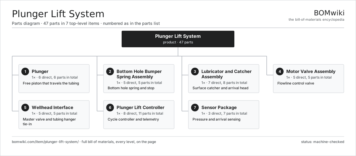
| # | Part | Qty | What it does |
|---|---|---|---|
| 1 | Plunger 6 parts | 1× | Free piston that travels the tubing |
| 2 | Bottom Hole Bumper Spring Assembly 5 parts | 1× | Bottom hole spring and stop |
| 3 | Lubricator and Catcher Assembly 7 parts | 1× | Surface catcher and arrival head |
| 4 | Motor Valve Assembly 5 parts | 1× | Flowline control valve |
| 5 | Wellhead Interface 5 parts | 1× | Master valve and tubing hanger tie-in |
| 6 | Plunger Lift Controller 8 parts | 1× | Cycle controller and telemetry |
| 7 | Sensor Package 3 parts | 1× | Pressure and arrival sensing |
3D model
No 3D model yet. Have a CAD file of this? Add a 3D model. STL renders right on this page; STEP, FreeCAD, and OpenSCAD sources are welcome too (openly licensed, like all 3D models on BOMwiki).
Build & assembly graph
expand / collapse · shared sub-assemblies converge · links to related products · est. labourTap an assembly to expand/collapse · tap a part to open it · use “Open page” for any node · drag to pan, scroll to zoom.
Bill of materials for Plunger Lift System
7 top-level lines · 46 rows shown · 47 parts total · indented to 3 levels| # | Item / sub-assembly | Part no. | Qty/assy | Ext. qty | Parts | Type |
|---|---|---|---|---|---|---|
| 1 | Plunger 6 parts | pls-plunger | 1× | 1 | 6 | assembly |
| 1.1 | Plunger Mandrel | pls-mandrel | 1× | 1 | · | part |
| 1.2 | Sealing Pads | pls-seal-pads | 1× | 1 | · | part |
| 1.3 | Bypass Valve Internals | pls-bypass-valve | 1× | 1 | · | part |
| 1.4 | Fishing Neck | pls-fishing-neck | 1× | 1 | · | part |
| 1.5 | Internal Clutch and Dart Spring | pls-spring-clutch | 1× | 1 | · | part |
| 1.6 | O-Ring Set | oring-set | 1× | 1 | · | part |
| 2 | Bottom Hole Bumper Spring Assembly 5 parts | pls-bumper-spring-assy | 1× | 1 | 5 | assembly |
| 2.1 | Coil Spring | coil-spring | 1× | 1 | · | part |
| 2.2 | Collar Stop / Tubing Stop | pls-collar-stop | 1× | 1 | · | part |
| 2.3 | Seating Nipple | pls-seating-nipple | 1× | 1 | · | part |
| 2.4 | Spring Rod | pls-spring-rod | 1× | 1 | · | part |
| 2.5 | Fastener Set | fastener-set | 1× | 1 | · | part |
| 3 | Lubricator and Catcher Assembly 7 parts | pls-lubricator-assy | 1× | 1 | 8 | assembly |
| 3.1 | Lubricator Body | pls-lubricator-body | 1× | 1 | · | part |
| 3.2 | Plunger Catcher Mechanism | pls-plunger-catcher | 1× | 1 | · | part |
| 3.3 | Arrival Sensor | pls-arrival-sensor | 1× | 1 | · | part |
| 3.4 | Top Cap | pls-top-cap | 1× | 1 | · | part |
| 3.5 | Striker Pad | pls-striker-pad | 1× | 1 | · | part |
| 3.6 | O-Ring Set | oring-set | 2× | 2 | · | part |
| 3.7 | Fastener Set | fastener-set | 1× | 1 | · | part |
| 4 | Motor Valve Assembly 5 parts | pls-motor-valve-assy | 1× | 1 | 5 | assembly |
| 4.1 | Motor Valve Body | pls-valve-body | 1× | 1 | · | part |
| 4.2 | Diaphragm Actuator | pls-valve-actuator | 1× | 1 | · | part |
| 4.3 | Pneumatic Pilot Relay | pls-valve-pilot | 1× | 1 | · | part |
| 4.4 | Coil Spring | coil-spring | 1× | 1 | · | part |
| 4.5 | O-Ring Set | oring-set | 1× | 1 | · | part |
| 5 | Wellhead Interface 5 parts | pls-wellhead-interface | 1× | 1 | 5 | assembly |
| 5.1 | Master Valve | pls-master-valve | 1× | 1 | · | part |
| 5.2 | Tubing Hanger | pls-tubing-hanger | 1× | 1 | · | part |
| 5.3 | Flange Adapter Spool | pls-flange-spool | 1× | 1 | · | part |
| 5.4 | O-Ring Set | oring-set | 1× | 1 | · | part |
| 5.5 | Fastener Set | fastener-set | 1× | 1 | · | part |
| 6 | Plunger Lift Controller 8 parts | pls-controller-assy | 1× | 1 | 11 | assembly |
| 6.1 | Microcontroller | mcu | 1× | 1 | · | part |
| 6.2 | Controller Enclosure | pls-controller-enclosure | 1× | 1 | · | part |
| 6.3 | Solar Panel | pls-solar-panel | 1× | 1 | · | part |
| 6.4 | Backup Battery | pls-battery | 1× | 1 | · | part |
| 6.5 | Power Supply | power-supply | 1× | 1 | · | part |
| 6.6 | RTU / Telemetry Radio | pls-rtu-radio | 1× | 1 | · | part |
| 6.7 | Wire Bundle | wire-bundle | 1× | 1 | · | part |
| 6.8 | Connector | connector | 4× | 4 | · | part |
| 7 | Sensor Package 3 parts | pls-sensor-package | 1× | 1 | 7 | assembly |
| 7.1 | Pressure Sensor | pressure-sensor | 3× | 3 | · | part |
| 7.2 | Sensor Manifold | pls-sensor-manifold | 1× | 1 | · | part |
| 7.3 | Connector | connector | 3× | 3 | · | part |
Related products
same domain, ranked by shared parts Amine Gas Sweetening Unit
3,543 parts · shares 2 with this page
Amine Gas Sweetening Unit
3,543 parts · shares 2 with this page
 Condensate Stabilizer Column
2,234 parts · shares 2 with this page
Condensate Stabilizer Column
2,234 parts · shares 2 with this page
 Gas Metering Skid
1,491 parts · shares 2 with this page
Gas Metering Skid
1,491 parts · shares 2 with this page
 Gas Pressure Regulating Station
133 parts · shares 2 with this page
Gas Pressure Regulating Station
133 parts · shares 2 with this page
 Inline Inspection Pig
248 parts · shares 2 with this page
JT Gas Dew Point Skid
441 parts · shares 2 with this page
Inline Inspection Pig
248 parts · shares 2 with this page
JT Gas Dew Point Skid
441 parts · shares 2 with this page
Sourcing: possible vendors
Browse the supplier directory → Prices, MOQ, and lead times are algorithmic estimates, not quotes, and not claims about these companies. Company mappings are curated by keyword; est. price band $10k–$50M. How estimates work| Vendor | HQ | Specialty | MOQ | Lead time |
|---|---|---|---|---|
|
🇺🇸SLB
slb.com ↗
|
Houston, US | Oilfield services & equipment | made to order | 24–48 wks |
| halliburton.com ↗ | Houston, US | Oilfield services | made to order | 24–48 wks |
| bakerhughes.com ↗ | Houston, US | Energy technology | made to order | 24–48 wks |
|
🇺🇸NOV
nov.com ↗
|
Houston, US | Drilling equipment | made to order | 24–48 wks |
| technipfmc.com ↗ | London, GB | Subsea & surface systems | made to order | 24–48 wks |
1,159-word article