Downhole Production Packer
ProductOverview
A downhole production packer is a sealing tool that runs on the production tubing string and locks against the casing wall to divide the wellbore into pressure-isolated sections. Once set, it seals the annulus so that produced fluid is forced up through the tubing rather than rising in the space between tubing and casing. This protects the casing from production pressure and corrosive fluids, allows a single well to produce from selected zones, and supports artificial lift and gas lift operations. The tool is built around a central Packer Mandrel that forms the flow path and carries every other subsystem: a Packing Element System stack, a Slip and Cone System anchor, a Setting Mechanism, and a Seal Bore Assembly that accepts the tubing seal assembly. Packers are rated to API Spec 11D1 and validated to ISO 14310 grades from V6 up to the gas-tight V0 level.
The Sealing Element System
The seal that isolates the annulus comes from the Packing Element System, a stack of elastomer rings that is compressed axially until it bulges outward and contacts the casing. The arrangement uses a softer Center Sealing Element that carries most of the sealing duty, flanked by two harder End Sealing Element rings that resist extrusion where the pressure gradient is highest. Behind each end ring sits a Backup Ring and an Anti-Extrusion Ring, which closes the annular clearance and keeps the rubber from flowing into the gap under high differential pressure. The compression length and pre-load are fixed by the Element Spacer and contained by the Element Gauge Ring at each end. Element compression is held permanently after setting by the Body Lock Ring, a ratchet ring on the mandrel that lets the element take its set position and then prevents it from relaxing. The amount of squeeze on the stack determines both how much pressure the packer holds and how well it survives temperature cycling over the life of the well.
Slips and Anchoring
A packer must resist the axial forces that pressure and temperature impose, so it anchors to the casing through the Slip and Cone System. Hardened Upper Slip Segment and Lower Slip Segment segments carry sharp wickers that bite into the casing wall. Each slip set is driven outward by a tapered Upper Cone or Lower Cone as the tool is set, converting axial load into radial grip. Using slips that face in both directions lets the packer hold against pressure from above and below, which matters when tubing pressure tries to pump the tool up the hole or when reservoir pressure pushes it down. During run-in the slips are kept retracted by a Slip Retainer Band band and held against their cones by a Slip Leaf Spring, with Coil Spring return springs keeping the cage from setting prematurely. In tools rated for high tubing pressure, a ring of Hold-Down Button elements supplements the slips and resists the pump-up force directly.
Setting and the Setting Mechanism
Hydraulic packers are energized by the Setting Mechanism. Applied pressure, supplied either through the tubing against a plug or from a wireline setting tool, acts on the Setting Piston inside the Setting Cylinder. The piston references a sealed Atmospheric Chamber so that the pressure differential produces a clean stroke. The tool stays in its run-in shape until the Setting Shear Pin and Run-In Shear Screw release at their calibrated values, after which the Setting Sleeve carries the stroke into the slip, cone, and element stack. As the piston travels it first drives the slips into the casing, then compresses the element, and finally the Body Lock Ring locks the position. Surface confirmation of setting pressure is read through a Pressure Sensor port. Before and during setting, a Bypass Sleeve holds the Bypass Port open so fluid can equalize across the tool, which reduces swab and surge as the packer is run and helps a retrievable tool unseat cleanly. Static joints throughout the piston and mandrel are sealed with an O-Ring Set, and the subsystems are pinned together with a Fastener Set.
Materials and Elastomers
Packer metal parts are normally machined from Packer Mandrel grade 4140 alloy steel, heat treated for strength, while slips use case-hardened 8620 to hold a sharp bite. For sour wells with hydrogen sulfide, materials follow NACE MR0175 to avoid sulfide stress cracking, and the Polished Seal Bore is chrome plated for wear and corrosion resistance. The elastomer choice in the Center Sealing Element depends on the well: nitrile suits lower temperatures, HNBR handles higher temperatures and sour service, and FKM is used where carbon dioxide or aromatic fluids attack other rubbers. Element durometer is graded across the stack so the soft center seals while the hard End Sealing Element rings resist extrusion. Temperature ratings commonly run from 250 F to 400 F, and pressure ratings span 5,000 psi to 15,000 psi differential depending on the casing weight and validation grade.
Retrievable Versus Permanent Variants
Packers fall into two families. A retrievable packer is built so the Slip and Cone System and Packing Element System can be relaxed and the whole tool pulled on the tubing, which suits wells where the completion will be changed or the zone reworked. A permanent packer is set once and left in place, giving a more compact and higher-pressure tool, and it is removed by milling rather than by pulling. A permanent tool typically uses a separate tubing seal assembly that stings into the Polished Seal Bore and Seal Bore Extension, allowing the tubing to move with thermal cycling while the seal stays intact. The choice between the two depends on the planned number of interventions, the pressure rating needed, and the cost of a future workover.
Use and Applications
Production packers are standard equipment in nearly every cased and completed oil or gas well. They isolate the producing zone from the casing annulus, allow selective production in multi-zone wells when stacked with sliding sleeves, contain injection pressure in water and gas injection wells, and provide the anchor point for gas lift and electrical submersible pump completions. During run-in the Mule Shoe Guide and Bottom Gauge Ring guide the tool past casing collars and confirm it will pass casing drift. The Top Sub Connection connects the packer to the tubing with an API premium thread. Selection is driven by casing size and weight, the required differential pressure and temperature, the fluid chemistry, and whether the operator expects to retrieve the tool or mill it out at the end of its service life.
Downhole Production Packer parts and their functions
9 top-level parts · 83 parts in total · full bill of materials below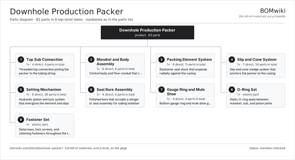
| # | Part | Qty | What it does |
|---|---|---|---|
| 1 | Top Sub Connection 4 parts | 1× | Threaded top connection joining the packer to the tubing string |
| 2 | Mandrel and Body Assembly 6 parts | 1× | Central body and flow conduit that carries all other subsystems |
| 3 | Packing Element System 6 parts | 1× | Elastomer seal stack that expands radially against the casing |
| 4 | Slip and Cone System 7 parts | 1× | Slip and cone wedge system that anchors the packer to the casing |
| 5 | Setting Mechanism 9 parts | 1× | Hydraulic piston and lock system that energizes the element and slips |
| 6 | Seal Bore Assembly 4 parts | 1× | Polished bore that accepts a stinger or seal assembly for tubing isolation |
| 7 | Gauge Ring and Mule Shoe 4 parts | 1× | Bottom gauge ring and mule shoe guiding the tool past casing collars |
| 8 | O-Ring Set | 1× | Static O-ring seals between mandrel, sub, and piston joints |
| 9 | Fastener Set | 1× | Setscrews, lock screws, and retaining fasteners throughout the tool |
3D model
No 3D model yet. Have a CAD file of this? Add a 3D model. STL renders right on this page; STEP, FreeCAD, and OpenSCAD sources are welcome too (openly licensed, like all 3D models on BOMwiki).
Build & assembly graph
expand / collapse · shared sub-assemblies converge · links to related products · est. labourTap an assembly to expand/collapse · tap a part to open it · use “Open page” for any node · drag to pan, scroll to zoom.
Bill of materials for Downhole Production Packer
9 top-level lines · 49 rows shown · 83 parts total · indented to 3 levels| # | Item / sub-assembly | Part no. | Qty/assy | Ext. qty | Parts | Type |
|---|---|---|---|---|---|---|
| 1 | Top Sub Connection 4 parts | dhp-top-sub | 1× | 1 | 4 | assembly |
| 1.1 | Top Sub Body | dhp-top-sub-body | 1× | 1 | · | part |
| 1.2 | Tubing Thread Profile | dhp-tubing-thread | 1× | 1 | · | part |
| 1.3 | Thread Protector Cap | dhp-top-thread-protector | 1× | 1 | · | part |
| 1.4 | O-Ring Set | oring-set | 1× | 1 | · | part |
| 2 | Mandrel and Body Assembly 6 parts | dhp-mandrel-asm | 1× | 1 | 8 | assembly |
| 2.1 | Packer Mandrel | dhp-mandrel | 1× | 1 | · | part |
| 2.2 | Body Lock Ring | dhp-body-lock-ring | 1× | 1 | · | part |
| 2.3 | Bypass Port | dhp-bypass-port | 2× | 2 | · | part |
| 2.4 | Bypass Sleeve | dhp-bypass-sleeve | 1× | 1 | · | part |
| 2.5 | Mandrel Load Shoulder | dhp-mandrel-shoulder | 1× | 1 | · | part |
| 2.6 | O-Ring Set | oring-set | 2× | 2 | · | part |
| 3 | Packing Element System 6 parts | dhp-packing-element | 1× | 1 | 11 | assembly |
| 3.1 | Center Sealing Element | dhp-element-center | 1× | 1 | · | part |
| 3.2 | End Sealing Element | dhp-element-end | 2× | 2 | · | part |
| 3.3 | Backup Ring | dhp-backup-ring | 2× | 2 | · | part |
| 3.4 | Anti-Extrusion Ring | dhp-anti-extrusion-ring | 2× | 2 | · | part |
| 3.5 | Element Spacer | dhp-element-spacer | 2× | 2 | · | part |
| 3.6 | Element Gauge Ring | dhp-element-gauge-ring | 2× | 2 | · | part |
| 4 | Slip and Cone System 7 parts | dhp-slip-cone-asm | 1× | 1 | 24 | assembly |
| 4.1 | Upper Slip Segment | dhp-upper-slip | 6× | 6 | · | part |
| 4.2 | Lower Slip Segment | dhp-lower-slip | 6× | 6 | · | part |
| 4.3 | Upper Cone | dhp-upper-cone | 1× | 1 | · | part |
| 4.4 | Lower Cone | dhp-lower-cone | 1× | 1 | · | part |
| 4.5 | Slip Retainer Band | dhp-slip-retainer | 2× | 2 | · | part |
| 4.6 | Slip Leaf Spring | dhp-slip-spring | 6× | 6 | · | part |
| 4.7 | Coil Spring | coil-spring | 2× | 2 | · | part |
| 5 | Setting Mechanism 9 parts | dhp-setting-mechanism | 1× | 1 | 26 | assembly |
| 5.1 | Setting Piston | dhp-setting-piston | 1× | 1 | · | part |
| 5.2 | Setting Cylinder | dhp-setting-cylinder | 1× | 1 | · | part |
| 5.3 | Setting Shear Pin | dhp-shear-pin | 4× | 4 | · | part |
| 5.4 | Run-In Shear Screw | dhp-shear-screw | 6× | 6 | · | part |
| 5.5 | Setting Sleeve | dhp-setting-sleeve | 1× | 1 | · | part |
| 5.6 | Hold-Down Button | dhp-holddown-button | 8× | 8 | · | part |
| 5.7 | Atmospheric Chamber | dhp-atmospheric-chamber | 1× | 1 | · | part |
| 5.8 | Pressure Sensor | pressure-sensor | 1× | 1 | · | part |
| 5.9 | O-Ring Set | oring-set | 3× | 3 | · | part |
| 6 | Seal Bore Assembly 4 parts | dhp-seal-bore-asm | 1× | 1 | 4 | assembly |
| 6.1 | Polished Seal Bore | dhp-seal-bore | 1× | 1 | · | part |
| 6.2 | Seal Bore Extension | dhp-seal-bore-extension | 1× | 1 | · | part |
| 6.3 | Seal Bore Coupling | dhp-seal-bore-coupling | 1× | 1 | · | part |
| 6.4 | No-Go Shoulder | dhp-no-go-shoulder | 1× | 1 | · | part |
| 7 | Gauge Ring and Mule Shoe 4 parts | dhp-gauge-mule-asm | 1× | 1 | 4 | assembly |
| 7.1 | Bottom Gauge Ring | dhp-gauge-ring | 1× | 1 | · | part |
| 7.2 | Mule Shoe Guide | dhp-mule-shoe | 1× | 1 | · | part |
| 7.3 | Lower Port and Plug | dhp-bull-plug-port | 1× | 1 | · | part |
| 7.4 | Fastener Set | fastener-set | 1× | 1 | · | part |
| 8 | O-Ring Set | oring-set | 1× | 1 | · | part |
| 9 | Fastener Set | fastener-set | 1× | 1 | · | part |
Related products
same domain, ranked by shared parts Amine Gas Sweetening Unit
3,543 parts · shares 1 with this page
Amine Gas Sweetening Unit
3,543 parts · shares 1 with this page
 Condensate Stabilizer Column
2,234 parts · shares 1 with this page
Condensate Stabilizer Column
2,234 parts · shares 1 with this page
 Floating-Roof Storage Tank
144 parts · shares 1 with this page
Gas Lift Mandrel and Valve
58 parts · shares 1 with this page
Floating-Roof Storage Tank
144 parts · shares 1 with this page
Gas Lift Mandrel and Valve
58 parts · shares 1 with this page
 Gas Metering Skid
1,491 parts · shares 1 with this page
Gas Metering Skid
1,491 parts · shares 1 with this page
 Gas Pressure Regulating Station
133 parts · shares 1 with this page
Gas Pressure Regulating Station
133 parts · shares 1 with this page
Sourcing: possible vendors
Browse the supplier directory → Prices, MOQ, and lead times are algorithmic estimates, not quotes, and not claims about these companies. Company mappings are curated by keyword; est. price band $10k–$50M. How estimates work| Vendor | HQ | Specialty | MOQ | Lead time |
|---|---|---|---|---|
|
🇺🇸SLB
slb.com ↗
|
Houston, US | Oilfield services & equipment | made to order | 24–48 wks |
| halliburton.com ↗ | Houston, US | Oilfield services | made to order | 24–48 wks |
| bakerhughes.com ↗ | Houston, US | Energy technology | made to order | 24–48 wks |
|
🇺🇸NOV
nov.com ↗
|
Houston, US | Drilling equipment | made to order | 24–48 wks |
| technipfmc.com ↗ | London, GB | Subsea & surface systems | made to order | 24–48 wks |
1,114-word article