Reciprocating Gas Compressor Package
ProductOverview
A reciprocating gas compressor package is a self-contained skid that takes low-pressure field gas and raises it to whatever pressure the next step needs: feeding a gathering line, boosting a pipeline, or injecting gas back into a reservoir for pressure maintenance. Everything needed to run unattended in a remote location sits on one base, which is why operators buy the whole package rather than separate machines. The same gas it compresses also fuels the engine that drives it.
The package is built around a positive-displacement compressor: a piston sweeps a fixed cylinder volume and squeezes the gas charge into a smaller space, raising its pressure. This suits the high pressure ratios and modest flows of field gas service, where a centrifugal machine would struggle. Multiple stages with cooling between them let the package reach high discharge pressure without overheating the gas.
Compressor frame and running gear
The Compressor Frame is the heart of the machine. A cast Frame Casting crankcase houses a forged Crankshaft turning in Main Bearing journals. Each crank throw drives a Connecting Rod down to a Crosshead, a sliding block that keeps the piston rod moving in a straight line even as the rod swings through its arc. That straight-line guidance is what lets a recip compressor use a long horizontal cylinder without side-loading the piston.
Compression happens in the Cylinder Assembly. Inside the Cylinder Body, a Piston driven by the Piston Rod sweeps the gas. As the piston pulls back, the Suction Valve opens and draws in a fresh charge; as it drives forward, that valve shuts, pressure builds, and the Discharge Valve lifts to release the compressed gas. The piston seals against the bore with a set of Piston Ring elements and rides on Rider Ring bands that carry its weight off the cylinder wall. Where the rod passes out of the cylinder, a Packing Case of stacked sealing rings keeps the gas from leaking along the rod.
Driver, cooling and gas conditioning
Power comes from the Gas-Engine Driver, a spark-ignited gas engine burning a slipstream of the field gas. Its Engine Block carries a bank of Power Cylinder units fed by Turbocharger blowers, and a Flywheel couples the engine to the compressor while smoothing out the torque pulses. The Ignition System fires a Spark Plug in each cylinder through individual Ignition Coil units, and a Speed Governor holds engine speed steady as the gas load changes.
Compressing gas heats it, so the Cooler is essential. Its banks of Cooler Bay finned tubes, swept by large Cooler Fan units, cool the gas between stages and after the final stage, and also reject the engine jacket-water heat. Cooling the gas between stages is what makes multi-stage compression efficient, because cooler gas takes less work to compress.
Liquids are dangerous in a recip cylinder, so the Scrubber Set removes them first. The Suction Scrubber knocks out entrained liquid before the first cylinder, and the Interstage Scrubber catches condensate that drops out during interstage cooling. Each uses a Mist Pad to coalesce fine droplets, and a Dump Valve drains what collects.
Lubrication and control
The Lubrication System keeps two separate oil duties running. A Frame Oil Pump circulates oil through the crankcase bearings, while a set of Lube Injector pumps meter a small, precise oil flow into each cylinder bore and packing case to seal and protect the sliding surfaces. The oil passes through a Oil Filter and a Oil Cooler to stay clean and in temperature.
The Control Panel runs the package and protects it. A Compressor PLC handles the timed start sequence, capacity control and the safety logic, and an operator works through an HMI screen. Process pressure transmitters and Vibration Switch units feed the shutdown system, so a fault, a high discharge temperature, low oil pressure or excess vibration, trips the unit before damage spreads.
Skid, pulsation and use
Everything mounts on the Skid Base. A welded Skid Frame carries the loads, and the Process Piping ties scrubbers, cylinders and coolers together. Because a recip compressor delivers gas in pulses rather than a steady stream, Pulsation Bottle volumes on the suction and discharge of each cylinder smooth those pulses so the piping does not shake itself apart.
Packages are sized by driver power, from a couple hundred horsepower on a single well up to two thousand horsepower on a gathering header, and by the number of stages needed to reach the discharge pressure. Field gas gathering uses low pressure ratios in one or two stages, while gas injection for pressure maintenance can need three stages to reach reservoir pressure. The skid-mounted form is what lets an operator truck a complete, pre-tested machine to a remote pad and have it running in days.
Reciprocating Gas Compressor Package parts and their functions
8 top-level parts · 187 parts in total · full bill of materials below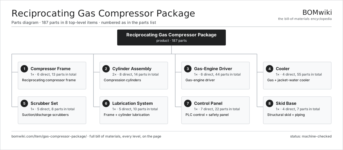
| # | Part | Qty | What it does |
|---|---|---|---|
| 1 | Compressor Frame 6 parts | 1× | Reciprocating compressor frame |
| 2 | Cylinder Assembly 8 parts | 2× | Compression cylinders |
| 3 | Gas-Engine Driver 6 parts | 1× | Gas-engine driver |
| 4 | Cooler 4 parts | 1× | Gas + jacket-water cooler |
| 5 | Scrubber Set 5 parts | 1× | Suction/discharge scrubbers |
| 6 | Lubrication System 5 parts | 1× | Frame + cylinder lubrication |
| 7 | Control Panel 7 parts | 1× | PLC control + safety panel |
| 8 | Skid Base 4 parts | 1× | Structural skid + piping |
3D model
No 3D model yet. Have a CAD file of this? Add a 3D model. STL renders right on this page; STEP, FreeCAD, and OpenSCAD sources are welcome too (openly licensed, like all 3D models on BOMwiki).
Build & assembly graph
expand / collapse · shared sub-assemblies converge · links to related products · est. labourTap an assembly to expand/collapse · tap a part to open it · use “Open page” for any node · drag to pan, scroll to zoom.
Bill of materials for Reciprocating Gas Compressor Package
8 top-level lines · 62 rows shown · 187 parts total · indented to 3 levels| # | Item / sub-assembly | Part no. | Qty/assy | Ext. qty | Parts | Type |
|---|---|---|---|---|---|---|
| 1 | Compressor Frame 6 parts | gcp-compressor-frame | 1× | 1 | 13 | assembly |
| 1.1 | Frame Casting | gcp-frame-casting | 1× | 1 | · | part |
| 1.2 | Crankshaft | gcp-crankshaft | 1× | 1 | · | part |
| 1.3 | Connecting Rod | gcp-connecting-rod | 2× | 2 | · | part |
| 1.4 | Crosshead | gcp-crosshead | 2× | 2 | · | part |
| 1.5 | Main Bearing | gcp-main-bearing | 3× | 3 | · | part |
| 1.6 | Ball Bearing | ball-bearing | 4× | 4 | · | part |
| 2 | Cylinder Assembly 8 parts | gcp-cylinder-assembly | 2× | 2 | 14 | assembly |
| 2.1 | Cylinder Body | gcp-cylinder-body | 1× | 2 | · | part |
| 2.2 | Piston | gcp-piston | 1× | 2 | · | part |
| 2.3 | Piston Rod | gcp-piston-rod | 1× | 2 | · | part |
| 2.4 | Suction Valve | gcp-suction-valve | 2× | 4 | · | part |
| 2.5 | Discharge Valve | gcp-discharge-valve | 2× | 4 | · | part |
| 2.6 | Piston Ring | gcp-piston-ring | 4× | 8 | · | part |
| 2.7 | Rider Ring | gcp-rider-ring | 2× | 4 | · | part |
| 2.8 | Packing Case | gcp-packing-case | 1× | 2 | · | part |
| 3 | Gas-Engine Driver 6 parts | gcp-driver-engine | 1× | 1 | 44 | assembly |
| 3.1 | Engine Block | gcp-engine-block | 1× | 1 | · | part |
| 3.2 | Power Cylinder | gcp-power-cylinder | 12× | 12 | · | part |
| 3.3 | Turbocharger | gcp-turbocharger | 2× | 2 | · | part |
| 3.4 | Ignition System 5 parts | gcp-ignition-system | 1× | 1 | 27 | assembly |
| 3.4.1 | Spark Plug | gcp-spark-plug | 12× | 12 | · | part |
| 3.4.2 | Ignition Coil | gcp-ignition-coil | 12× | 12 | · | part |
| 3.4.3 | Bare PCB | pcb-bare | 1× | 1 | · | part |
| 3.4.4 | Microcontroller | mcu | 1× | 1 | · | part |
| 3.4.5 | Wire Bundle | wire-bundle | 1× | 1 | · | part |
| 3.5 | Speed Governor | gcp-governor | 1× | 1 | · | part |
| 3.6 | Flywheel | gcp-flywheel | 1× | 1 | · | part |
| 4 | Cooler 4 parts | gcp-cooler | 1× | 1 | 55 | assembly |
| 4.1 | Cooler Bay | gcp-cooler-bay | 3× | 3 | · | part |
| 4.2 | Cooler Fan | gcp-cooler-fan | 2× | 2 | · | part |
| 4.3 | Servo Motor 4 parts | servo-motor | 2× | 2 | 24 | assembly |
| 4.3.1 | Stator Assembly 3 parts + deeper › | stator-assembly | 1× | 2 | 3 | assembly |
| 4.3.2 | Rotor Assembly 4 parts + deeper › | rotor-assembly | 1× | 2 | 19 | assembly |
| 4.3.3 | Encoder | encoder | 1× | 2 | · | part |
| 4.3.4 | Motor Housing | motor-housing | 1× | 2 | · | part |
| 4.4 | Drive Belt | drive-belt | 2× | 2 | · | part |
| 5 | Scrubber Set 5 parts | gcp-scrubber-set | 1× | 1 | 8 | assembly |
| 5.1 | Suction Scrubber | gcp-suction-scrubber | 1× | 1 | · | part |
| 5.2 | Interstage Scrubber | gcp-interstage-scrubber | 1× | 1 | · | part |
| 5.3 | Mist Pad | gcp-mist-pad | 2× | 2 | · | part |
| 5.4 | Dump Valve | gcp-dump-valve | 2× | 2 | · | part |
| 5.5 | Relief Valve | gcp-relief-valve | 2× | 2 | · | part |
| 6 | Lubrication System 5 parts | gcp-lube-system | 1× | 1 | 10 | assembly |
| 6.1 | Frame Oil Pump | gcp-frame-oil-pump | 1× | 1 | · | part |
| 6.2 | Lube Injector | gcp-lube-injector | 4× | 4 | · | part |
| 6.3 | Oil Filter | gcp-oil-filter | 2× | 2 | · | part |
| 6.4 | Oil Cooler | gcp-oil-cooler | 1× | 1 | · | part |
| 6.5 | Pressure Sensor | pressure-sensor | 2× | 2 | · | part |
| 7 | Control Panel 7 parts | gcp-control-panel | 1× | 1 | 22 | assembly |
| 7.1 | Compressor PLC | gcp-plc | 1× | 1 | · | part |
| 7.2 | LCD Panel | lcd-panel | 1× | 1 | · | part |
| 7.3 | Power Supply | power-supply | 1× | 1 | · | part |
| 7.4 | Pressure Sensor | pressure-sensor | 6× | 6 | · | part |
| 7.5 | Vibration Switch | gcp-vibration-switch | 4× | 4 | · | part |
| 7.6 | Relay | relay | 8× | 8 | · | part |
| 7.7 | Wire Bundle | wire-bundle | 1× | 1 | · | part |
| 8 | Skid Base 4 parts | gcp-skid-base | 1× | 1 | 7 | assembly |
| 8.1 | Skid Frame | gcp-skid-frame | 1× | 1 | · | part |
| 8.2 | Pulsation Bottle | gcp-pulsation-bottle | 4× | 4 | · | part |
| 8.3 | Process Piping | gcp-process-piping | 1× | 1 | · | part |
| 8.4 | Fastener Set | fastener-set | 1× | 1 | · | part |
Related products
same domain, ranked by shared parts Drilling Mud Degasser
154 parts · shares 12 with this page
CO2 Injection Pump
463 parts · shares 14 with this page
Drilling Mud Degasser
154 parts · shares 12 with this page
CO2 Injection Pump
463 parts · shares 14 with this page
 Drilling Mud Mixing System
135 parts · shares 14 with this page
Drilling Mud Mixing System
135 parts · shares 14 with this page
 Gas Engine Driven Compressor
217 parts · shares 14 with this page
Gas Engine Driven Compressor
217 parts · shares 14 with this page
 Oilwell Cementing Unit
902 parts · shares 14 with this page
Oilwell Cementing Unit
902 parts · shares 14 with this page
 Wireline Logging Unit
189 parts · shares 14 with this page
Wireline Logging Unit
189 parts · shares 14 with this page
Sourcing: possible vendors
Browse the supplier directory → Prices, MOQ, and lead times are algorithmic estimates, not quotes, and not claims about these companies. Company mappings are curated by keyword; est. price band $10k–$50M. How estimates work| Vendor | HQ | Specialty | MOQ | Lead time |
|---|---|---|---|---|
|
🇺🇸SLB
slb.com ↗
|
Houston, US | Oilfield services & equipment | made to order | 24–48 wks |
| halliburton.com ↗ | Houston, US | Oilfield services | made to order | 24–48 wks |
| bakerhughes.com ↗ | Houston, US | Energy technology | made to order | 24–48 wks |
|
🇺🇸NOV
nov.com ↗
|
Houston, US | Drilling equipment | made to order | 24–48 wks |
| technipfmc.com ↗ | London, GB | Subsea & surface systems | made to order | 24–48 wks |
840-word article