Electrostatic Coalescer
ProductOverview
An electrostatic coalescer is a vessel that removes emulsified water from crude oil by applying a high-voltage electric field to the oil. After gravity separation has taken out the free water, the oil still holds a fine emulsion of tiny water droplets that are too small to settle on their own. These droplets carry dissolved salts and they must be removed before the oil meets pipeline or sales specification, which usually limits basic sediment and water to half a percent or less. The electric field forces the small droplets to merge into large ones that fall out by gravity, a process called electrostatic coalescence.
The coalescer is the dehydration stage of an oil treating train. It typically follows a Free Water Knockout Drum and any heating stage, and on heavier crudes it may work alongside a heater treater. In refineries the same physics drives the Crude Oil Desalter, which adds wash water to remove salt, while a field coalescer is aimed mainly at meeting the water content limit on produced crude. The Pressure Vessel holds the oil at a controlled temperature and pressure while the field does its work.
How the field coalesces water
The dispersed water droplets in crude are conductive, and the surrounding oil is an insulator. When the Electrode Array array is energized, the field polarizes each water droplet, creating positive and negative ends. Neighboring droplets then attract one another end to end and merge. The field also makes droplets vibrate and elongate, which thins the oil film between droplets and helps them touch and combine. As droplets grow, their settling speed rises sharply with the square of their diameter, so a droplet that has merged a hundredfold settles thousands of times faster and quickly drops out of the rising oil.
Several field types are used. An AC field is simple and works well for moderate water cuts. A DC field reaches deeper into the emulsion and suits tight or high-water emulsions. Dual-polarity and modulated fields combine an AC field near the interface, where conductivity is high, with a DC field higher up where the oil is drier, getting good coalescence across the whole vessel without excessive current draw.
Power supply and electrical design
The field is fed by the High-Voltage Power Unit, a transformer-rectifier set that steps the supply voltage up to between 15,000 and 40,000 volts. A current-limiting reactor is built into the supply because conductive water can momentarily bridge the electrodes and try to draw a large current; the reactor holds that current to a safe value and lets the field recover once the bridge clears. A control board and microcontroller monitor the field and adjust the voltage to match the emulsion. The electrodes themselves hang on ceramic or composite standoff insulators and are fed through sealed entrance bushings in the shell, with the vessel grounded so the field exists only between the energized array and the conductive water layer below.
Internal flow and water removal
Even flow through the field is essential, so the Distribution Internals internals spread the inlet across the vessel with a perforated spreader and distributor plates, and gather the dehydrated oil at the top through a collector header. The coalesced water settles into the Water Collection Section at the bottom, where a collector header draws it off through a control valve. A mud wash header along the bottom periodically flushes the settled solids and sediment that would otherwise build up and disturb the field. A vortex breaker at the water outlet keeps the drain from pulling oil down with the water.
Interface control and safety
The oil-water interface must stay below the electrodes. If the conductive water rises into the array it shorts the field and stops coalescence, and it can trip the power supply. The Control System system uses an interface transmitter to track the boundary and modulates the water dump valve to hold it steady, with sight glasses and level switches as backup. Electrical interlocks de-energize the field if the interface gets too high or an access door is opened, and a current monitor flags sustained arcing. The Pressure and Relief train protects the vessel from overpressure with an ASME relief valve and a backup rupture disc.
Variants and use
Horizontal coalescers give a large interface area and suit high throughput, while vertical units save plot space and handle slugging. Compact electrostatic coalescers built into a single pipe section, sometimes called inline coalescers, treat oil in the flowline without a large vessel. The technology is used both onshore and offshore, where weight and footprint drive the choice of compact designs. By delivering crude that meets the water specification, the coalescer protects pipelines from corrosion, avoids penalties for off-spec oil, and reduces the volume that must be transported to refineries.
Electrostatic Coalescer parts and their functions
8 top-level parts · 80 parts in total · full bill of materials below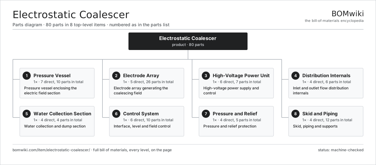
| # | Part | Qty | What it does |
|---|---|---|---|
| 1 | Pressure Vessel 7 parts | 1× | Pressure vessel enclosing the electric field section |
| 2 | Electrode Array 5 parts | 1× | Electrode array generating the coalescing field |
| 3 | High-Voltage Power Unit 6 parts | 1× | High-voltage power supply and control |
| 4 | Distribution Internals 4 parts | 1× | Inlet and outlet flow distribution internals |
| 5 | Water Collection Section 4 parts | 1× | Water collection and dump section |
| 6 | Control System 6 parts | 1× | Interface, level and field control |
| 7 | Pressure and Relief 4 parts | 1× | Pressure and relief protection |
| 8 | Skid and Piping 4 parts | 1× | Skid, piping and supports |
3D model
No 3D model yet. Have a CAD file of this? Add a 3D model. STL renders right on this page; STEP, FreeCAD, and OpenSCAD sources are welcome too (openly licensed, like all 3D models on BOMwiki).
Build & assembly graph
expand / collapse · shared sub-assemblies converge · links to related products · est. labourTap an assembly to expand/collapse · tap a part to open it · use “Open page” for any node · drag to pan, scroll to zoom.
Bill of materials for Electrostatic Coalescer
8 top-level lines · 48 rows shown · 80 parts total · indented to 3 levels| # | Item / sub-assembly | Part no. | Qty/assy | Ext. qty | Parts | Type |
|---|---|---|---|---|---|---|
| 1 | Pressure Vessel 7 parts | electrostatic-coalescer-vessel | 1× | 1 | 10 | assembly |
| 1.1 | Shell Course Ring | electrostatic-coalescer-shell | 2× | 2 | · | part |
| 1.2 | Vessel Head | electrostatic-coalescer-head | 2× | 2 | · | part |
| 1.3 | Nozzle Set | electrostatic-coalescer-nozzle-set | 1× | 1 | · | part |
| 1.4 | Support | electrostatic-coalescer-saddle | 2× | 2 | · | part |
| 1.5 | Manway | electrostatic-coalescer-manway | 1× | 1 | · | part |
| 1.6 | Internal Coating | electrostatic-coalescer-coating | 1× | 1 | · | part |
| 1.7 | Fastener Set | fastener-set | 1× | 1 | · | part |
| 2 | Electrode Array 5 parts | electrostatic-coalescer-electrode | 1× | 1 | 26 | assembly |
| 2.1 | Electrode Plate | electrostatic-coalescer-electrode-plate | 4× | 4 | · | part |
| 2.2 | Electrode Hanger | electrostatic-coalescer-electrode-hanger | 8× | 8 | · | part |
| 2.3 | Standoff Insulator | electrostatic-coalescer-insulator | 8× | 8 | · | part |
| 2.4 | Power Entrance Bushing | electrostatic-coalescer-bushing | 2× | 2 | · | part |
| 2.5 | Ground Strap | electrostatic-coalescer-ground-strap | 4× | 4 | · | part |
| 3 | High-Voltage Power Unit 6 parts | electrostatic-coalescer-power-unit | 1× | 1 | 7 | assembly |
| 3.1 | Step-Up Transformer | electrostatic-coalescer-transformer | 1× | 1 | · | part |
| 3.2 | Rectifier | electrostatic-coalescer-rectifier | 1× | 1 | · | part |
| 3.3 | Current-Limiting Reactor | electrostatic-coalescer-reactor | 1× | 1 | · | part |
| 3.4 | High-Voltage Bushing | electrostatic-coalescer-hv-bushing | 2× | 2 | · | part |
| 3.5 | Bare PCB | pcb-bare | 1× | 1 | · | part |
| 3.6 | Microcontroller | mcu | 1× | 1 | · | part |
| 4 | Distribution Internals 4 parts | electrostatic-coalescer-distribution | 1× | 1 | 6 | assembly |
| 4.1 | Inlet Spreader | electrostatic-coalescer-inlet-spreader | 1× | 1 | · | part |
| 4.2 | Distributor Plate | electrostatic-coalescer-distributor-plate | 2× | 2 | · | part |
| 4.3 | Oil Collector Header | electrostatic-coalescer-oil-collector | 1× | 1 | · | part |
| 4.4 | Flow Baffle | electrostatic-coalescer-baffle | 2× | 2 | · | part |
| 5 | Water Collection Section 4 parts | electrostatic-coalescer-water-section | 1× | 1 | 4 | assembly |
| 5.1 | Water Collector Header | electrostatic-coalescer-water-collector | 1× | 1 | · | part |
| 5.2 | Water Dump Valve | electrostatic-coalescer-water-dump-valve | 1× | 1 | · | part |
| 5.3 | Mud Wash Header | electrostatic-coalescer-mud-wash | 1× | 1 | · | part |
| 5.4 | Vortex Breaker | electrostatic-coalescer-vortex-breaker | 1× | 1 | · | part |
| 6 | Control System 6 parts | electrostatic-coalescer-control | 1× | 1 | 10 | assembly |
| 6.1 | Interface Transmitter | electrostatic-coalescer-interface-transmitter | 1× | 1 | · | part |
| 6.2 | Interface Controller | electrostatic-coalescer-controller | 1× | 1 | · | part |
| 6.3 | Field Current Monitor | electrostatic-coalescer-current-monitor | 1× | 1 | · | part |
| 6.4 | Sight Glass | electrostatic-coalescer-sight-glass | 2× | 2 | · | part |
| 6.5 | Relay | relay | 3× | 3 | · | part |
| 6.6 | Level Switch | electrostatic-coalescer-level-switch | 2× | 2 | · | part |
| 7 | Pressure and Relief 4 parts | electrostatic-coalescer-relief | 1× | 1 | 5 | assembly |
| 7.1 | Relief Valve | electrostatic-coalescer-relief-valve | 1× | 1 | · | part |
| 7.2 | Rupture Disc | electrostatic-coalescer-rupture-disc | 1× | 1 | · | part |
| 7.3 | Pressure Sensor | pressure-sensor | 2× | 2 | · | part |
| 7.4 | Vent Valve | electrostatic-coalescer-vent-valve | 1× | 1 | · | part |
| 8 | Skid and Piping 4 parts | electrostatic-coalescer-skid | 1× | 1 | 12 | assembly |
| 8.1 | Skid Frame | electrostatic-coalescer-skid-frame | 1× | 1 | · | part |
| 8.2 | Pipe Spool | electrostatic-coalescer-pipe-spool | 4× | 4 | · | part |
| 8.3 | Pipe Support | electrostatic-coalescer-pipe-support | 6× | 6 | · | part |
| 8.4 | Walkway and Ladder | electrostatic-coalescer-walkway | 1× | 1 | · | part |
Sourcing: possible vendors
Browse the supplier directory → Prices, MOQ, and lead times are algorithmic estimates, not quotes, and not claims about these companies. Company mappings are curated by keyword; est. price band $10k–$50M. How estimates work| Vendor | HQ | Specialty | MOQ | Lead time |
|---|---|---|---|---|
|
🇺🇸SLB
slb.com ↗
|
Houston, US | Oilfield services & equipment | made to order | 24–48 wks |
| halliburton.com ↗ | Houston, US | Oilfield services | made to order | 24–48 wks |
| bakerhughes.com ↗ | Houston, US | Energy technology | made to order | 24–48 wks |
|
🇺🇸NOV
nov.com ↗
|
Houston, US | Drilling equipment | made to order | 24–48 wks |
| technipfmc.com ↗ | London, GB | Subsea & surface systems | made to order | 24–48 wks |
807-word article