Three-Phase Production Separator
ProductOverview
A three-phase production separator is a pressure vessel that receives the raw wellstream from one or more wells and divides it into three streams: gas, oil and produced water. It sits early in the surface facility, downstream of the choke and any Wellhead Sand Separator stage, and ahead of treating, dehydration and metering equipment. The vessel relies on gravity, residence time and engineered internals to let the phases separate by density: gas rises and exits the top, oil floats on water and overflows a weir into a separate compartment, and the denser produced water settles to the bottom.
Most production separators are horizontal because the long liquid surface area shortens the distance a droplet must rise or fall, which improves separation of close-density oil and water. The vessel is sized per API 12J for both gas-handling capacity and liquid retention time, typically 3 to 10 minutes of liquid holdup so that emulsions have time to break and gas bubbles can escape the liquid. The Pressure Vessel Shell is built to ASME Section VIII so it can hold the operating pressure, which commonly ranges from a few hundred psig up to 1,440 psig for high-pressure gas wells.
How separation works
Fluid enters through the Inlet Diverter Assembly, where an inlet diverter breaks the momentum of the high-velocity wellstream. This first stage knocks the bulk liquid out of the gas immediately and prevents the jet from churning the liquid pool, which would re-entrain water into the oil. The gas continues along the top of the vessel toward the gas outlet, while the liquid falls into the pool and begins to stratify.
In the liquid section, the Separation Internals do the fine work. A corrugated coalescing plate pack gives small water droplets a large surface area on which to merge into larger droplets that settle faster. Oil flows the length of the vessel and spills over the Weir Plate into the oil bucket, while water remains on the upstream side of the weir. Vortex breakers at the liquid outlets stop a swirling drain from pulling gas down into the liquid lines. A sand jetting header at the bottom fluidizes solids so they can be flushed, important for wells that also produce sand.
Before the gas leaves, it passes through the Mist Extractor. A knitted wire mesh pad or a chevron vane pack captures the fine liquid droplets the gas still carries, typically removing 99 percent of droplets larger than 10 microns. The captured liquid drains back into the pool, and clean gas exits to compression or the gas sales line.
Level and pressure control
Two liquid levels must be held at once: the oil-water interface and the oil level above the weir. The Level Control System system uses an interface transmitter, usually a capacitance probe or a displacer, to sense where oil meets water, and it modulates the water dump valve to keep that interface steady. A second transmitter watches the oil level and drives the oil dump valve. Reflex sight glasses give operators a direct visual check, and high and low level switches trip the shutdown system if a controller fails.
Gas pressure is held by the Pressure Control System system. A back-pressure control valve on the gas outlet throttles to maintain vessel pressure at setpoint, which sets the operating pressure of the whole separation stage. Overpressure protection comes from an ASME relief valve sized for the blocked-outlet and fire cases, often backed up by a rupture disc, and a blowdown valve depressurizes the vessel to flare during an emergency shutdown.
Instrumentation and safety
The Instrumentation and Shutdown package ties the vessel into the facility safety system. Pressure and temperature transmitters report process conditions, local gauges give a field reading, and an inlet shutdown valve closes on a trip signal from the logic solver. The shutdown matrix covers high and low level, high and low pressure, and fire or gas detection, closing the inlet and opening blowdown to bring the vessel to a safe state. Instrument wiring and junction boxes are rated for the hazardous area classification of the site.
Materials and corrosion control
The shell and heads are usually SA-516-70 carbon steel with a corrosion allowance of 1/8 to 1/4 inch. Produced water is often saline and may carry hydrogen sulfide or carbon dioxide, so the water-wetted lower section is the most aggressive environment. An internal epoxy or fusion-bonded coating protects the steel, and for sour service the vessel may use corrosion-resistant alloy cladding and materials selected to resist sulfide stress cracking per NACE MR0175. Removable internals and a bolted manway allow the coalescing pack and demister to be inspected and replaced.
Variants and use
Two-phase separators handle only gas and liquid and omit the interface control and weir, while four-phase units add solids handling. Vertical three-phase separators are used where plot space is tight or where slugging is severe, since the vertical liquid column tolerates surges. On test duty, a smaller version such as the Well Test Separator Skid measures individual well rates. The three-phase separator is the workhorse of upstream surface processing, and its sizing and internals are matched to the gas-oil ratio, water cut and emulsion tendency of the specific field it serves.
Three-Phase Production Separator parts and their functions
8 top-level parts · 76 parts in total · full bill of materials below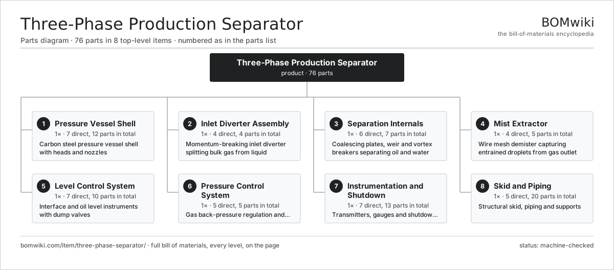
| # | Part | Qty | What it does |
|---|---|---|---|
| 1 | Pressure Vessel Shell 7 parts | 1× | Carbon steel pressure vessel shell with heads and nozzles |
| 2 | Inlet Diverter Assembly 4 parts | 1× | Momentum-breaking inlet diverter splitting bulk gas from liquid |
| 3 | Separation Internals 6 parts | 1× | Coalescing plates, weir and vortex breakers separating oil and water |
| 4 | Mist Extractor 4 parts | 1× | Wire mesh demister capturing entrained droplets from gas outlet |
| 5 | Level Control System 7 parts | 1× | Interface and oil level instruments with dump valves |
| 6 | Pressure Control System 5 parts | 1× | Gas back-pressure regulation and relief train |
| 7 | Instrumentation and Shutdown 7 parts | 1× | Transmitters, gauges and shutdown logic |
| 8 | Skid and Piping 5 parts | 1× | Structural skid, piping and supports |
3D model
No 3D model yet. Have a CAD file of this? Add a 3D model. STL renders right on this page; STEP, FreeCAD, and OpenSCAD sources are welcome too (openly licensed, like all 3D models on BOMwiki).
Build & assembly graph
expand / collapse · shared sub-assemblies converge · links to related products · est. labourTap an assembly to expand/collapse · tap a part to open it · use “Open page” for any node · drag to pan, scroll to zoom.
Bill of materials for Three-Phase Production Separator
8 top-level lines · 53 rows shown · 76 parts total · indented to 3 levels| # | Item / sub-assembly | Part no. | Qty/assy | Ext. qty | Parts | Type |
|---|---|---|---|---|---|---|
| 1 | Pressure Vessel Shell 7 parts | three-phase-separator-vessel | 1× | 1 | 12 | assembly |
| 1.1 | Shell Course Ring | three-phase-separator-shell-ring | 4× | 4 | · | part |
| 1.2 | Vessel Head | three-phase-separator-head | 2× | 2 | · | part |
| 1.3 | Nozzle Set | three-phase-separator-nozzle-set | 1× | 1 | · | part |
| 1.4 | Saddle Support | three-phase-separator-saddle | 2× | 2 | · | part |
| 1.5 | Manway | three-phase-separator-manway | 1× | 1 | · | part |
| 1.6 | Internal Corrosion Coating | three-phase-separator-corrosion-coating | 1× | 1 | · | part |
| 1.7 | Fastener Set | fastener-set | 1× | 1 | · | part |
| 2 | Inlet Diverter Assembly 4 parts | three-phase-separator-inlet-device | 1× | 1 | 4 | assembly |
| 2.1 | Inlet Diverter | three-phase-separator-inlet-diverter | 1× | 1 | · | part |
| 2.2 | Inlet Baffle | three-phase-separator-inlet-baffle | 1× | 1 | · | part |
| 2.3 | Inlet Distributor | three-phase-separator-inlet-distributor | 1× | 1 | · | part |
| 2.4 | Impingement Plate | three-phase-separator-impingement-plate | 1× | 1 | · | part |
| 3 | Separation Internals 6 parts | three-phase-separator-internals | 1× | 1 | 7 | assembly |
| 3.1 | Coalescing Plate Pack | three-phase-separator-coalescing-pack | 1× | 1 | · | part |
| 3.2 | Weir Plate | three-phase-separator-weir-plate | 1× | 1 | · | part |
| 3.3 | Oil Bucket | three-phase-separator-bucket | 1× | 1 | · | part |
| 3.4 | Vortex Breaker | three-phase-separator-vortex-breaker | 2× | 2 | · | part |
| 3.5 | Sand Jetting Header | three-phase-separator-sand-jet | 1× | 1 | · | part |
| 3.6 | Defoaming Pack | three-phase-separator-defoaming-pack | 1× | 1 | · | part |
| 4 | Mist Extractor 4 parts | three-phase-separator-mist-extractor | 1× | 1 | 5 | assembly |
| 4.1 | Wire Mesh Pad | three-phase-separator-mesh-pad | 1× | 1 | · | part |
| 4.2 | Vane Pack | three-phase-separator-vane-pack | 1× | 1 | · | part |
| 4.3 | Demister Support Grid | three-phase-separator-mist-grid | 2× | 2 | · | part |
| 4.4 | Demister Drain Pipe | three-phase-separator-drain-pipe | 1× | 1 | · | part |
| 5 | Level Control System 7 parts | three-phase-separator-level-control | 1× | 1 | 10 | assembly |
| 5.1 | Interface Level Transmitter | three-phase-separator-interface-transmitter | 1× | 1 | · | part |
| 5.2 | Oil Level Transmitter | three-phase-separator-oil-level-transmitter | 1× | 1 | · | part |
| 5.3 | Level Controller | three-phase-separator-level-controller | 2× | 2 | · | part |
| 5.4 | Oil Dump Valve | three-phase-separator-oil-dump-valve | 1× | 1 | · | part |
| 5.5 | Water Dump Valve | three-phase-separator-water-dump-valve | 1× | 1 | · | part |
| 5.6 | Level Sight Glass | three-phase-separator-sight-glass | 2× | 2 | · | part |
| 5.7 | Level Switch | three-phase-separator-level-switch | 2× | 2 | · | part |
| 6 | Pressure Control System 5 parts | three-phase-separator-pressure-control | 1× | 1 | 5 | assembly |
| 6.1 | Back-Pressure Valve | three-phase-separator-back-pressure-valve | 1× | 1 | · | part |
| 6.2 | Pressure Controller | three-phase-separator-pressure-controller | 1× | 1 | · | part |
| 6.3 | Pressure Relief Valve | three-phase-separator-relief-valve | 1× | 1 | · | part |
| 6.4 | Rupture Disc | three-phase-separator-rupture-disc | 1× | 1 | · | part |
| 6.5 | Blowdown Valve | three-phase-separator-blowdown-valve | 1× | 1 | · | part |
| 7 | Instrumentation and Shutdown 7 parts | three-phase-separator-instrumentation | 1× | 1 | 13 | assembly |
| 7.1 | Pressure Sensor | pressure-sensor | 2× | 2 | · | part |
| 7.2 | Temperature Transmitter | three-phase-separator-temperature-transmitter | 1× | 1 | · | part |
| 7.3 | Pressure Gauge | three-phase-separator-pressure-gauge | 3× | 3 | · | part |
| 7.4 | Shutdown Valve | three-phase-separator-sdv | 1× | 1 | · | part |
| 7.5 | Safety Logic Solver | three-phase-separator-logic-solver | 1× | 1 | · | part |
| 7.6 | Wire Bundle | wire-bundle | 1× | 1 | · | part |
| 7.7 | Connector | connector | 4× | 4 | · | part |
| 8 | Skid and Piping 5 parts | three-phase-separator-skid | 1× | 1 | 20 | assembly |
| 8.1 | Skid Frame | three-phase-separator-skid-frame | 1× | 1 | · | part |
| 8.2 | Pipe Spool | three-phase-separator-pipe-spool | 6× | 6 | · | part |
| 8.3 | Pipe Support | three-phase-separator-pipe-support | 8× | 8 | · | part |
| 8.4 | Walkway and Ladder | three-phase-separator-walkway | 1× | 1 | · | part |
| 8.5 | Earthing Boss | three-phase-separator-earth-boss | 4× | 4 | · | part |
Sourcing: possible vendors
Browse the supplier directory → Prices, MOQ, and lead times are algorithmic estimates, not quotes, and not claims about these companies. Company mappings are curated by keyword; est. price band $10k–$50M. How estimates work| Vendor | HQ | Specialty | MOQ | Lead time |
|---|---|---|---|---|
|
🇺🇸SLB
slb.com ↗
|
Houston, US | Oilfield services & equipment | made to order | 24–48 wks |
| halliburton.com ↗ | Houston, US | Oilfield services | made to order | 24–48 wks |
| bakerhughes.com ↗ | Houston, US | Energy technology | made to order | 24–48 wks |
|
🇺🇸NOV
nov.com ↗
|
Houston, US | Drilling equipment | made to order | 24–48 wks |
| technipfmc.com ↗ | London, GB | Subsea & surface systems | made to order | 24–48 wks |
903-word article