Fired Process Heater
ProductOverview
A fired process heater is a furnace that raises the temperature of a process stream by burning fuel and transferring the heat through tube walls to the fluid flowing inside. Almost every refinery process needs heat at a temperature higher than steam can practically deliver, so fired heaters appear throughout the plant: heating crude before the distillation column, reboiling tower bottoms, charging reactors in reforming and hydroprocessing, and reheating streams between stages. The heater is essentially a tube circuit running through a fired box, arranged so the process fluid picks up heat first by radiation from the flame, then by convection from the cooling flue gas.
The unit has two heat-transfer zones. The Radiant Section is the firebox itself, where burner flames heat the tubes mostly by thermal radiation and where the highest tube temperatures occur. Above it the Convection Section recovers more heat from the flue gas before it leaves. The Burner System releases the heat, the Stack and Draft Control system pulls the flue gas through, and the Air Preheat System system recovers waste heat to raise efficiency.
How it works
Fuel and combustion air meet at the Burner units, where the Gas Tip meters fuel gas, or the Oil Gun atomizes fuel oil, into the air stream shaped by the Burner Tile and stabilized by the Flame Holder. The flames fill the firebox with radiant heat. The Radiant Tube tubes lining the walls absorb most of this heat and pass it to the process fluid flowing inside, which enters cool and leaves hot. Tubes are joined by Return Bend bends into long serpentine passes and carried at temperature by cast Tube Support supports and Tube Hanger hangers.
Flue gas leaving the firebox is still hot, so it passes up through the Convection Section. The lowest Shock Tube rows are bare to handle the radiant heat from the firebox, while the upper Convection Tube tubes carry Extended Fin fins that multiply their surface area and pull more heat out of the cooling gas. Process fluid usually flows convection-first, entering the cooler upper tubes and finishing in the hot radiant section. After the convection bank, the cooled flue gas exits through the Breeching and Stack.
Draft and combustion air
The flue gas must be pulled through the heater against the resistance of the tube banks. Natural draft uses the buoyancy of hot gas in the Stack, regulated by the Stack Damper. When natural draft is not enough, an Induced Draft Fan pulls the gas through on the outlet side, a Forced Draft Fan pushes air in on the inlet side, or both work together in a balanced-draft arrangement. The Air Register louvers at each burner trim the air split. Maintaining slightly negative pressure in the firebox keeps flames and flue gas from puffing out through openings while avoiding excessive air infiltration.
Efficiency and heat recovery
Thermal efficiency is the fraction of fired heat that ends up in the process. The biggest loss is sensible heat in the flue gas going up the stack, so the Air Preheat System system recovers it: the Air Preheater transfers flue gas heat to the incoming combustion air, which returns that energy to the firebox and lifts efficiency from the low 80s into the low 90s percent. The Oxygen Analyzer trims excess air to the minimum that still gives complete combustion, since every extra unit of air carries heat out the stack. The Preheater Bypass Damper damper protects the cold end from acid dew-point corrosion when fuel sulfur is high. Convection Sootblower lances keep deposits off the fins so heat transfer does not degrade over a run.
Materials and refractory
Tube metallurgy is set by temperature and service. Chromium-molybdenum alloys such as P5 and P9 handle the moderate temperatures of most refinery duties, while high-temperature services like steam reforming use stainless or cast HK40 supports and tubes. The firebox is lined by the Refractory and Casing system: a Ceramic Fiber Lining insulates the walls and roof, a hard Castable Floor takes spillage and traffic, and the lining is held to the Casing Panel panels by anchors. The casing keeps the firebox sealed so draft control works and heat loss stays low.
Control and safety
The Instrument Package and its Burner Management Controller manage both efficiency and safety. The burner management system enforces a strict sequence: purge the firebox of any accumulated fuel, prove the Pilot Burner flames, light the main burners, and continuously prove every flame with a Flame Scanner, tripping the fuel through the Fuel Gas Train safety shutoff if any flame fails. This logic prevents firebox explosions, the worst hazard of any fired equipment, and follows NFPA 85 and 86. The Tube Skin Thermocouple points watch tube metal temperature against the design limit, since overheating a tube shortens its life through creep or can rupture it. Process control trims the Fuel Control Valve to hold the outlet temperature read by the Process Thermocouple elements. Sized for its duty and protected by sound burner management and tube temperature monitoring, the heater runs continuously between turnarounds set by tube and refractory condition.
Fired Process Heater parts and their functions
8 top-level parts · 438 parts in total · full bill of materials below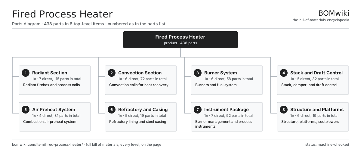
| # | Part | Qty | What it does |
|---|---|---|---|
| 1 | Radiant Section 7 parts | 1× | Radiant firebox and process coils |
| 2 | Convection Section 6 parts | 1× | Convection coils for heat recovery |
| 3 | Burner System 6 parts | 1× | Burners and fuel system |
| 4 | Stack and Draft Control 5 parts | 1× | Stack, damper, and draft control |
| 5 | Air Preheat System 4 parts | 1× | Combustion air preheat system |
| 6 | Refractory and Casing 5 parts | 1× | Refractory lining and steel casing |
| 7 | Instrument Package 7 parts | 1× | Burner management and process instruments |
| 8 | Structure and Platforms 6 parts | 1× | Structure, platforms, sootblowers |
3D model
No 3D model yet. Have a CAD file of this? Add a 3D model. STL renders right on this page; STEP, FreeCAD, and OpenSCAD sources are welcome too (openly licensed, like all 3D models on BOMwiki).
Build & assembly graph
expand / collapse · shared sub-assemblies converge · links to related products · est. labourTap an assembly to expand/collapse · tap a part to open it · use “Open page” for any node · drag to pan, scroll to zoom.
Bill of materials for Fired Process Heater
8 top-level lines · 72 rows shown · 438 parts total · indented to 3 levels| # | Item / sub-assembly | Part no. | Qty/assy | Ext. qty | Parts | Type |
|---|---|---|---|---|---|---|
| 1 | Radiant Section 7 parts | fph-radiant-section | 1× | 1 | 115 | assembly |
| 1.1 | Radiant Tube | fph-radiant-tube | 40× | 40 | · | part |
| 1.2 | Return Bend | fph-tube-return-bend | 38× | 38 | · | part |
| 1.3 | Tube Support | fph-tube-support | 8× | 8 | · | part |
| 1.4 | Tube Guide | fph-tube-guide | 16× | 16 | · | part |
| 1.5 | Tube Hanger | fph-radiant-hanger | 8× | 8 | · | part |
| 1.6 | Peephole | fph-peephole | 4× | 4 | · | part |
| 1.7 | Crossover Piping | fph-crossover | 1× | 1 | · | part |
| 2 | Convection Section 6 parts | fph-convection-section | 1× | 1 | 72 | assembly |
| 2.1 | Convection Tube | fph-convection-tube | 30× | 30 | · | part |
| 2.2 | Extended Fin | fph-extended-fin | 30× | 30 | · | part |
| 2.3 | Shock Tube | fph-shock-tube | 6× | 6 | · | part |
| 2.4 | Tube Sheet | fph-tube-sheet | 2× | 2 | · | part |
| 2.5 | Header Box | fph-header-box | 2× | 2 | · | part |
| 2.6 | Sootblower | fph-sootblower | 2× | 2 | · | part |
| 3 | Burner System 6 parts | fph-burner-system | 1× | 1 | 58 | assembly |
| 3.1 | Burner 4 parts | fph-burner | 8× | 8 | 4 | assembly |
| 3.1.1 | Burner Tile | fph-burner-tile | 1× | 8 | · | part |
| 3.1.2 | Gas Tip | fph-gas-tip | 1× | 8 | · | part |
| 3.1.3 | Oil Gun | fph-oil-gun | 1× | 8 | · | part |
| 3.1.4 | Flame Holder | fph-flame-holder | 1× | 8 | · | part |
| 3.2 | Pilot Burner | fph-pilot-burner | 8× | 8 | · | part |
| 3.3 | Fuel Gas Train | fph-fuel-gas-train | 1× | 1 | · | part |
| 3.4 | Fuel Oil Train | fph-fuel-oil-train | 1× | 1 | · | part |
| 3.5 | Flame Scanner | fph-flame-scanner | 8× | 8 | · | part |
| 3.6 | Air Register | fph-burner-register | 8× | 8 | · | part |
| 4 | Stack and Draft Control 5 parts | fph-stack-draft | 1× | 1 | 32 | assembly |
| 4.1 | Stack | fph-stack | 1× | 1 | · | part |
| 4.2 | Stack Damper | fph-stack-damper | 1× | 1 | · | part |
| 4.3 | Damper Actuator | fph-damper-actuator | 1× | 1 | · | part |
| 4.4 | Induced Draft Fan 4 parts | fph-id-fan | 1× | 1 | 28 | assembly |
| 4.4.1 | Fan Impeller | fph-fan-impeller | 1× | 1 | · | part |
| 4.4.2 | Fan Housing | fph-fan-housing | 1× | 1 | · | part |
| 4.4.3 | Ball Bearing | ball-bearing | 2× | 2 | · | part |
| 4.4.4 | Servo Motor 4 parts + deeper › | servo-motor | 1× | 1 | 24 | assembly |
| 4.5 | Breeching | fph-breeching | 1× | 1 | · | part |
| 5 | Air Preheat System 4 parts | fph-air-preheat | 1× | 1 | 31 | assembly |
| 5.1 | Air Preheater | fph-air-preheater | 1× | 1 | · | part |
| 5.2 | Forced Draft Fan 4 parts | fph-fd-fan | 1× | 1 | 28 | assembly |
| 5.2.1 | Fan Impeller | fph-fan-impeller | 1× | 1 | · | part |
| 5.2.2 | Fan Housing | fph-fan-housing | 1× | 1 | · | part |
| 5.2.3 | Ball Bearing | ball-bearing | 2× | 2 | · | part |
| 5.2.4 | Servo Motor 4 parts + deeper › | servo-motor | 1× | 1 | 24 | assembly |
| 5.3 | Air Duct | fph-air-duct | 1× | 1 | · | part |
| 5.4 | Preheater Bypass Damper | fph-preheater-bypass | 1× | 1 | · | part |
| 6 | Refractory and Casing 5 parts | fph-refractory-casing | 1× | 1 | 19 | assembly |
| 6.1 | Ceramic Fiber Lining | fph-ceramic-fiber-lining | 1× | 1 | · | part |
| 6.2 | Castable Floor | fph-castable-floor | 1× | 1 | · | part |
| 6.3 | Casing Panel | fph-casing-panel | 12× | 12 | · | part |
| 6.4 | Refractory Anchor | fph-refractory-anchor | 1× | 1 | · | part |
| 6.5 | Expansion Seal | fph-expansion-seal | 4× | 4 | · | part |
| 7 | Instrument Package 7 parts | fph-instrument-package | 1× | 1 | 92 | assembly |
| 7.1 | Burner Management Controller 6 parts | fph-bms-controller | 1× | 1 | 65 | assembly |
| 7.1.1 | Bare PCB | pcb-bare | 3× | 3 | · | part |
| 7.1.2 | Microcontroller | mcu | 3× | 3 | · | part |
| 7.1.3 | Relay | relay | 16× | 16 | · | part |
| 7.1.4 | Power Supply | power-supply | 2× | 2 | · | part |
| 7.1.5 | Connector | connector | 40× | 40 | · | part |
| 7.1.6 | Wire Bundle | wire-bundle | 1× | 1 | · | part |
| 7.2 | Tube Skin Thermocouple | fph-tube-skin-thermocouple | 12× | 12 | · | part |
| 7.3 | Process Thermocouple | fph-process-thermocouple | 6× | 6 | · | part |
| 7.4 | Oxygen Analyzer | fph-oxygen-analyzer | 1× | 1 | · | part |
| 7.5 | Draft Transmitter | fph-draft-transmitter | 3× | 3 | · | part |
| 7.6 | Pressure Sensor | pressure-sensor | 3× | 3 | · | part |
| 7.7 | Fuel Control Valve | fph-fuel-control-valve | 2× | 2 | · | part |
| 8 | Structure and Platforms 6 parts | fph-structure | 1× | 1 | 19 | assembly |
| 8.1 | Structure Steel | fph-structure-steel | 1× | 1 | · | part |
| 8.2 | Access Platform | fph-platform | 6× | 6 | · | part |
| 8.3 | Access Ladder | fph-ladder | 2× | 2 | · | part |
| 8.4 | External Insulation | fph-external-insulation | 1× | 1 | · | part |
| 8.5 | Sheet Metal Panel | sheet-panel | 8× | 8 | · | part |
| 8.6 | Fastener Set | fastener-set | 1× | 1 | · | part |
Related products
same domain, ranked by shared parts Amine Gas Sweetening Unit
3,543 parts · shares 14 with this page
CO2 Injection Pump
463 parts · shares 14 with this page
Amine Gas Sweetening Unit
3,543 parts · shares 14 with this page
CO2 Injection Pump
463 parts · shares 14 with this page
 Condensate Stabilizer Column
2,234 parts · shares 14 with this page
Condensate Stabilizer Column
2,234 parts · shares 14 with this page
 Delayed Coker Drum
208 parts · shares 14 with this page
Delayed Coker Drum
208 parts · shares 14 with this page
 Drilling Mud Mixing System
135 parts · shares 14 with this page
Drilling Mud Mixing System
135 parts · shares 14 with this page
 Oilwell Cementing Unit
902 parts · shares 14 with this page
Oilwell Cementing Unit
902 parts · shares 14 with this page
Sourcing: possible vendors
Browse the supplier directory → Prices, MOQ, and lead times are algorithmic estimates, not quotes, and not claims about these companies. Company mappings are curated by keyword; est. price band $10k–$50M. How estimates work| Vendor | HQ | Specialty | MOQ | Lead time |
|---|---|---|---|---|
|
🇺🇸SLB
slb.com ↗
|
Houston, US | Oilfield services & equipment | made to order | 24–48 wks |
| halliburton.com ↗ | Houston, US | Oilfield services | made to order | 24–48 wks |
| bakerhughes.com ↗ | Houston, US | Energy technology | made to order | 24–48 wks |
|
🇺🇸NOV
nov.com ↗
|
Houston, US | Drilling equipment | made to order | 24–48 wks |
| technipfmc.com ↗ | London, GB | Subsea & surface systems | made to order | 24–48 wks |
889-word article