NGL Fractionation Column
ProductOverview
An NGL fractionation column separates a mixed stream of natural gas liquids into the individual products a gas plant sells: propane, butane and a heavier natural-gasoline cut. The feed arrives as a blend of light hydrocarbons recovered upstream, and the tower pulls them apart by exploiting the difference in how easily each one boils. A train of these columns in sequence, a depropanizer followed by a debutanizer, takes one feed and turns it into separate, on-spec products.
The separation happens inside a tall pressure vessel packed with trays. Heat added at the bottom drives vapor up, cooling at the top sends liquid back down, and the two streams trade molecules on every tray. Lighter components migrate upward and leave as overhead product, heavier ones sink and leave as bottoms. The column does nothing more than provide the controlled environment for that exchange to repeat dozens of times.
Column shell and internals
The Column Shell is a welded carbon-steel pressure vessel built to ASME VIII Division 1, made up of rolled shell courses capped by elliptical heads. It carries forged nozzles for feed, reflux return, vapor off-take and the reboiler loop, plus bolted manways so crews can enter and inspect the trays. External mineral-wool insulation under aluminum cladding keeps the heat where it belongs and protects the steel.
Inside sits the Tray Stack. Each Valve Tray is a perforated deck fitted with lift valves: rising vapor pushes the valves open and bubbles through a shallow pool of liquid held back by the Outlet Weir. Liquid that spills over the weir runs down the Downcomer to the tray below, while the vapor that escaped continues upward to the next deck. Trays rest on welded Tray Support Ring sections. At draw points a Chimney Tray collects the entire liquid flow so it can be sent to the reboiler or pulled as a sidestream.
Reboiler and overhead
Vapor traffic up the column comes from the Reboiler at the base. Hot oil or steam runs through its Tube Bundle, boiling part of the column bottoms and sending the vapor back under the lowest tray. Turning the reboiler duty up makes the separation sharper and pushes more light material overhead. The tube bundle is a U-tube design rolled into a Tubesheet, with a bolted Channel Cover distributing the heating medium across the passes.
At the top, overhead vapor flows to the Overhead Condenser, usually an air cooler built from banks of Finned Tube elements with forced-draft Cooler Fan units pulling air across them. The condensed liquid drops into the Reflux Drum, where the Reflux Pump returns a measured fraction to the top tray as reflux and sends the rest out as product. The split between reflux and product is the main handle on overhead purity: more reflux means a cleaner top product at the cost of more reboiler heat.
Feed and control
The Feed System conditions the incoming NGL before it enters. A Feed Preheater recovers heat from the hot bottoms into the cold feed, which cuts reboiler duty, and a vane-type Inlet Distributor spreads the two-phase feed evenly across the column so it does not jet against the internals. Feed rate is set by the Feed Control Valve.
The Instrument Loop holds the column at its operating point. Pressure transmitters watch the top of the tower, an array of Temperature Transmitter units reads tray temperatures that stand in for product composition, and an Online Analyzer measures the real composition of the products. Controllers drive the Control Valve units on reflux, reboiler steam and product draw to keep each cut on specification as feed swings.
Safety and structure
Because the column runs full of volatile hydrocarbons under pressure, the Relief System is sized to protect it. A Relief Valve set to API 526 lifts at the design pressure and dumps vapor into the Flare Header, and a Rupture Disc under one valve gives instant relief while keeping process fluid off the valve seat in normal service.
The whole tower stands on the Support Structure. A welded Support Skirt carries the load to a concrete foundation through Anchor Bolt sets, and a stack of Access Platform levels reached by caged Caged Ladder runs gives crews access to every manway and instrument. Columns of this kind range from roughly 1.5 to 4 m in diameter and run for years between turnarounds, so the structure and access are built for routine inspection rather than one-time installation.
Variants and use
The same hardware serves the whole fractionation train. Configured as a depropanizer it splits propane overhead from a butane-plus bottoms; as a debutanizer it takes butane overhead and leaves natural gasoline below. Operating pressure is chosen so the overhead can be condensed with available cooling, which is why a propane column runs higher than a butane column. Plants size diameter and tray count to the feed rate and the purity the product contracts demand, and they install spare reflux pumps so the tower never has to shut down for a single rotating-equipment failure.
NGL Fractionation Column parts and their functions
9 top-level parts · 352 parts in total · full bill of materials below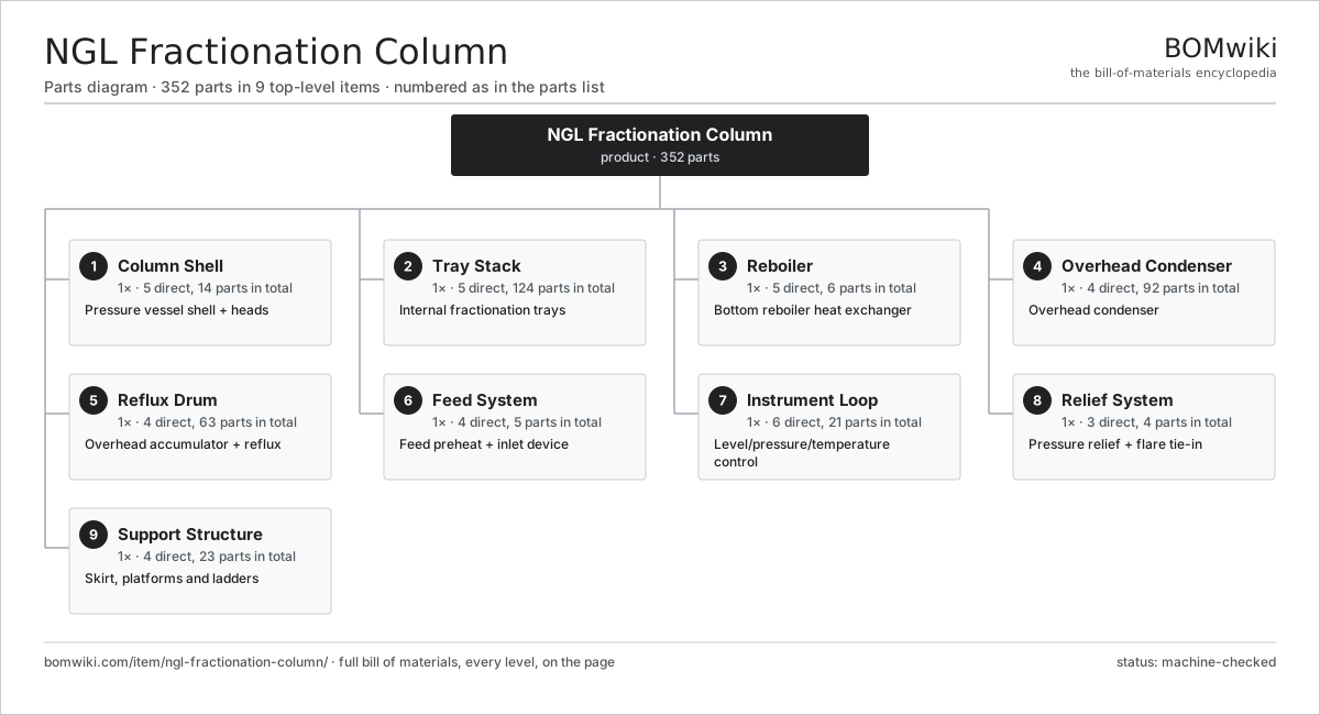
| # | Part | Qty | What it does |
|---|---|---|---|
| 1 | Column Shell 5 parts | 1× | Pressure vessel shell + heads |
| 2 | Tray Stack 5 parts | 1× | Internal fractionation trays |
| 3 | Reboiler 5 parts | 1× | Bottom reboiler heat exchanger |
| 4 | Overhead Condenser 4 parts | 1× | Overhead condenser |
| 5 | Reflux Drum 4 parts | 1× | Overhead accumulator + reflux |
| 6 | Feed System 4 parts | 1× | Feed preheat + inlet device |
| 7 | Instrument Loop 6 parts | 1× | Level/pressure/temperature control |
| 8 | Relief System 3 parts | 1× | Pressure relief + flare tie-in |
| 9 | Support Structure 4 parts | 1× | Skirt, platforms and ladders |
3D model
No 3D model yet. Have a CAD file of this? Add a 3D model. STL renders right on this page; STEP, FreeCAD, and OpenSCAD sources are welcome too (openly licensed, like all 3D models on BOMwiki).
Build & assembly graph
expand / collapse · shared sub-assemblies converge · links to related products · est. labourTap an assembly to expand/collapse · tap a part to open it · use “Open page” for any node · drag to pan, scroll to zoom.
Bill of materials for NGL Fractionation Column
9 top-level lines · 58 rows shown · 352 parts total · indented to 3 levels| # | Item / sub-assembly | Part no. | Qty/assy | Ext. qty | Parts | Type |
|---|---|---|---|---|---|---|
| 1 | Column Shell 5 parts | nfc-column-shell | 1× | 1 | 14 | assembly |
| 1.1 | Shell Course | nfc-shell-course | 6× | 6 | · | part |
| 1.2 | Elliptical Head | nfc-head-elliptical | 2× | 2 | · | part |
| 1.3 | Manway | nfc-manway | 4× | 4 | · | part |
| 1.4 | Nozzle Set | nfc-nozzle-set | 1× | 1 | · | part |
| 1.5 | Insulation & Cladding | nfc-insulation | 1× | 1 | · | part |
| 2 | Tray Stack 5 parts | nfc-tray-stack | 1× | 1 | 124 | assembly |
| 2.1 | Valve Tray | nfc-valve-tray | 30× | 30 | · | part |
| 2.2 | Downcomer | nfc-downcomer | 30× | 30 | · | part |
| 2.3 | Tray Support Ring | nfc-tray-support-ring | 32× | 32 | · | part |
| 2.4 | Outlet Weir | nfc-weir | 30× | 30 | · | part |
| 2.5 | Chimney Tray | nfc-chimney-tray | 2× | 2 | · | part |
| 3 | Reboiler 5 parts | nfc-reboiler | 1× | 1 | 6 | assembly |
| 3.1 | Reboiler Shell | nfc-reboiler-shell | 1× | 1 | · | part |
| 3.2 | Tube Bundle | nfc-tube-bundle | 1× | 1 | · | part |
| 3.3 | Tubesheet | nfc-tubesheet | 1× | 1 | · | part |
| 3.4 | Channel Cover | nfc-channel-cover | 1× | 1 | · | part |
| 3.5 | O-Ring Set | oring-set | 2× | 2 | · | part |
| 4 | Overhead Condenser 4 parts | nfc-overhead-condenser | 1× | 1 | 92 | assembly |
| 4.1 | Finned Tube | nfc-finned-tube | 40× | 40 | · | part |
| 4.2 | Condenser Header | nfc-condenser-header | 2× | 2 | · | part |
| 4.3 | Cooler Fan | nfc-fan | 2× | 2 | · | part |
| 4.4 | Servo Motor 4 parts | servo-motor | 2× | 2 | 24 | assembly |
| 4.4.1 | Stator Assembly 3 parts + deeper › | stator-assembly | 1× | 2 | 3 | assembly |
| 4.4.2 | Rotor Assembly 4 parts + deeper › | rotor-assembly | 1× | 2 | 19 | assembly |
| 4.4.3 | Encoder | encoder | 1× | 2 | · | part |
| 4.4.4 | Motor Housing | motor-housing | 1× | 2 | · | part |
| 5 | Reflux Drum 4 parts | nfc-reflux-drum | 1× | 1 | 63 | assembly |
| 5.1 | Drum Shell | nfc-drum-shell | 1× | 1 | · | part |
| 5.2 | Reflux Pump 5 parts | nfc-reflux-pump | 2× | 2 | 30 | assembly |
| 5.2.1 | Pump Casing | nfc-pump-casing | 1× | 2 | · | part |
| 5.2.2 | Impeller | nfc-impeller | 1× | 2 | · | part |
| 5.2.3 | Ball Bearing | ball-bearing | 2× | 4 | · | part |
| 5.2.4 | Oil Seal | oil-seal | 2× | 4 | · | part |
| 5.2.5 | Servo Motor 4 parts + deeper › | servo-motor | 1× | 2 | 24 | assembly |
| 5.3 | Water Boot | nfc-boot | 1× | 1 | · | part |
| 5.4 | Level Gauge | nfc-level-gauge | 1× | 1 | · | part |
| 6 | Feed System 4 parts | nfc-feed-system | 1× | 1 | 5 | assembly |
| 6.1 | Feed Preheater | nfc-feed-preheater | 1× | 1 | · | part |
| 6.2 | Inlet Distributor | nfc-feed-inlet-device | 1× | 1 | · | part |
| 6.3 | Feed Control Valve | nfc-feed-control-valve | 1× | 1 | · | part |
| 6.4 | Pressure Sensor | pressure-sensor | 2× | 2 | · | part |
| 7 | Instrument Loop 6 parts | nfc-instrument-loop | 1× | 1 | 21 | assembly |
| 7.1 | Pressure Sensor | pressure-sensor | 4× | 4 | · | part |
| 7.2 | Temperature Transmitter | nfc-temp-transmitter | 8× | 8 | · | part |
| 7.3 | Control Valve | nfc-control-valve | 4× | 4 | · | part |
| 7.4 | Online Analyzer | nfc-analyzer | 1× | 1 | · | part |
| 7.5 | Bare PCB | pcb-bare | 2× | 2 | · | part |
| 7.6 | Microcontroller | mcu | 2× | 2 | · | part |
| 8 | Relief System 3 parts | nfc-relief-system | 1× | 1 | 4 | assembly |
| 8.1 | Relief Valve | nfc-relief-valve | 2× | 2 | · | part |
| 8.2 | Rupture Disc | nfc-rupture-disc | 1× | 1 | · | part |
| 8.3 | Flare Header | nfc-flare-header | 1× | 1 | · | part |
| 9 | Support Structure 4 parts | nfc-structure | 1× | 1 | 23 | assembly |
| 9.1 | Support Skirt | nfc-skirt | 1× | 1 | · | part |
| 9.2 | Anchor Bolt | nfc-anchor-bolt | 12× | 12 | · | part |
| 9.3 | Access Platform | nfc-platform | 6× | 6 | · | part |
| 9.4 | Caged Ladder | nfc-ladder | 4× | 4 | · | part |
Related products
same domain, ranked by shared parts Drilling Mud Mixing System
135 parts · shares 13 with this page
Drilling Mud Mixing System
135 parts · shares 13 with this page
 Oilwell Cementing Unit
902 parts · shares 13 with this page
Oilwell Cementing Unit
902 parts · shares 13 with this page
 Shale Shaker
201 parts · shares 13 with this page
Shale Shaker
201 parts · shares 13 with this page
 Sulfur Recovery Unit
206 parts · shares 13 with this page
Sulfur Recovery Unit
206 parts · shares 13 with this page
 Wireline Logging Unit
189 parts · shares 13 with this page
Wireline Logging Unit
189 parts · shares 13 with this page
Sourcing: possible vendors
Browse the supplier directory → Prices, MOQ, and lead times are algorithmic estimates, not quotes, and not claims about these companies. Company mappings are curated by keyword; est. price band $10k–$50M. How estimates work| Vendor | HQ | Specialty | MOQ | Lead time |
|---|---|---|---|---|
|
🇺🇸SLB
slb.com ↗
|
Houston, US | Oilfield services & equipment | made to order | 24–48 wks |
| halliburton.com ↗ | Houston, US | Oilfield services | made to order | 24–48 wks |
| bakerhughes.com ↗ | Houston, US | Energy technology | made to order | 24–48 wks |
|
🇺🇸NOV
nov.com ↗
|
Houston, US | Drilling equipment | made to order | 24–48 wks |
| technipfmc.com ↗ | London, GB | Subsea & surface systems | made to order | 24–48 wks |
874-word article