Marine Drilling Riser Joint
ProductOverview
A marine drilling riser is the large pipe that joins a floating drilling rig at the surface to the blowout preventer and wellhead on the seabed. In deep water that pipe can be two miles long, so it is built from individual sections, each about 75 ft, that the rig screws together one at a time as it runs the riser and unscrews as it pulls it back. The piece described here is one of those sections, a buoyant joint, and it does several jobs at once. The Main Riser Tube carries the drill string and the mud that circulates down the well and back, the Buoyancy Modules keeps the whole string from being unmanageably heavy, and a set of smaller lines strapped to the outside carry the high-pressure and control fluids the subsea stack needs.
Every joint has to make up quickly on a rig floor that is pitching with the sea, hold the tension of everything hanging below it, seal pressure in several bores at once, and survive years of bending as currents and rig motion flex the string. That combination is why a riser joint is a real engineering assembly and not just a length of pipe.
The riser string
Joints stack from the bottom up. At the seabed the riser lands on the lower marine riser package above the BOP; at the top it hangs from the rig through a tensioner system that pulls upward to keep the string straight and stops it buckling under its own weight. The rig adds joints through the rotary table using the Handling & Lift Gear gear, which guides the pin into the box and protects the sealing faces. Because the string is held in tension, the couplings mainly see pull rather than compression, and the design tension capacity, here about 3,500 kips, has to cover the deepest planned water plus a margin for dynamic load when the rig heaves.
Main tube and couplings
The central tube is a 21 in seamless pipe in a high-strength line-pipe steel, with forged ends, the End Forging, welded on to carry the connector. The bore passes the drill string and the drilling fluid, so it is protected by an Internal Wear Liner against abrasion. The connection itself is the Riser Couplings. The upper end is a box and the lower end is a pin; the pin of one joint stabs into the box of the joint below. Tension is carried by a ring of Locking Dog segments that wedge into a groove on the pin, and the two faces are pulled tight by a set of Preload Stud fasteners so the connection never separates under cyclic load. A metal-to-metal Bore Seal keeps drilling fluid pressure inside the main bore. The dog-type design is chosen because it makes up far faster than a threaded connector, which matters when the rig is running hundreds of joints against weather.
Buoyancy modules
Bare steel pipe two miles long would weigh far more than any tensioner could hold, so most of each joint is wrapped in Syntactic Foam Half-Shell modules. These are half-cylinders of syntactic foam, a matrix filled with hollow glass microspheres, that float hard even at full depth because the spheres resist the hydrostatic crush. Two shells clamp around the tube at each band and are held by a Module Clamp and stainless straps. The foam offsets most of the joint weight in water, here up to about 92% of the submerged weight, so the tensioners only have to carry the small net load that is left. The shells are graded by depth, with denser foam lower down where pressure is highest, and the deepest joints sometimes run bare to save cost where the water column above already provides the lift budget.
Choke, kill and auxiliary lines
Strapped around the outside of the tube are the service lines. The Choke & Kill Lines pair are the important ones for well control: if the well kicks and is shut in, the choke line carries returns up to the surface choke and the kill line pumps heavy mud back down, both at up to 15,000 psi. Each has its own bore connector that stabs and seals as the main coupling makes up. The Auxiliary Lines add a booster line and a mud-boost line that keep cuttings moving in the wide riser annulus, and a hydraulic conduit bundle that feeds control pressure to the BOP. All of these lines are held off the tube by the Auxiliary Line Supports arms so they sit at a fixed radius, index correctly to the next joint, and do not chafe or fatigue as the riser flexes.
Materials and loads
The tube and forgings are high-strength low-alloy steels, the forgings to API 2H, selected for toughness at the low temperatures of deep water and for fatigue life under millions of bending cycles. Highly stressed transitions get a corrosion- resistant weld overlay, and the exposed steel between buoyancy modules is coated against seawater. The governing loads are tension from the string weight, bending from current and rig offset, and internal pressure in the several bores. Fatigue, not a single overload, usually sets the design, because the joint near the seabed flex point and near the surface keel sees the most cyclic bending. That is why the Riser Instrumentation reports riser angle and tension live, so the driller can keep each joint inside the envelope it was qualified to.
Variants and deployment
Joints come in lengths, commonly 75 ft with shorter pup joints used to trim the overall string length to the exact water depth. Some joints are slick with no buoyancy for the keel and flex-joint regions, others are fully buoyant for the mid-water span. They are racked vertically or laid out horizontally on deck with Coupling Guard protectors on the sealing faces, then run and retrieved one joint at a time, a slow operation that can take more than a day each way in the deepest water.
Marine Drilling Riser Joint parts and their functions
9 top-level parts · 238 parts in total · full bill of materials below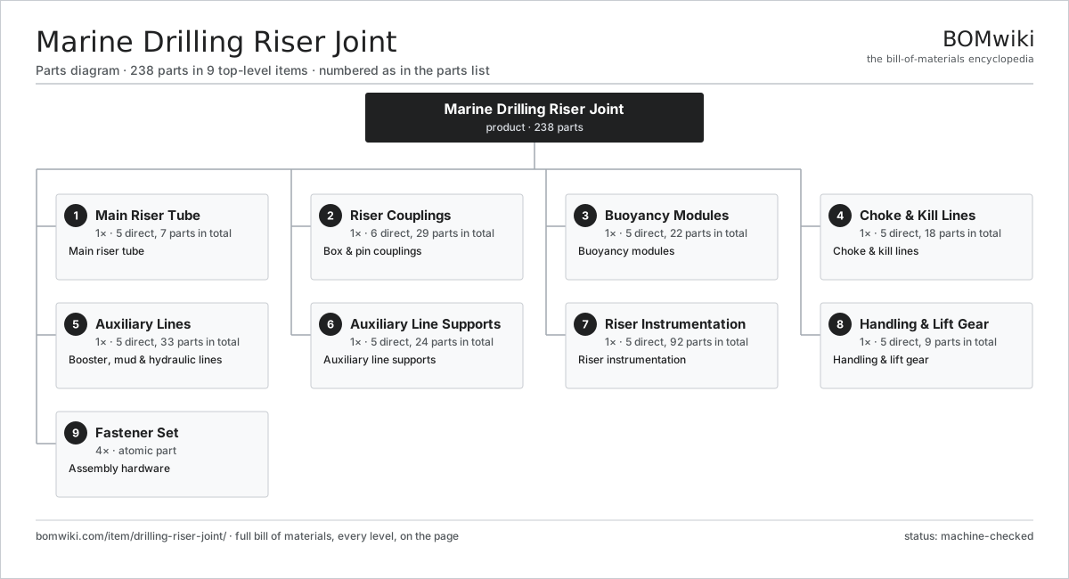
| # | Part | Qty | What it does |
|---|---|---|---|
| 1 | Main Riser Tube 5 parts | 1× | Main riser tube |
| 2 | Riser Couplings 6 parts | 1× | Box & pin couplings |
| 3 | Buoyancy Modules 5 parts | 1× | Buoyancy modules |
| 4 | Choke & Kill Lines 5 parts | 1× | Choke & kill lines |
| 5 | Auxiliary Lines 5 parts | 1× | Booster, mud & hydraulic lines |
| 6 | Auxiliary Line Supports 5 parts | 1× | Auxiliary line supports |
| 7 | Riser Instrumentation 5 parts | 1× | Riser instrumentation |
| 8 | Handling & Lift Gear 5 parts | 1× | Handling & lift gear |
| 9 | Fastener Set | 4× | Assembly hardware |
3D model
No 3D model yet. Have a CAD file of this? Add a 3D model. STL renders right on this page; STEP, FreeCAD, and OpenSCAD sources are welcome too (openly licensed, like all 3D models on BOMwiki).
Build & assembly graph
expand / collapse · shared sub-assemblies converge · links to related products · est. labourTap an assembly to expand/collapse · tap a part to open it · use “Open page” for any node · drag to pan, scroll to zoom.
Bill of materials for Marine Drilling Riser Joint
9 top-level lines · 70 rows shown · 238 parts total · indented to 3 levels| # | Item / sub-assembly | Part no. | Qty/assy | Ext. qty | Parts | Type |
|---|---|---|---|---|---|---|
| 1 | Main Riser Tube 5 parts | drilling-riser-joint-main-tube | 1× | 1 | 7 | assembly |
| 1.1 | Riser Tube Body | drilling-riser-joint-tube-body | 1× | 1 | · | part |
| 1.2 | Internal Wear Liner | drilling-riser-joint-tube-liner | 1× | 1 | · | part |
| 1.3 | End Forging | drilling-riser-joint-end-forging | 2× | 2 | · | part |
| 1.4 | Weld Overlay Band | drilling-riser-joint-weld-overlay | 2× | 2 | · | part |
| 1.5 | External Coating | drilling-riser-joint-tube-coating | 1× | 1 | · | part |
| 2 | Riser Couplings 6 parts | drilling-riser-joint-coupling-set | 1× | 1 | 29 | assembly |
| 2.1 | Box Coupling 4 parts | drilling-riser-joint-box-coupling | 1× | 1 | 5 | assembly |
| 2.1.1 | Box Body | drilling-riser-joint-box-body | 1× | 1 | · | part |
| 2.1.2 | Dog Actuating Ring | drilling-riser-joint-dog-ring | 1× | 1 | · | part |
| 2.1.3 | Bore Seal | drilling-riser-joint-coupling-seal | 1× | 1 | · | part |
| 2.1.4 | O-Ring Set | oring-set | 2× | 2 | · | part |
| 2.2 | Pin Coupling 3 parts | drilling-riser-joint-pin-coupling | 1× | 1 | 4 | assembly |
| 2.2.1 | Pin Body | drilling-riser-joint-pin-body | 1× | 1 | · | part |
| 2.2.2 | Dog Landing Groove | drilling-riser-joint-dog-groove | 1× | 1 | · | part |
| 2.2.3 | O-Ring Set | oring-set | 2× | 2 | · | part |
| 2.3 | Locking Dog | drilling-riser-joint-locking-dog | 8× | 8 | · | part |
| 2.4 | Preload Stud | drilling-riser-joint-preload-stud | 6× | 6 | · | part |
| 2.5 | Bore Seal | drilling-riser-joint-coupling-seal | 2× | 2 | · | part |
| 2.6 | Alignment Pin | drilling-riser-joint-alignment-pin | 4× | 4 | · | part |
| 3 | Buoyancy Modules 5 parts | drilling-riser-joint-buoyancy | 1× | 1 | 22 | assembly |
| 3.1 | Syntactic Foam Half-Shell | drilling-riser-joint-foam-shell | 4× | 4 | · | part |
| 3.2 | Module Clamp | drilling-riser-joint-module-clamp | 4× | 4 | · | part |
| 3.3 | Retaining Strap | drilling-riser-joint-clamp-strap | 8× | 8 | · | part |
| 3.4 | Shell Skin Coating | drilling-riser-joint-shell-coating | 4× | 4 | · | part |
| 3.5 | Fastener Set | fastener-set | 2× | 2 | · | part |
| 4 | Choke & Kill Lines 5 parts | drilling-riser-joint-choke-kill | 1× | 1 | 18 | assembly |
| 4.1 | Choke Line | drilling-riser-joint-choke-line | 1× | 1 | · | part |
| 4.2 | Kill Line | drilling-riser-joint-kill-line | 1× | 1 | · | part |
| 4.3 | Choke/Kill Coupling 3 parts | drilling-riser-joint-ck-coupling | 2× | 2 | 3 | assembly |
| 4.3.1 | Stab Sub | drilling-riser-joint-ck-stab | 1× | 2 | · | part |
| 4.3.2 | Choke/Kill Coupling Seal | drilling-riser-joint-ck-seal | 1× | 2 | · | part |
| 4.3.3 | O-Ring Set | oring-set | 1× | 2 | · | part |
| 4.4 | Choke/Kill Clamp | drilling-riser-joint-ck-clamp | 6× | 6 | · | part |
| 4.5 | Choke/Kill Coupling Seal | drilling-riser-joint-ck-seal | 4× | 4 | · | part |
| 5 | Auxiliary Lines 5 parts | drilling-riser-joint-aux-lines | 1× | 1 | 33 | assembly |
| 5.1 | Booster Line | drilling-riser-joint-booster-line | 1× | 1 | · | part |
| 5.2 | Mud-Boost Line | drilling-riser-joint-mud-boost-line | 1× | 1 | · | part |
| 5.3 | Hydraulic Conduit 3 parts | drilling-riser-joint-hyd-conduit | 1× | 1 | 16 | assembly |
| 5.3.1 | Conduit Tube | drilling-riser-joint-conduit-tube | 4× | 4 | · | part |
| 5.3.2 | Connector | connector | 8× | 8 | · | part |
| 5.3.3 | O-Ring Set | oring-set | 4× | 4 | · | part |
| 5.4 | Auxiliary Coupling 2 parts | drilling-riser-joint-aux-coupling | 3× | 3 | 3 | assembly |
| 5.4.1 | Stab Sub | drilling-riser-joint-ck-stab | 1× | 3 | · | part |
| 5.4.2 | O-Ring Set | oring-set | 2× | 6 | · | part |
| 5.5 | Auxiliary Line Clamp | drilling-riser-joint-aux-clamp | 6× | 6 | · | part |
| 6 | Auxiliary Line Supports 5 parts | drilling-riser-joint-line-support | 1× | 1 | 24 | assembly |
| 6.1 | Peripheral Support Arm | drilling-riser-joint-support-arm | 4× | 4 | · | part |
| 6.2 | Line Bracket | drilling-riser-joint-line-bracket | 8× | 8 | · | part |
| 6.3 | Spacer Ring | drilling-riser-joint-spacer-ring | 2× | 2 | · | part |
| 6.4 | Wear Pad | drilling-riser-joint-wear-pad | 8× | 8 | · | part |
| 6.5 | Fastener Set | fastener-set | 2× | 2 | · | part |
| 7 | Riser Instrumentation 5 parts | drilling-riser-joint-instrumentation | 1× | 1 | 92 | assembly |
| 7.1 | Riser Angle Sensor | drilling-riser-joint-angle-sensor | 1× | 1 | · | part |
| 7.2 | Pressure Sensor | pressure-sensor | 2× | 2 | · | part |
| 7.3 | Tension Strain Gauge | drilling-riser-joint-strain-gauge | 4× | 4 | · | part |
| 7.4 | Subsea Logger 5 parts | drilling-riser-joint-subsea-logger | 1× | 1 | 84 | assembly |
| 7.4.1 | Bare PCB | pcb-bare | 1× | 1 | · | part |
| 7.4.2 | Microcontroller | mcu | 1× | 1 | · | part |
| 7.4.3 | SMD Passive (R/C/L) | smd-passives | 80× | 80 | · | part |
| 7.4.4 | Power Supply | power-supply | 1× | 1 | · | part |
| 7.4.5 | Logger Pressure Housing | drilling-riser-joint-logger-housing | 1× | 1 | · | part |
| 7.5 | Wire Bundle | wire-bundle | 1× | 1 | · | part |
| 8 | Handling & Lift Gear 5 parts | drilling-riser-joint-handling | 1× | 1 | 9 | assembly |
| 8.1 | Lift Sub | drilling-riser-joint-lift-sub | 1× | 1 | · | part |
| 8.2 | Stab Guide Funnel | drilling-riser-joint-guide-funnel | 1× | 1 | · | part |
| 8.3 | Coupling Guard | drilling-riser-joint-coupling-guard | 2× | 2 | · | part |
| 8.4 | Pad Eye | drilling-riser-joint-pad-eye | 4× | 4 | · | part |
| 8.5 | Fastener Set | fastener-set | 1× | 1 | · | part |
| 9 | Fastener Set | fastener-set | 4× | 4 | · | part |
Related products
same domain, ranked by shared parts Amine Gas Sweetening Unit
3,543 parts · shares 2 with this page
Amine Gas Sweetening Unit
3,543 parts · shares 2 with this page
 Centrifugal Gas Compressor
137 parts · shares 2 with this page
CO2 Injection Pump
463 parts · shares 2 with this page
Centrifugal Gas Compressor
137 parts · shares 2 with this page
CO2 Injection Pump
463 parts · shares 2 with this page
 Condensate Stabilizer Column
2,234 parts · shares 2 with this page
Condensate Stabilizer Column
2,234 parts · shares 2 with this page
 Drilling Mud Degasser
154 parts · shares 2 with this page
Drilling Mud Degasser
154 parts · shares 2 with this page
 Gas Flare System
89 parts · shares 2 with this page
Gas Flare System
89 parts · shares 2 with this page
Sourcing: possible vendors
Browse the supplier directory → Prices, MOQ, and lead times are algorithmic estimates, not quotes, and not claims about these companies. Company mappings are curated by keyword; est. price band $10k–$50M. How estimates work| Vendor | HQ | Specialty | MOQ | Lead time |
|---|---|---|---|---|
|
🇺🇸SLB
slb.com ↗
|
Houston, US | Oilfield services & equipment | made to order | 24–48 wks |
| halliburton.com ↗ | Houston, US | Oilfield services | made to order | 24–48 wks |
| bakerhughes.com ↗ | Houston, US | Energy technology | made to order | 24–48 wks |
|
🇺🇸NOV
nov.com ↗
|
Houston, US | Drilling equipment | made to order | 24–48 wks |
| technipfmc.com ↗ | London, GB | Subsea & surface systems | made to order | 24–48 wks |
1,046-word article