LACT Custody Transfer Unit
ProductOverview
A lease automatic custody transfer unit, universally called a LACT unit, is the cash register of an oil lease. It measures crude oil as it leaves a producer's storage tank and enters a pipeline or truck, recording the net standard volume that the buyer pays for. Because money changes hands on the basis of the meter reading, every component is selected for repeatable accuracy and for resistance to the gas, water and sediment that ride along with field crude. A typical skid handles 50 to 5,000 barrels per hour at custody-grade accuracy of plus or minus 0.10 to 0.25 percent.
The skid is a self-contained measurement plant. Crude is drawn from the lease tank, cleaned of solids and entrained gas, boosted to a stable pressure, measured, sampled, checked for water content, and either passed to sale or diverted back to the tank if it is off-specification. A flow computer ties the measurement chain together, applying temperature, pressure and density corrections and printing the transfer ticket. The whole assembly mounts on a single Skid Base and Piping Spool so it can be trucked to a remote location and connected with a handful of flanged joints.
Process flow
Crude enters through a block valve into the Strainer and Air Eliminator. The Basket Strainer traps pipe scale and sand, and the Air Eliminator Vessel lets entrained gas rise and vent, because gas bubbles passing through the meter would register as liquid volume and bias the sale upward. The cleaned, degassed stream reaches the Charge Pump Train, a centrifugal or sliding-vane booster that develops the differential pressure the meter and downstream pipeline require. The pump keeps the crude above its bubble point so it stays single-phase through the measurement section.
From the pump the crude flows into the Custody Meter Run, where the Positive-Displacement Meter or a Coriolis element measures throughput. A RTD Temperature Probe and Pressure Sensor read the conditions at the meter, and a Vibrating-Element Densitometer supplies live density. The BS&W Monitor and Diverter continuously samples water content; if water exceeds the contract limit, the Reject Diverter Valve sends the stream back to the tank through the Valve Manifold rather than to sale. On-spec crude passes the back-pressure valve and leaves the skid toward the pipeline.
Measurement chain
Custody accuracy depends on the meter and on the corrections applied to its raw output. The positive-displacement meter measures actual volume by counting discrete swept chambers as the Measuring Rotor turns; each revolution displaces a known volume and generates pulses through the Pulse Transmitter and Preamp. Coriolis meters instead measure mass directly from the phase shift of a vibrating tube, then convert to volume using the measured density.
Raw indicated volume is not what the buyer pays for. The Fiscal Flow Computer takes the pulses, the temperature, the pressure and the density, then applies API Manual of Petroleum Measurement Standards corrections. Chapter 11.1 volume correction factors reduce the metered volume to a standard 60 degrees F, and pressure correction accounts for crude compressibility. The result is net standard volume, the basis of the financial transaction. The flow computer also drives the Automatic Composite Sampler and logs every batch for audit.
Proving and verification
A meter drifts as parts wear, so its accuracy is checked periodically against a known reference. The Prover Connection provides flanged tie-ins and a Four-Way Diverter Valve so a portable small-volume prover or a pipe prover can be connected on site. During a proving run, a precisely known volume is passed through both the prover and the meter, and the ratio gives a meter factor that the flow computer applies until the next proving. Most custody contracts require proving at fixed intervals or after a set throughput, and the proving records form part of the measurement audit trail.
Sampling and quality
The buyer needs to know not just how much crude was transferred but what it was. The Isokinetic Sample Probe draws a representative cross-section sample, and the Sample Grab Pump grabs a small volume proportional to flow into the Sample Receiver Cylinder. Over a transfer batch this builds a composite that the lab assays for water, sediment, sulfur and gravity. The Capacitance BS&W Probe gives a continuous capacitance reading of water content as a real-time guard, while the composite sample provides the contractual quality record.
Materials and construction
The wetted process path uses carbon-steel piping to ASME B31.4 with raised-face flanges, while the meter internals and sample-contact parts use stainless steel to resist the corrosive brine and hydrogen sulfide common in field crude. The Pump Impeller and meter rotor are cast in stainless grades for erosion resistance. The Mechanical Seal Cartridge on the pump uses a silicon carbide rotating face against a carbon graphite stationary face, a pairing that tolerates the abrasive, low-lubricity service. All electrical equipment is rated for Class I Division 1 hazardous areas, with the field electronics housed in an Explosion-Proof Enclosure.
Operation and maintenance
A LACT unit runs unattended for long stretches, so reliability and clear alarms matter. The operator monitors the Fiscal Flow Computer for flow rate, BS&W, pressure and any divert events. Routine maintenance includes cleaning the Basket Strainer, checking the Mechanical Seal Cartridge for leakage, calibrating the BS&W Analyzer Electronics, and emptying the Sample Receiver Cylinder each batch. The largest single source of measurement dispute is gas carryover, so the air eliminator and back-pressure valve are watched closely. Periodic proving keeps the meter factor current, and the Valve Manifold is exercised to confirm the divert and isolation valves seal.
LACT Custody Transfer Unit parts and their functions
9 top-level parts · 554 parts in total · full bill of materials below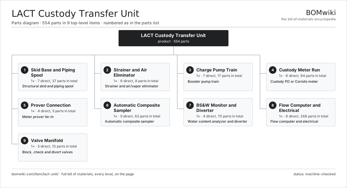
| # | Part | Qty | What it does |
|---|---|---|---|
| 1 | Skid Base and Piping Spool 7 parts | 1× | Structural skid and piping spool |
| 2 | Strainer and Air Eliminator 6 parts | 1× | Strainer and air/vapor eliminator |
| 3 | Charge Pump Train 7 parts | 1× | Booster pump train |
| 4 | Custody Meter Run 6 parts | 1× | Custody PD or Coriolis meter |
| 5 | Prover Connection 4 parts | 1× | Meter prover tie-in |
| 6 | Automatic Composite Sampler 5 parts | 1× | Automatic composite sampler |
| 7 | BS&W Monitor and Diverter 4 parts | 1× | Water content analyzer and diverter |
| 8 | Flow Computer and Electrical 6 parts | 1× | Flow computer and electrical |
| 9 | Valve Manifold 5 parts | 1× | Block, check and divert valves |
3D model
No 3D model yet. Have a CAD file of this? Add a 3D model. STL renders right on this page; STEP, FreeCAD, and OpenSCAD sources are welcome too (openly licensed, like all 3D models on BOMwiki).
Build & assembly graph
expand / collapse · shared sub-assemblies converge · links to related products · est. labourTap an assembly to expand/collapse · tap a part to open it · use “Open page” for any node · drag to pan, scroll to zoom.
Bill of materials for LACT Custody Transfer Unit
9 top-level lines · 109 rows shown · 554 parts total · indented to 3 levels| # | Item / sub-assembly | Part no. | Qty/assy | Ext. qty | Parts | Type |
|---|---|---|---|---|---|---|
| 1 | Skid Base and Piping Spool 7 parts | lact-skid-base | 1× | 1 | 37 | assembly |
| 1.1 | Structural Skid Frame | lact-skid-frame | 1× | 1 | · | part |
| 1.2 | Process Pipe Spool | lact-process-pipe-spool | 1× | 1 | · | part |
| 1.3 | Raised-Face Pipe Flange | lact-pipe-flange | 24× | 24 | · | part |
| 1.4 | Pipe Support Saddle | lact-pipe-support | 8× | 8 | · | part |
| 1.5 | Containment Drip Pan | lact-drip-pan | 1× | 1 | · | part |
| 1.6 | Fastener Set | fastener-set | 1× | 1 | · | part |
| 1.7 | O-Ring Set | oring-set | 1× | 1 | · | part |
| 2 | Strainer and Air Eliminator 6 parts | lact-strainer-eliminator | 1× | 1 | 8 | assembly |
| 2.1 | Basket Strainer 3 parts | lact-basket-strainer | 1× | 1 | 3 | assembly |
| 2.1.1 | Strainer Body | lact-strainer-body | 1× | 1 | · | part |
| 2.1.2 | Stainless Strainer Basket | lact-strainer-basket | 1× | 1 | · | part |
| 2.1.3 | Strainer Cover | lact-strainer-cover | 1× | 1 | · | part |
| 2.2 | Air Eliminator Vessel | lact-air-eliminator-vessel | 1× | 1 | · | part |
| 2.3 | Eliminator Float and Linkage | lact-eliminator-float | 1× | 1 | · | part |
| 2.4 | Gas Vent Valve | lact-vent-valve | 1× | 1 | · | part |
| 2.5 | Pressure Sensor | pressure-sensor | 1× | 1 | · | part |
| 2.6 | O-Ring Set | oring-set | 1× | 1 | · | part |
| 3 | Charge Pump Train 7 parts | lact-charge-pump | 1× | 1 | 17 | assembly |
| 3.1 | Pump Hydraulic End 4 parts | lact-pump-head | 1× | 1 | 5 | assembly |
| 3.1.1 | Pump Casing | lact-pump-casing | 1× | 1 | · | part |
| 3.1.2 | Pump Impeller | lact-pump-impeller | 1× | 1 | · | part |
| 3.1.3 | Casing Wear Ring | lact-wear-ring | 2× | 2 | · | part |
| 3.1.4 | Pump Shaft | lact-pump-shaft | 1× | 1 | · | part |
| 3.2 | TEFC Pump Motor | lact-pump-motor | 1× | 1 | · | part |
| 3.3 | Flexible Coupling | lact-pump-coupling | 1× | 1 | · | part |
| 3.4 | Pump Baseplate | lact-pump-baseplate | 1× | 1 | · | part |
| 3.5 | Mechanical Seal Cartridge 3 parts | mechanical-seal-cartridge | 1× | 1 | 6 | assembly |
| 3.5.1 | Seal Face Set | atu-seal-face-set | 1× | 1 | · | part |
| 3.5.2 | Coil Spring | coil-spring | 4× | 4 | · | part |
| 3.5.3 | O-Ring Set | oring-set | 1× | 1 | · | part |
| 3.6 | Ball Bearing | ball-bearing | 2× | 2 | · | part |
| 3.7 | Pressure Relief Valve | lact-pressure-relief-valve | 1× | 1 | · | part |
| 4 | Custody Meter Run 6 parts | lact-meter-run | 1× | 1 | 94 | assembly |
| 4.1 | Positive-Displacement Meter 5 parts | lact-pd-meter | 1× | 1 | 13 | assembly |
| 4.1.1 | Meter Body | lact-meter-body | 1× | 1 | · | part |
| 4.1.2 | Measuring Rotor | lact-meter-rotor | 1× | 1 | · | part |
| 4.1.3 | Sealing Vane | lact-meter-vanes | 8× | 8 | · | part |
| 4.1.4 | Helical Gear Pair | gear-pair | 1× | 1 | · | part |
| 4.1.5 | Ball Bearing | ball-bearing | 2× | 2 | · | part |
| 4.2 | Pulse Transmitter and Preamp 4 parts | lact-meter-transmitter | 1× | 1 | 44 | assembly |
| 4.2.1 | Bare PCB | pcb-bare | 1× | 1 | · | part |
| 4.2.2 | Microcontroller | mcu | 1× | 1 | · | part |
| 4.2.3 | SMD Passive (R/C/L) | smd-passives | 40× | 40 | · | part |
| 4.2.4 | Connector | connector | 2× | 2 | · | part |
| 4.3 | RTD Temperature Probe | temperature-rtd | 1× | 1 | · | part |
| 4.4 | Pressure Sensor | pressure-sensor | 1× | 1 | · | part |
| 4.5 | Vibrating-Element Densitometer 4 parts | lact-densitometer | 1× | 1 | 33 | assembly |
| 4.5.1 | Bare PCB | pcb-bare | 1× | 1 | · | part |
| 4.5.2 | Microcontroller | mcu | 1× | 1 | · | part |
| 4.5.3 | Piezoelectric Element | piezo-element | 1× | 1 | · | part |
| 4.5.4 | SMD Passive (R/C/L) | smd-passives | 30× | 30 | · | part |
| 4.6 | Double Block-and-Bleed Valve | lact-double-block-bleed | 2× | 2 | · | part |
| 5 | Prover Connection 4 parts | lact-prover-connection | 1× | 1 | 5 | assembly |
| 5.1 | Prover Tie-In Flange | lact-prover-flange | 2× | 2 | · | part |
| 5.2 | Four-Way Diverter Valve | lact-four-way-valve | 1× | 1 | · | part |
| 5.3 | Swing Check Valve | lact-check-valve | 1× | 1 | · | part |
| 5.4 | O-Ring Set | oring-set | 1× | 1 | · | part |
| 6 | Automatic Composite Sampler 5 parts | lact-sampler-system | 1× | 1 | 62 | assembly |
| 6.1 | Isokinetic Sample Probe | lact-sample-probe | 1× | 1 | · | part |
| 6.2 | Sample Grab Pump 4 parts | lact-sample-pump | 1× | 1 | 4 | assembly |
| 6.2.1 | Grab Plunger | lact-sample-plunger | 1× | 1 | · | part |
| 6.2.2 | Coil Spring | coil-spring | 1× | 1 | · | part |
| 6.2.3 | O-Ring Set | oring-set | 1× | 1 | · | part |
| 6.2.4 | Solenoid Actuator | solenoid-actuator | 1× | 1 | · | part |
| 6.3 | Sample Receiver Cylinder | lact-sample-receiver | 1× | 1 | · | part |
| 6.4 | Sampler Controller 4 parts | lact-sample-controller | 1× | 1 | 54 | assembly |
| 6.4.1 | Bare PCB | pcb-bare | 1× | 1 | · | part |
| 6.4.2 | Microcontroller | mcu | 1× | 1 | · | part |
| 6.4.3 | Relay | relay | 2× | 2 | · | part |
| 6.4.4 | SMD Passive (R/C/L) | smd-passives | 50× | 50 | · | part |
| 6.5 | Sample Isolation Valve | lact-isolation-valve | 2× | 2 | · | part |
| 7 | BS&W Monitor and Diverter 4 parts | lact-bsw-monitor | 1× | 1 | 70 | assembly |
| 7.1 | Capacitance BS&W Probe | lact-bsw-probe | 1× | 1 | · | part |
| 7.2 | BS&W Analyzer Electronics 4 parts | lact-bsw-analyzer | 1× | 1 | 63 | assembly |
| 7.2.1 | Bare PCB | pcb-bare | 1× | 1 | · | part |
| 7.2.2 | Microcontroller | mcu | 1× | 1 | · | part |
| 7.2.3 | Analog Front-End IC | afe-ic | 1× | 1 | · | part |
| 7.2.4 | SMD Passive (R/C/L) | smd-passives | 60× | 60 | · | part |
| 7.3 | Reject Diverter Valve 3 parts | lact-divert-valve | 1× | 1 | 5 | assembly |
| 7.3.1 | Valve Body | lact-valve-body | 1× | 1 | · | part |
| 7.3.2 | Valve Actuator 3 parts + deeper › | lact-valve-actuator | 1× | 1 | 3 | assembly |
| 7.3.3 | O-Ring Set | oring-set | 1× | 1 | · | part |
| 7.4 | O-Ring Set | oring-set | 1× | 1 | · | part |
| 8 | Flow Computer and Electrical 6 parts | lact-control-system | 1× | 1 | 248 | assembly |
| 8.1 | Fiscal Flow Computer 5 parts | lact-flow-computer | 1× | 1 | 212 | assembly |
| 8.1.1 | Bare PCB | pcb-bare | 1× | 1 | · | part |
| 8.1.2 | Microcontroller | mcu | 2× | 2 | · | part |
| 8.1.3 | LCD Panel | lcd-panel | 1× | 1 | · | part |
| 8.1.4 | Connector | connector | 8× | 8 | · | part |
| 8.1.5 | SMD Passive (R/C/L) | smd-passives | 200× | 200 | · | part |
| 8.2 | Control Panel 4 parts | lact-control-panel | 1× | 1 | 31 | assembly |
| 8.2.1 | Sheet Metal Panel | sheet-panel | 1× | 1 | · | part |
| 8.2.2 | Relay | relay | 6× | 6 | · | part |
| 8.2.3 | Circuit Breaker | lact-circuit-breaker | 4× | 4 | · | part |
| 8.2.4 | Terminal Block | lact-terminal-block | 20× | 20 | · | part |
| 8.3 | Explosion-Proof Enclosure | lact-explosion-proof-enclosure | 1× | 1 | · | part |
| 8.4 | Power Supply | power-supply | 1× | 1 | · | part |
| 8.5 | Field Junction Box | lact-junction-box | 2× | 2 | · | part |
| 8.6 | Wire Bundle | wire-bundle | 1× | 1 | · | part |
| 9 | Valve Manifold 5 parts | lact-valve-manifold | 1× | 1 | 13 | assembly |
| 9.1 | Block Valve | lact-block-valve | 4× | 4 | · | part |
| 9.2 | Back-Pressure Valve | lact-back-pressure-valve | 1× | 1 | · | part |
| 9.3 | Swing Check Valve | lact-check-valve | 1× | 1 | · | part |
| 9.4 | Valve Actuator 3 parts | lact-valve-actuator | 2× | 2 | 3 | assembly |
| 9.4.1 | Actuator Cylinder | lact-actuator-cylinder | 1× | 2 | · | part |
| 9.4.2 | Coil Spring | coil-spring | 1× | 2 | · | part |
| 9.4.3 | Valve Positioner | lact-actuator-positioner | 1× | 2 | · | part |
| 9.5 | O-Ring Set | oring-set | 1× | 1 | · | part |
Related products
same domain, ranked by shared parts Amine Gas Sweetening Unit
3,543 parts · shares 9 with this page
JT Gas Dew Point Skid
441 parts · shares 9 with this page
TEG Gas Dehydration Skid
587 parts · shares 8 with this page
Amine Gas Sweetening Unit
3,543 parts · shares 9 with this page
JT Gas Dew Point Skid
441 parts · shares 9 with this page
TEG Gas Dehydration Skid
587 parts · shares 8 with this page
 Gas Metering Skid
1,491 parts · shares 7 with this page
Gas Metering Skid
1,491 parts · shares 7 with this page
 Condensate Stabilizer Column
2,234 parts · shares 8 with this page
Condensate Stabilizer Column
2,234 parts · shares 8 with this page
 Wireline Logging Unit
189 parts · shares 7 with this page
Wireline Logging Unit
189 parts · shares 7 with this page
Sourcing: possible vendors
Browse the supplier directory → Prices, MOQ, and lead times are algorithmic estimates, not quotes, and not claims about these companies. Company mappings are curated by keyword; est. price band $10k–$50M. How estimates work| Vendor | HQ | Specialty | MOQ | Lead time |
|---|---|---|---|---|
|
🇺🇸SLB
slb.com ↗
|
Houston, US | Oilfield services & equipment | made to order | 24–48 wks |
| halliburton.com ↗ | Houston, US | Oilfield services | made to order | 24–48 wks |
| bakerhughes.com ↗ | Houston, US | Energy technology | made to order | 24–48 wks |
|
🇺🇸NOV
nov.com ↗
|
Houston, US | Drilling equipment | made to order | 24–48 wks |
| technipfmc.com ↗ | London, GB | Subsea & surface systems | made to order | 24–48 wks |
947-word article