Gas Lift Mandrel and Valve
ProductOverview
A gas lift mandrel and valve is the downhole equipment that makes gas lift work. Many wells stop flowing on their own when reservoir pressure drops too low to push the fluid column to surface. Gas lift restores flow by injecting compressed gas down the casing annulus and into the tubing, where it mixes with the produced liquid. The injected gas reduces the average density of the column, so the same reservoir pressure can lift it. The Side Pocket Mandrel is a tubing sub that carries the Gas Lift Valve in an offset pocket, and the valve is the metering element that admits gas at the right depth and pressure. A string is usually run with several mandrels at increasing depths so the well can be unloaded step by step.
Gas lift valves come in two control philosophies. An injection-pressure-operated (IPO) valve senses casing gas pressure to open, which makes it the common choice for continuous-flow installations. A production-pressure-operated (PPO) valve senses tubing pressure instead, which suits intermittent lift and certain unloading designs. Both types carry a Reverse-Flow Check Valve so that gas only ever moves from casing into tubing.
The side pocket mandrel
The Side Pocket Mandrel solves a geometric problem: the valve has to sit in the flow path of injection gas without blocking the tubing bore. The Mandrel Body is an oval forging that pushes the Side Pocket off to one side, leaving the round through-bore clear for wireline tools, plugs and gauges to pass. The pocket is precision-bored, typically 1 in or 1-1/2 in, and finished with a Polished Bore Receptacle so the valve seals reliably. A Packing Nipple Bore at each end of the pocket gives the valve packing two sealing surfaces, and a cross-drilled Injection Port connects the pocket interior to the casing annulus. Inside the mandrel, the Orienting Sleeve / Discriminator steers the wireline kickover tool toward the pocket mouth. The mandrel runs as part of the string through standard Mandrel Coupling connections.
The nitrogen-charged bellows and dome
The opening pressure of a gas lift valve is set by a gas charge, not by a fixed spring, and that is the function of the Bellows Assembly. A Metal Bellows welded from Monel flexes under the pressure difference between the well and a sealed Dome Charge Chamber above it. The chamber holds a Nitrogen Dome Charge that acts as the reference pressure. Because nitrogen expands with temperature, the charge is set on a test bench and corrected to the temperature at the valve's running depth, so the test-rack opening pressure translates to the correct downhole opening pressure. A Dome Charge Valve core is used to add or bleed nitrogen during setting. To keep the bellows from collapsing under high differential pressure, the assembly includes Bellows Protection in the form of a silicone fill and a backup ring, and a Stem Guide keeps the stem aligned as the bellows strokes.
Stem, ball and seat and the check valve
When the bellows strokes, it drives the Stem, Ball and Seat element. The Valve Stem carries a tungsten-carbide Ball that lifts off the Seat / Port to open the gas passage. The bore of the seat, selected by an interchangeable Port Size Insert, fixes how much gas passes for a given opening, so port sizing is part of the well design. A Coil Spring returns the stem and helps set the closing behaviour. Below the seat sits the Reverse-Flow Check Valve: a Check Dart held on its Check Seat by a Coil Spring inside a Check Cage. The check opens to pass injection gas into the tubing and closes on any reverse pressure, which protects the casing from produced fluid and stops cross-flow when injection stops. The valve seals into the pocket through two Packing Seal Stack seals, each a Chevron Packing set with a Packing Backup Ring ring, all carried in the Valve Body / Housing.
IPO versus PPO operation
An IPO valve is biased so the Metal Bellows mostly sees casing injection pressure. As the operator raises annulus pressure, the casing force overcomes the Nitrogen Dome Charge in the dome, the bellows compresses, and the Ball lifts off the seat. Once gas enters the tubing and lightens the column, the valve is designed to close again at a lower pressure, giving the spread between opening and closing that staged unloading depends on. A PPO valve flips the sensing so tubing pressure dominates, which is used for intermittent lift where slugs of liquid are pushed up on each cycle. In both cases the Reverse-Flow Check Valve enforces one-way flow, and the Port Size Insert sets the throughput.
Installation by wireline kickover tool
The valve is wireline-retrievable, so it can be changed without pulling tubing. A kickover tool run on slickline registers against the mandrel's Kickover Tool Profile: the Orienting Lug swings the tool finger over the pocket, the Locating Groove times the kickover stroke at the right depth, and the Pocket Guide leads the valve packing into the bore. The valve is held in place by the Latch Assembly, whose Latch Collet snaps into the pocket groove under its Latch Spring; a Latch Shear Pin releases it when the pulling tool jars on the Latch Fishing Neck. The valve top carries a Running / Pulling Neck that both the running and pulling tools grip.
Unloading sequence and applications
A new or killed well is full of heavy completion fluid, so it is unloaded one mandrel at a time. Gas injected into the annulus first reaches the shallowest valve, lifts the fluid above it, and lowers the annulus level. As the level drops past each deeper mandrel, that valve takes over and the shallower ones close, transferring the injection point downward until the well lifts from the deepest operating valve. During this sequence a Dummy Valve may occupy mandrels that should stay closed, sealing the Injection Port with the same Packing Seal Stack and Latch Assembly hardware as a live valve. Gas lift suits high-volume wells, deviated and offshore wells, and wells that produce sand or gas that would damage a rod pump, which makes it one of the most widely used forms of artificial lift.
Gas Lift Mandrel and Valve parts and their functions
8 top-level parts · 58 parts in total · full bill of materials below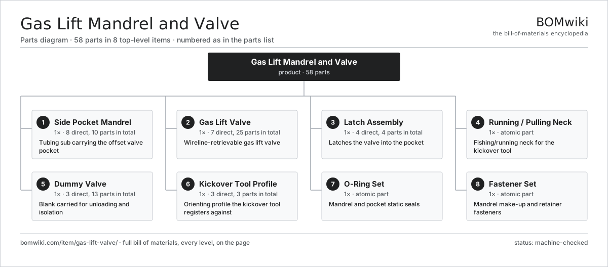
| # | Part | Qty | What it does |
|---|---|---|---|
| 1 | Side Pocket Mandrel 8 parts | 1× | Tubing sub carrying the offset valve pocket |
| 2 | Gas Lift Valve 7 parts | 1× | Wireline-retrievable gas lift valve |
| 3 | Latch Assembly 4 parts | 1× | Latches the valve into the pocket |
| 4 | Running / Pulling Neck | 1× | Fishing/running neck for the kickover tool |
| 5 | Dummy Valve 3 parts | 1× | Blank carried for unloading and isolation |
| 6 | Kickover Tool Profile 3 parts | 1× | Orienting profile the kickover tool registers against |
| 7 | O-Ring Set | 1× | Mandrel and pocket static seals |
| 8 | Fastener Set | 1× | Mandrel make-up and retainer fasteners |
3D model
No 3D model yet. Have a CAD file of this? Add a 3D model. STL renders right on this page; STEP, FreeCAD, and OpenSCAD sources are welcome too (openly licensed, like all 3D models on BOMwiki).
Build & assembly graph
expand / collapse · shared sub-assemblies converge · links to related products · est. labourTap an assembly to expand/collapse · tap a part to open it · use “Open page” for any node · drag to pan, scroll to zoom.
Bill of materials for Gas Lift Mandrel and Valve
8 top-level lines · 57 rows shown · 58 parts total · indented to 3 levels| # | Item / sub-assembly | Part no. | Qty/assy | Ext. qty | Parts | Type |
|---|---|---|---|---|---|---|
| 1 | Side Pocket Mandrel 8 parts | glv-side-pocket-mandrel | 1× | 1 | 10 | assembly |
| 1.1 | Mandrel Body | glv-mandrel-body | 1× | 1 | · | part |
| 1.2 | Side Pocket | glv-side-pocket | 1× | 1 | · | part |
| 1.3 | Orienting Sleeve / Discriminator | glv-orienting-sleeve | 1× | 1 | · | part |
| 1.4 | Polished Bore Receptacle | glv-polished-bore | 1× | 1 | · | part |
| 1.5 | Packing Nipple Bore | glv-packing-nipple-bore | 2× | 2 | · | part |
| 1.6 | Injection Port | glv-injection-port | 1× | 1 | · | part |
| 1.7 | Mandrel Coupling | glv-mandrel-coupling | 2× | 2 | · | part |
| 1.8 | O-Ring Set | oring-set | 1× | 1 | · | part |
| 2 | Gas Lift Valve 7 parts | glv-valve | 1× | 1 | 25 | assembly |
| 2.1 | Valve Body / Housing | glv-valve-body | 1× | 1 | · | part |
| 2.2 | Bellows Assembly 6 parts | glv-bellows-assembly | 1× | 1 | 6 | assembly |
| 2.2.1 | Metal Bellows | glv-metal-bellows | 1× | 1 | · | part |
| 2.2.2 | Dome Charge Chamber | glv-dome-charge-chamber | 1× | 1 | · | part |
| 2.2.3 | Nitrogen Dome Charge | glv-nitrogen-charge | 1× | 1 | · | part |
| 2.2.4 | Bellows Protection | glv-bellows-protection | 1× | 1 | · | part |
| 2.2.5 | Dome Charge Valve | glv-charge-valve | 1× | 1 | · | part |
| 2.2.6 | Stem Guide | glv-stem-guide | 1× | 1 | · | part |
| 2.3 | Stem, Ball and Seat 4 parts | glv-stem-ball-seat | 1× | 1 | 4 | assembly |
| 2.3.1 | Valve Stem | glv-valve-stem | 1× | 1 | · | part |
| 2.3.2 | Ball | glv-ball | 1× | 1 | · | part |
| 2.3.3 | Seat / Port | glv-seat | 1× | 1 | · | part |
| 2.3.4 | Coil Spring | coil-spring | 1× | 1 | · | part |
| 2.4 | Reverse-Flow Check Valve 4 parts | glv-check-valve | 1× | 1 | 4 | assembly |
| 2.4.1 | Check Dart | glv-check-dart | 1× | 1 | · | part |
| 2.4.2 | Check Seat | glv-check-seat | 1× | 1 | · | part |
| 2.4.3 | Coil Spring | coil-spring | 1× | 1 | · | part |
| 2.4.4 | Check Cage | glv-check-cage | 1× | 1 | · | part |
| 2.5 | Packing Seal Stack 3 parts | glv-packing-stack | 2× | 2 | 4 | assembly |
| 2.5.1 | Chevron Packing | glv-chevron-packing | 1× | 2 | · | part |
| 2.5.2 | Packing Backup Ring | glv-packing-backup | 2× | 4 | · | part |
| 2.5.3 | O-Ring Set | oring-set | 1× | 2 | · | part |
| 2.6 | Port Size Insert | glv-valve-port-insert | 1× | 1 | · | part |
| 2.7 | O-Ring Set | oring-set | 1× | 1 | · | part |
| 3 | Latch Assembly 4 parts | glv-latch | 1× | 1 | 4 | assembly |
| 3.1 | Latch Collet | glv-latch-collet | 1× | 1 | · | part |
| 3.2 | Latch Spring | glv-latch-spring | 1× | 1 | · | part |
| 3.3 | Latch Shear Pin | glv-latch-shear-pin | 1× | 1 | · | part |
| 3.4 | Latch Fishing Neck | glv-latch-fishing-neck | 1× | 1 | · | part |
| 4 | Running / Pulling Neck | glv-running-neck | 1× | 1 | · | part |
| 5 | Dummy Valve 3 parts | glv-dummy-valve | 1× | 1 | 13 | assembly |
| 5.1 | Dummy Valve Body | glv-dummy-body | 1× | 1 | · | part |
| 5.2 | Packing Seal Stack 3 parts | glv-packing-stack | 2× | 2 | 4 | assembly |
| 5.2.1 | Chevron Packing | glv-chevron-packing | 1× | 2 | · | part |
| 5.2.2 | Packing Backup Ring | glv-packing-backup | 2× | 4 | · | part |
| 5.2.3 | O-Ring Set | oring-set | 1× | 2 | · | part |
| 5.3 | Latch Assembly 4 parts | glv-latch | 1× | 1 | 4 | assembly |
| 5.3.1 | Latch Collet | glv-latch-collet | 1× | 1 | · | part |
| 5.3.2 | Latch Spring | glv-latch-spring | 1× | 1 | · | part |
| 5.3.3 | Latch Shear Pin | glv-latch-shear-pin | 1× | 1 | · | part |
| 5.3.4 | Latch Fishing Neck | glv-latch-fishing-neck | 1× | 1 | · | part |
| 6 | Kickover Tool Profile 3 parts | glv-kickover-profile | 1× | 1 | 3 | assembly |
| 6.1 | Orienting Lug | glv-orienting-lug | 1× | 1 | · | part |
| 6.2 | Locating Groove | glv-locating-groove | 1× | 1 | · | part |
| 6.3 | Pocket Guide | glv-pocket-guide | 1× | 1 | · | part |
| 7 | O-Ring Set | oring-set | 1× | 1 | · | part |
| 8 | Fastener Set | fastener-set | 1× | 1 | · | part |
Related products
same domain, ranked by shared parts Amine Gas Sweetening Unit
3,543 parts · shares 1 with this page
Amine Gas Sweetening Unit
3,543 parts · shares 1 with this page
 Condensate Stabilizer Column
2,234 parts · shares 1 with this page
Downhole Production Packer
83 parts · shares 1 with this page
Condensate Stabilizer Column
2,234 parts · shares 1 with this page
Downhole Production Packer
83 parts · shares 1 with this page
 Floating-Roof Storage Tank
144 parts · shares 1 with this page
Floating-Roof Storage Tank
144 parts · shares 1 with this page
 Gas Metering Skid
1,491 parts · shares 1 with this page
Gas Metering Skid
1,491 parts · shares 1 with this page
 Gas Pressure Regulating Station
133 parts · shares 1 with this page
Gas Pressure Regulating Station
133 parts · shares 1 with this page
Sourcing: possible vendors
Browse the supplier directory → Prices, MOQ, and lead times are algorithmic estimates, not quotes, and not claims about these companies. Company mappings are curated by keyword; est. price band $10k–$50M. How estimates work| Vendor | HQ | Specialty | MOQ | Lead time |
|---|---|---|---|---|
|
🇺🇸SLB
slb.com ↗
|
Houston, US | Oilfield services & equipment | made to order | 24–48 wks |
| halliburton.com ↗ | Houston, US | Oilfield services | made to order | 24–48 wks |
| bakerhughes.com ↗ | Houston, US | Energy technology | made to order | 24–48 wks |
|
🇺🇸NOV
nov.com ↗
|
Houston, US | Drilling equipment | made to order | 24–48 wks |
| technipfmc.com ↗ | London, GB | Subsea & surface systems | made to order | 24–48 wks |
1,075-word article