Crude Oil Desalter
ProductOverview
A crude oil desalter removes inorganic salts, suspended sediment and residual water from crude oil before it enters the refinery's atmospheric distillation unit. Crude arrives at a refinery carrying dissolved salts, mainly sodium, calcium and magnesium chlorides, that are held in tiny water droplets emulsified in the oil. If those salts reach the distillation columns, they hydrolyze under heat to form hydrochloric acid, which corrodes the overhead piping and condensers, and they deposit scale that fouls heat exchangers and furnace tubes. The desalter cuts the salt content from as much as 200 pounds per thousand barrels at the inlet to under 1 pound per thousand barrels at the outlet.
The desalter works by washing and electrostatic coalescence. Fresh wash water is mixed into the crude to dissolve the salts out of the natural brine droplets, then a high-voltage electric field merges those small water droplets into large ones that settle out by gravity. The Pressure Vessel holds the crude at refinery preheat temperature, around 230 to 300 degrees Fahrenheit, which lowers the oil viscosity and speeds the settling of the water.
Wash water and mixing
The first step is dilution. The Wash Water System system injects fresh water, typically 4 to 10 percent of the crude volume, and an adjustable mixing valve disperses it into the oil as fine droplets. The mixing valve controls shear carefully: too little mixing leaves the wash water unable to reach the salt-bearing brine, while too much mixing creates a tight emulsion that is hard to break later. An inline static mixer completes the dispersion, and a flow meter sets the water rate. The fresh wash water dilutes the salt concentration in the combined water phase, so when the water is later removed it carries the salt with it.
Electrostatic coalescence
Inside the vessel, the diluted crude rises through the Electrostatic Grid, a set of horizontal electrode plates energized to between 12,000 and 35,000 volts. The electric field polarizes the dispersed water droplets, lining up their charges so that neighboring droplets attract one another and merge. As droplets coalesce they grow heavy enough to fall out of the rising oil and settle into the brine layer at the bottom of the vessel. The electrodes are suspended on ceramic standoff insulators and fed through sealed power entrance bushings in the shell, and the vessel itself is bonded to ground so the field exists only between the energized grid and the conductive brine layer below.
Power for the grid comes from the High-Voltage Transformer, an oil-filled step-up transformer with a series reactor. The reactor is essential: when conductive water bridges the electrodes it would otherwise draw a large fault current, so the reactor limits that current and lets the field re-establish itself once the bridge clears. A tap changer adjusts the voltage to match the crude's conductivity and emulsion tendency, and a current monitor watches for sustained arcing that signals a high interface or a process upset.
Internal flow distribution
Even distribution under the electrodes is critical, because any channeling lets unwashed crude bypass the field. The Distribution Internals internals include a perforated inlet header and spreader plates that lay the flow out flat below the grid, a top collector that gathers the desalted oil, and a bottom collector that draws off the brine. A mud wash header along the bottom periodically fluidizes and flushes the settled sediment and solids that otherwise build up and short out the grid.
Interface control and safety
Holding the oil-brine interface at the right height keeps the brine well below the electrodes. If the interface rises into the grid, the conductive water shorts the field and the desalter stops working. The Control System system uses an interface transmitter to find the boundary and modulates the brine outlet valve to hold it steady, with sight glasses and level switches as backup. Electrical interlocks shut off the transformer if the interface gets too high or a door is opened. The Pressure and Relief train protects the heated vessel from overpressure with an ASME relief valve and a backup rupture disc, and pressure transmitters feed the plant safety system.
Variants and use
Single-stage desalters reach the salt targets for light, low-salt crudes, while two-stage units run two vessels in series with counter-current wash water for heavy or high-salt crudes, achieving deeper salt removal with less water. AC fields are standard, though dual-frequency AC and DC fields are used for difficult emulsions. The desalter sits in the crude preheat train ahead of the atmospheric column, often downstream of upstream water removal in a Free Water Knockout Drum, and it is the refinery's main defense against chloride corrosion and exchanger fouling.
Crude Oil Desalter parts and their functions
8 top-level parts · 86 parts in total · full bill of materials below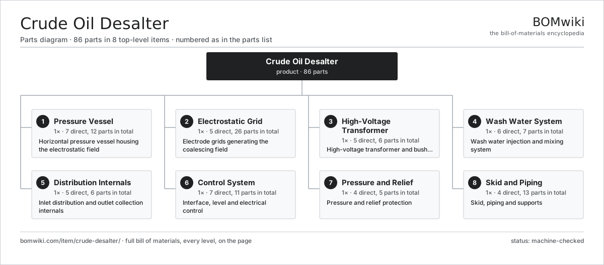
| # | Part | Qty | What it does |
|---|---|---|---|
| 1 | Pressure Vessel 7 parts | 1× | Horizontal pressure vessel housing the electrostatic field |
| 2 | Electrostatic Grid 5 parts | 1× | Electrode grids generating the coalescing field |
| 3 | High-Voltage Transformer 5 parts | 1× | High-voltage transformer and bushings |
| 4 | Wash Water System 6 parts | 1× | Wash water injection and mixing system |
| 5 | Distribution Internals 5 parts | 1× | Inlet distribution and outlet collection internals |
| 6 | Control System 7 parts | 1× | Interface, level and electrical control |
| 7 | Pressure and Relief 4 parts | 1× | Pressure and relief protection |
| 8 | Skid and Piping 4 parts | 1× | Skid, piping and supports |
3D model
No 3D model yet. Have a CAD file of this? Add a 3D model. STL renders right on this page; STEP, FreeCAD, and OpenSCAD sources are welcome too (openly licensed, like all 3D models on BOMwiki).
Build & assembly graph
expand / collapse · shared sub-assemblies converge · links to related products · est. labourTap an assembly to expand/collapse · tap a part to open it · use “Open page” for any node · drag to pan, scroll to zoom.
Bill of materials for Crude Oil Desalter
8 top-level lines · 51 rows shown · 86 parts total · indented to 3 levels| # | Item / sub-assembly | Part no. | Qty/assy | Ext. qty | Parts | Type |
|---|---|---|---|---|---|---|
| 1 | Pressure Vessel 7 parts | crude-desalter-vessel | 1× | 1 | 12 | assembly |
| 1.1 | Shell Course Ring | crude-desalter-shell | 3× | 3 | · | part |
| 1.2 | Vessel Head | crude-desalter-head | 2× | 2 | · | part |
| 1.3 | Nozzle Set | crude-desalter-nozzle-set | 1× | 1 | · | part |
| 1.4 | Saddle Support | crude-desalter-saddle | 2× | 2 | · | part |
| 1.5 | Manway | crude-desalter-manway | 2× | 2 | · | part |
| 1.6 | Thermal Insulation | crude-desalter-insulation | 1× | 1 | · | part |
| 1.7 | Fastener Set | fastener-set | 1× | 1 | · | part |
| 2 | Electrostatic Grid 5 parts | crude-desalter-electrostatic-grid | 1× | 1 | 26 | assembly |
| 2.1 | Electrode Plate | crude-desalter-electrode-plate | 4× | 4 | · | part |
| 2.2 | Grid Hanger | crude-desalter-grid-hanger | 8× | 8 | · | part |
| 2.3 | Standoff Insulator | crude-desalter-insulator | 8× | 8 | · | part |
| 2.4 | Power Entrance Bushing | crude-desalter-entrance-bushing | 2× | 2 | · | part |
| 2.5 | Ground Strap | crude-desalter-ground-strap | 4× | 4 | · | part |
| 3 | High-Voltage Transformer 5 parts | crude-desalter-transformer | 1× | 1 | 6 | assembly |
| 3.1 | Transformer Core | crude-desalter-transformer-core | 1× | 1 | · | part |
| 3.2 | Reactance Coil | crude-desalter-reactance-coil | 1× | 1 | · | part |
| 3.3 | High-Voltage Bushing | crude-desalter-hv-bushing | 2× | 2 | · | part |
| 3.4 | Tap Changer | crude-desalter-tap-changer | 1× | 1 | · | part |
| 3.5 | Transformer Tank | crude-desalter-transformer-tank | 1× | 1 | · | part |
| 4 | Wash Water System 6 parts | crude-desalter-wash-water | 1× | 1 | 7 | assembly |
| 4.1 | Wash Water Pump | crude-desalter-injection-pump | 1× | 1 | · | part |
| 4.2 | Mixing Valve | crude-desalter-mixing-valve | 1× | 1 | · | part |
| 4.3 | Static Mixer | crude-desalter-static-mixer | 1× | 1 | · | part |
| 4.4 | Wash Water Flow Meter | crude-desalter-water-flowmeter | 1× | 1 | · | part |
| 4.5 | Ball Bearing | ball-bearing | 2× | 2 | · | part |
| 4.6 | O-Ring Set | oring-set | 1× | 1 | · | part |
| 5 | Distribution Internals 5 parts | crude-desalter-distribution | 1× | 1 | 6 | assembly |
| 5.1 | Inlet Distribution Header | crude-desalter-inlet-header | 1× | 1 | · | part |
| 5.2 | Spreader Plate | crude-desalter-spreader | 2× | 2 | · | part |
| 5.3 | Oil Collector Header | crude-desalter-oil-collector | 1× | 1 | · | part |
| 5.4 | Brine Collector Header | crude-desalter-water-collector | 1× | 1 | · | part |
| 5.5 | Mud Wash Header | crude-desalter-mud-wash | 1× | 1 | · | part |
| 6 | Control System 7 parts | crude-desalter-control | 1× | 1 | 11 | assembly |
| 6.1 | Interface Transmitter | crude-desalter-interface-transmitter | 1× | 1 | · | part |
| 6.2 | Brine Outlet Valve | crude-desalter-brine-valve | 1× | 1 | · | part |
| 6.3 | Interface Controller | crude-desalter-controller | 1× | 1 | · | part |
| 6.4 | Grid Current Monitor | crude-desalter-current-monitor | 1× | 1 | · | part |
| 6.5 | Sight Glass | crude-desalter-sight-glass | 2× | 2 | · | part |
| 6.6 | Relay | relay | 3× | 3 | · | part |
| 6.7 | Level Switch | crude-desalter-level-switch | 2× | 2 | · | part |
| 7 | Pressure and Relief 4 parts | crude-desalter-relief | 1× | 1 | 5 | assembly |
| 7.1 | Relief Valve | crude-desalter-relief-valve | 1× | 1 | · | part |
| 7.2 | Rupture Disc | crude-desalter-rupture-disc | 1× | 1 | · | part |
| 7.3 | Pressure Sensor | pressure-sensor | 2× | 2 | · | part |
| 7.4 | Vent Valve | crude-desalter-vent-valve | 1× | 1 | · | part |
| 8 | Skid and Piping 4 parts | crude-desalter-skid | 1× | 1 | 13 | assembly |
| 8.1 | Skid Frame | crude-desalter-skid-frame | 1× | 1 | · | part |
| 8.2 | Pipe Spool | crude-desalter-pipe-spool | 5× | 5 | · | part |
| 8.3 | Pipe Support | crude-desalter-pipe-support | 6× | 6 | · | part |
| 8.4 | Walkway and Ladder | crude-desalter-walkway | 1× | 1 | · | part |
Related products
same domain, ranked by shared parts Amine Gas Sweetening Unit
3,543 parts · shares 1 with this page
CO2 Injection Pump
463 parts · shares 1 with this page
Amine Gas Sweetening Unit
3,543 parts · shares 1 with this page
CO2 Injection Pump
463 parts · shares 1 with this page
 Coiled Tubing Unit
190 parts · shares 1 with this page
Coiled Tubing Unit
190 parts · shares 1 with this page
 Condensate Stabilizer Column
2,234 parts · shares 1 with this page
Condensate Stabilizer Column
2,234 parts · shares 1 with this page
 Deepwater Drillship
891,301 parts · shares 1 with this page
Deepwater Drillship
891,301 parts · shares 1 with this page
 Delayed Coker Drum
208 parts · shares 1 with this page
Delayed Coker Drum
208 parts · shares 1 with this page
Sourcing: possible vendors
Browse the supplier directory → Prices, MOQ, and lead times are algorithmic estimates, not quotes, and not claims about these companies. Company mappings are curated by keyword; est. price band $10k–$50M. How estimates work| Vendor | HQ | Specialty | MOQ | Lead time |
|---|---|---|---|---|
|
🇺🇸SLB
slb.com ↗
|
Houston, US | Oilfield services & equipment | made to order | 24–48 wks |
| halliburton.com ↗ | Houston, US | Oilfield services | made to order | 24–48 wks |
| bakerhughes.com ↗ | Houston, US | Energy technology | made to order | 24–48 wks |
|
🇺🇸NOV
nov.com ↗
|
Houston, US | Drilling equipment | made to order | 24–48 wks |
| technipfmc.com ↗ | London, GB | Subsea & surface systems | made to order | 24–48 wks |
799-word article