Side-Entry Tank Mixer
ProductOverview
A side-entry tank mixer is a propeller agitator bolted through the lower wall of a large storage tank to keep the contents moving. In crude oil service it does two jobs: it blends incoming and stored crude so the tank holds one uniform composition, and it keeps water and solids in suspension so they do not settle into a sludge layer on the floor. Crude carries water and sediment, reported together as basic sediment and water (BS&W); if that drops out and consolidates, it reduces usable capacity, fouls heaters and pumps, and forces expensive manual tank cleaning. A mixer running on a duty cycle resuspends those solids before they harden.
The unit mounts low on the Mounting Flange flange so the Propeller Assembly sits near the floor where settling happens. Compared with a top-entry agitator, a side-entry mixer puts the entire drivetrain outside the tank at grade, which makes the motor, reducer, and seal easy to reach for maintenance without confined-space entry. Large tanks use two to four mixers spaced around the shell so their jets cover the whole floor.
How it works
A Drive Motor, typically a 4-pole induction motor running near 1,480 or 1,780 rpm, drives a Gear Reducer that reduces speed to roughly 230 to 420 rpm at the propeller. The reducer output turns the Mixer Shaft through a flexible Drive Coupling, and the shaft carries the propeller in a cantilever into the tank. The Bearing Housing reacts the shaft weight on its radial bearings and the propeller thrust on a dedicated Thrust Bearing.
The propeller is a 3-blade hydrofoil sized for high axial flow at low power. Side-entry mixing is a momentum process: the propeller throws a high-velocity jet across the tank floor, and that jet entrains the surrounding liquid and sets up a slow circulation that turns over the whole tank. The mixer is aimed off the tank centerline using the Swivel Ring, usually 7 to 10 degrees off center, so the jet sweeps the floor in a rotating pattern rather than dead-heading on the far wall.
Subsystems
The shaft penetration is the critical sealing point, because product is held at the tank static head and the shaft turns continuously. The Shaft Seal Assembly uses a cartridge mechanical seal with a Seal Face Pair pair, commonly silicon carbide against carbon, kept cool and clean by a Seal Flush Connection line. A hardened Shaft Sleeve protects the shaft at the seal running surface and is replaced with the seal. A Shutoff Quill Valve shutoff lets the seal be isolated and changed while the tank stays full, which avoids draining a large tank for routine seal service.
The Control and Monitoring handle starting through a Motor Starter and protect the machine with Vibration Sensor accelerometers on the bearing housing plus seal flush pressure monitoring. Loss of flush pressure or rising vibration trips the motor before the seal or bearings fail. The whole drivetrain sits on the Baseframe and Guarding, which aligns the components and carries their weight off the tank nozzle on adjustable legs.
Materials
Wetted parts are selected for the crude and its water and chloride content. Shafts are carbon steel or 316 stainless with a hard-chrome or sleeved running surface at the seal. Propeller blades are cast or fabricated stainless or coated carbon steel. The Gear Reducer is cast iron with case-hardened helical gears running in an extreme-pressure oil charge, and the motor is a flameproof Ex d design for the Zone 1 hazardous area around a hydrocarbon tank.
Variants and applications
Fixed-angle units bolt at one aim direction; swivel-angle units let operators retune the jet after commissioning. Double mechanical seals with a barrier fluid are used where leakage limits are tightest or the product is sour. Motor power ranges from about 7.5 kW on small product tanks to over 100 kW on large crude tanks. Beyond crude blending the same machine suspends solids in fuel oil and asphalt tanks, homogenizes blend components at terminals, and prevents stratification in tanks holding products of differing density. On the largest tanks several mixers run together, sometimes staged on a timer, to turn the inventory over without running all units continuously.
Use and maintenance
Mixers are usually run on a duty cycle rather than continuously: a few hours per day is often enough to keep BS&W in suspension and the tank blended, which saves energy and seal wear. After a long idle period operators ramp the unit carefully, because settled sludge near the Propeller Assembly can shock-load the drivetrain. The Vibration Sensor readings are trended over time, since a slow rise points to bearing wear in the Bearing Housing, propeller fouling, or a bent Mixer Shaft.
Seal life governs most of the maintenance schedule. The Seal Flush Connection keeps the faces clean of abrasive solids, and a drop in Seal Face Pair performance shows up first as leakage at the gland and a fall in flush pressure. When the seal must be replaced, the Shutoff Quill Valve is closed to isolate the shaft penetration, the Drive Coupling is split, and the Seal Cartridge is withdrawn without draining the tank. Gear oil in the Gear Reducer is sampled and changed on a fixed interval, with the Breather and Sight Glass sight glass giving a quick level check between services.
Side-Entry Tank Mixer parts and their functions
10 top-level parts · 165 parts in total · full bill of materials below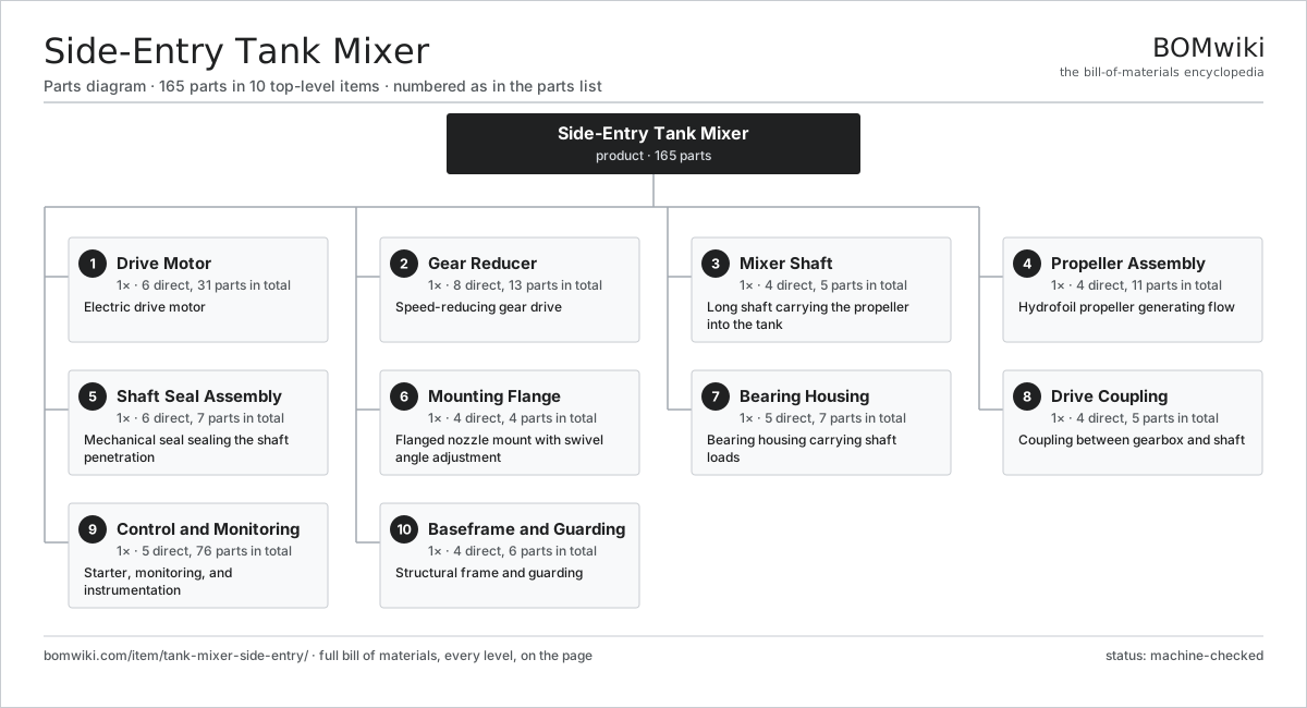
| # | Part | Qty | What it does |
|---|---|---|---|
| 1 | Drive Motor 6 parts | 1× | Electric drive motor |
| 2 | Gear Reducer 8 parts | 1× | Speed-reducing gear drive |
| 3 | Mixer Shaft 4 parts | 1× | Long shaft carrying the propeller into the tank |
| 4 | Propeller Assembly 4 parts | 1× | Hydrofoil propeller generating flow |
| 5 | Shaft Seal Assembly 6 parts | 1× | Mechanical seal sealing the shaft penetration |
| 6 | Mounting Flange 4 parts | 1× | Flanged nozzle mount with swivel angle adjustment |
| 7 | Bearing Housing 5 parts | 1× | Bearing housing carrying shaft loads |
| 8 | Drive Coupling 4 parts | 1× | Coupling between gearbox and shaft |
| 9 | Control and Monitoring 5 parts | 1× | Starter, monitoring, and instrumentation |
| 10 | Baseframe and Guarding 4 parts | 1× | Structural frame and guarding |
3D model
No 3D model yet. Have a CAD file of this? Add a 3D model. STL renders right on this page; STEP, FreeCAD, and OpenSCAD sources are welcome too (openly licensed, like all 3D models on BOMwiki).
Build & assembly graph
expand / collapse · shared sub-assemblies converge · links to related products · est. labourTap an assembly to expand/collapse · tap a part to open it · use “Open page” for any node · drag to pan, scroll to zoom.
Bill of materials for Side-Entry Tank Mixer
10 top-level lines · 74 rows shown · 165 parts total · indented to 3 levels| # | Item / sub-assembly | Part no. | Qty/assy | Ext. qty | Parts | Type |
|---|---|---|---|---|---|---|
| 1 | Drive Motor 6 parts | tank-mixer-side-entry-motor | 1× | 1 | 31 | assembly |
| 1.1 | Stator Assembly 3 parts | stator-assembly | 1× | 1 | 3 | assembly |
| 1.1.1 | Stator Core (laminations) | stator-core | 1× | 1 | · | part |
| 1.1.2 | Copper Winding | copper-winding | 1× | 1 | · | part |
| 1.1.3 | Slot Insulation | stator-insulation | 1× | 1 | · | part |
| 1.2 | Rotor Assembly 4 parts | rotor-assembly | 1× | 1 | 19 | assembly |
| 1.2.1 | Rotor Shaft | rotor-shaft | 1× | 1 | · | part |
| 1.2.2 | Rotor Core | rotor-core | 1× | 1 | · | part |
| 1.2.3 | Neodymium Magnet | neodymium-magnet | 16× | 16 | · | part |
| 1.2.4 | Ball Bearing | ball-bearing | 1× | 1 | · | part |
| 1.3 | Motor Frame | tank-mixer-side-entry-motor-frame | 1× | 1 | · | part |
| 1.4 | Motor Cooling Fan | tank-mixer-side-entry-motor-fan | 1× | 1 | · | part |
| 1.5 | Terminal Box 3 parts | tank-mixer-side-entry-terminal-box | 1× | 1 | 5 | assembly |
| 1.5.1 | Terminal Block | tank-mixer-side-entry-terminal-block | 1× | 1 | · | part |
| 1.5.2 | Connector | connector | 3× | 3 | · | part |
| 1.5.3 | Wire Bundle | wire-bundle | 1× | 1 | · | part |
| 1.6 | Ball Bearing | ball-bearing | 2× | 2 | · | part |
| 2 | Gear Reducer 8 parts | tank-mixer-side-entry-gearbox | 1× | 1 | 13 | assembly |
| 2.1 | Helical Gear Pair | gear-pair | 2× | 2 | · | part |
| 2.2 | Gearbox Housing | gearbox-housing | 1× | 1 | · | part |
| 2.3 | Reducer Input Shaft | tank-mixer-side-entry-input-shaft | 1× | 1 | · | part |
| 2.4 | Reducer Output Shaft | tank-mixer-side-entry-output-shaft | 1× | 1 | · | part |
| 2.5 | Ball Bearing | ball-bearing | 4× | 4 | · | part |
| 2.6 | Oil Seal | oil-seal | 2× | 2 | · | part |
| 2.7 | Gear Oil Charge | tank-mixer-side-entry-gear-oil | 1× | 1 | · | part |
| 2.8 | Breather and Sight Glass | tank-mixer-side-entry-breather | 1× | 1 | · | part |
| 3 | Mixer Shaft 4 parts | tank-mixer-side-entry-shaft | 1× | 1 | 5 | assembly |
| 3.1 | Shaft Barrel | tank-mixer-side-entry-shaft-section | 1× | 1 | · | part |
| 3.2 | Shaft Sleeve | tank-mixer-side-entry-shaft-sleeve | 1× | 1 | · | part |
| 3.3 | Shaft Key | tank-mixer-side-entry-shaft-key | 2× | 2 | · | part |
| 3.4 | Steady Bush | tank-mixer-side-entry-steady-bush | 1× | 1 | · | part |
| 4 | Propeller Assembly 4 parts | tank-mixer-side-entry-propeller | 1× | 1 | 11 | assembly |
| 4.1 | Propeller Hub | tank-mixer-side-entry-prop-hub | 1× | 1 | · | part |
| 4.2 | Propeller Blade | tank-mixer-side-entry-prop-blade | 3× | 3 | · | part |
| 4.3 | Blade Bolt | tank-mixer-side-entry-prop-bolt | 6× | 6 | · | part |
| 4.4 | Hub Retaining Nut | tank-mixer-side-entry-prop-nut | 1× | 1 | · | part |
| 5 | Shaft Seal Assembly 6 parts | tank-mixer-side-entry-seal-assembly | 1× | 1 | 7 | assembly |
| 5.1 | Seal Cartridge | tank-mixer-side-entry-seal-cartridge | 1× | 1 | · | part |
| 5.2 | Seal Face Pair | tank-mixer-side-entry-seal-faces | 2× | 2 | · | part |
| 5.3 | Seal Gland Plate | tank-mixer-side-entry-seal-gland | 1× | 1 | · | part |
| 5.4 | Seal Flush Connection | tank-mixer-side-entry-seal-flush | 1× | 1 | · | part |
| 5.5 | Shutoff Quill Valve | tank-mixer-side-entry-quill-valve | 1× | 1 | · | part |
| 5.6 | O-Ring Set | oring-set | 1× | 1 | · | part |
| 6 | Mounting Flange 4 parts | tank-mixer-side-entry-mount | 1× | 1 | 4 | assembly |
| 6.1 | Mounting Flange | tank-mixer-side-entry-mount-flange | 1× | 1 | · | part |
| 6.2 | Swivel Ring | tank-mixer-side-entry-swivel-ring | 1× | 1 | · | part |
| 6.3 | Flange Gasket | tank-mixer-side-entry-mount-gasket | 1× | 1 | · | part |
| 6.4 | Fastener Set | fastener-set | 1× | 1 | · | part |
| 7 | Bearing Housing 5 parts | tank-mixer-side-entry-bearing-housing | 1× | 1 | 7 | assembly |
| 7.1 | Housing Body | tank-mixer-side-entry-housing-body | 1× | 1 | · | part |
| 7.2 | Thrust Bearing | tank-mixer-side-entry-thrust-bearing | 1× | 1 | · | part |
| 7.3 | Ball Bearing | ball-bearing | 2× | 2 | · | part |
| 7.4 | Oil Seal | oil-seal | 2× | 2 | · | part |
| 7.5 | Lubrication Fitting | tank-mixer-side-entry-lube-fitting | 1× | 1 | · | part |
| 8 | Drive Coupling 4 parts | tank-mixer-side-entry-coupling | 1× | 1 | 5 | assembly |
| 8.1 | Coupling Hub | tank-mixer-side-entry-coupling-hub | 2× | 2 | · | part |
| 8.2 | Flexible Element | tank-mixer-side-entry-coupling-element | 1× | 1 | · | part |
| 8.3 | Coupling Guard | tank-mixer-side-entry-coupling-guard | 1× | 1 | · | part |
| 8.4 | Fastener Set | fastener-set | 1× | 1 | · | part |
| 9 | Control and Monitoring 5 parts | tank-mixer-side-entry-controls | 1× | 1 | 76 | assembly |
| 9.1 | Motor Starter | tank-mixer-side-entry-starter | 1× | 1 | · | part |
| 9.2 | Vibration Sensor | tank-mixer-side-entry-vibration-sensor | 2× | 2 | · | part |
| 9.3 | Monitoring Board 4 parts | tank-mixer-side-entry-control-board | 1× | 1 | 68 | assembly |
| 9.3.1 | Bare PCB | pcb-bare | 1× | 1 | · | part |
| 9.3.2 | Microcontroller | mcu | 1× | 1 | · | part |
| 9.3.3 | SMD Passive (R/C/L) | smd-passives | 60× | 60 | · | part |
| 9.3.4 | Connector | connector | 6× | 6 | · | part |
| 9.4 | Relay | relay | 4× | 4 | · | part |
| 9.5 | Pressure Sensor | pressure-sensor | 1× | 1 | · | part |
| 10 | Baseframe and Guarding 4 parts | tank-mixer-side-entry-baseframe | 1× | 1 | 6 | assembly |
| 10.1 | Base Frame | tank-mixer-side-entry-frame | 1× | 1 | · | part |
| 10.2 | Support Leg | tank-mixer-side-entry-support-leg | 2× | 2 | · | part |
| 10.3 | Sheet Metal Panel | sheet-panel | 2× | 2 | · | part |
| 10.4 | Fastener Set | fastener-set | 1× | 1 | · | part |
Related products
same domain, ranked by shared parts Wireline Logging Unit
189 parts · shares 14 with this page
Wireline Logging Unit
189 parts · shares 14 with this page
 Drilling Top Drive
181 parts · shares 12 with this page
Drilling Top Drive
181 parts · shares 12 with this page
 Hydraulic Fracturing Pump
145 parts · shares 12 with this page
Hydraulic Fracturing Pump
145 parts · shares 12 with this page
 Oil Pumpjack
141 parts · shares 12 with this page
Oil Pumpjack
141 parts · shares 12 with this page
 Oilwell Cementing Unit
902 parts · shares 13 with this page
Oilwell Cementing Unit
902 parts · shares 13 with this page
Sourcing: possible vendors
Browse the supplier directory → Prices, MOQ, and lead times are algorithmic estimates, not quotes, and not claims about these companies. Company mappings are curated by keyword; est. price band $10k–$50M. How estimates work| Vendor | HQ | Specialty | MOQ | Lead time |
|---|---|---|---|---|
|
🇺🇸SLB
slb.com ↗
|
Houston, US | Oilfield services & equipment | made to order | 24–48 wks |
| halliburton.com ↗ | Houston, US | Oilfield services | made to order | 24–48 wks |
| bakerhughes.com ↗ | Houston, US | Energy technology | made to order | 24–48 wks |
|
🇺🇸NOV
nov.com ↗
|
Houston, US | Drilling equipment | made to order | 24–48 wks |
| technipfmc.com ↗ | London, GB | Subsea & surface systems | made to order | 24–48 wks |
995-word article