Gas Metering Skid
ProductOverview
A gas metering skid is the measurement point where natural gas changes ownership, at a wellhead, a gathering inlet, a processing plant tailgate or a pipeline interconnect. Unlike a liquid, gas is compressible and its energy content varies with composition, so a gas skid measures three things at once: how much gas flows, the conditions it flows under, and what it is made of. From those it computes a corrected volume at standard conditions and an energy total in million BTU, which is what the contract settles on. A skid handles anywhere from 50 MSCFD at a small lease to 500 MMSCFD at a major interconnect.
The skid mounts everything on a single Skid Base and Piping with parallel meter tubes fed from a common header, so individual runs can be taken out of service for plate changes or proving while the others keep flowing. Two metering technologies dominate. Orifice metering, governed by AGA Report 3, infers flow from the differential pressure across a precisely bored Orifice Plate. Ultrasonic metering, governed by AGA Report 9, times acoustic pulses across the pipe to measure gas velocity directly. Both feed a Fiscal Flow Computer that applies the corrections.
Inlet conditioning
Gas measurement is sensitive to anything riding in the stream. Liquid slugs, compressor oil and pipe scale all bias the reading and can damage the primary element, so the Inlet Conditioning section cleans the gas first. The Filter Separator drops out liquid in a two-stage vessel, coalescing fine mist on its elements and shedding free liquid through an Automatic Liquid Drain. Downstream, a Flow Conditioner Plate removes swirl and flattens the velocity profile.
Flow conditioning matters because both orifice and ultrasonic meters assume a fully developed, symmetric flow profile. A bend, a valve or a tee upstream creates swirl and asymmetry that the meter reads as extra or missing flow. The standards specify minimum straight lengths of pipe upstream and downstream of the primary element, and a flow conditioner plate lets those lengths be shortened while still delivering a clean profile.
Primary metering
The Primary Meter Tube is a precision-bored straight run carrying the primary element. In an orifice run, the gas passes through the bore of the orifice plate, creating a differential pressure that a Multivariable Transmitter reads along with static pressure and temperature. The senior Senior Orifice Fitting is a dual-chamber device that lets the plate be removed and inspected under full line pressure, a routine task because plate wear and edge damage are the main causes of orifice drift.
In an ultrasonic run, the Ultrasonic Meter Spool carries several pairs of Ultrasonic Transducer elements set at angles across the bore. Each pair times a pulse traveling with the flow and against it; the difference in transit time gives the gas velocity along that path, and multiple paths build a profile that the Ultrasonic Meter Electronics integrates into a flow rate. Ultrasonic meters have no pressure drop and no moving parts, which suits high-volume pipeline service.
Composition and energy
Gas is bought and sold by energy, not volume, and energy depends on composition. The Gas Analyzer System runs an on-line Gas Chromatograph that separates the gas on a packed column and quantifies methane, ethane, propane, the heavier hydrocarbons, nitrogen and carbon dioxide. From that composition the flow computer calculates the heating value and the compressibility factor.
Compressibility is the link between actual and standard conditions. Natural gas does not behave as an ideal gas at line pressure, so the Fiscal Flow Computer applies the AGA 8 equation of state, using the measured composition, pressure and temperature, to convert metered conditions to a standard 14.73 psia and 60 degrees F. The Sample Conditioning System system regulates and dries the sample so the chromatograph sees clean gas, and a Carrier Gas Bottle supplies the helium carrier.
Flow computation and control
Each run has its own fiscal Fiscal Flow Computer so a fault on one run does not corrupt another. The computer reads the primary element, the Multivariable Transmitter or ultrasonic electronics, the RTD Temperature Probe and the composition, applies the AGA flow and compressibility equations, and totalizes corrected volume and energy. It logs hourly and daily records to a Data Logger and serves them to the operator through an Remote Terminal Unit.
The Pressure Regulation section holds the metering pressure stable with a working Pressure Regulator and a Monitor Regulator standing by, and protects the skid with a Pressure Relief Valve and a Slam-Shut Valve that trips on overpressure. The Valve Manifold routes flow between runs and isolates a run for maintenance, with Check Valve protection against backflow.
Materials, power and standards
Process piping follows ASME B31.8 for gas transmission, with weld-neck flanges and carbon-steel spools, while wetted instrument parts and the demister use stainless steel against trace hydrogen sulfide and water. All field electrical equipment is rated for Class I hazardous areas, and the analyzer lives in a climate-controlled Analyzer Shelter. Remote sites often run on a Solar Power System system with battery backup, since many metering points sit far from grid power.
The whole skid is built and operated to a stack of standards: AGA 3 and AGA 9 for the primary measurement, AGA 8 for compressibility, API MPMS Chapter 14 for sampling and Chapter 21 for the electronic flow measurement and audit trail. Together they make the skid's numbers defensible in a custody dispute, which is the entire point of fiscal metering.
Gas Metering Skid parts and their functions
8 top-level parts · 1,491 parts in total · full bill of materials below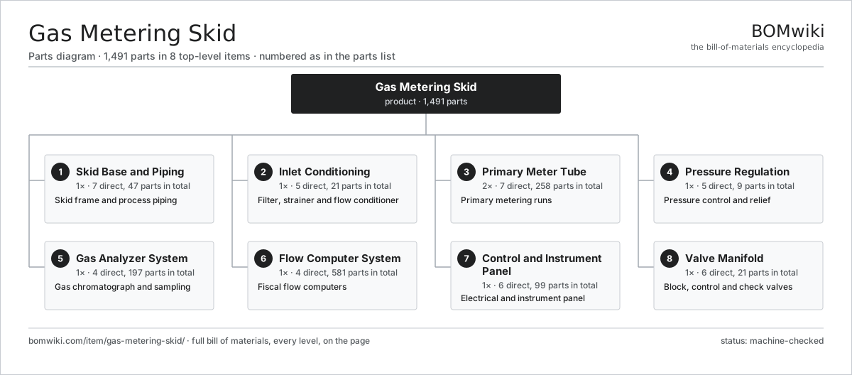
| # | Part | Qty | What it does |
|---|---|---|---|
| 1 | Skid Base and Piping 7 parts | 1× | Skid frame and process piping |
| 2 | Inlet Conditioning 5 parts | 1× | Filter, strainer and flow conditioner |
| 3 | Primary Meter Tube 7 parts | 2× | Primary metering runs |
| 4 | Pressure Regulation 5 parts | 1× | Pressure control and relief |
| 5 | Gas Analyzer System 4 parts | 1× | Gas chromatograph and sampling |
| 6 | Flow Computer System 4 parts | 1× | Fiscal flow computers |
| 7 | Control and Instrument Panel 6 parts | 1× | Electrical and instrument panel |
| 8 | Valve Manifold 6 parts | 1× | Block, control and check valves |
3D model
No 3D model yet. Have a CAD file of this? Add a 3D model. STL renders right on this page; STEP, FreeCAD, and OpenSCAD sources are welcome too (openly licensed, like all 3D models on BOMwiki).
Build & assembly graph
expand / collapse · shared sub-assemblies converge · links to related products · est. labourTap an assembly to expand/collapse · tap a part to open it · use “Open page” for any node · drag to pan, scroll to zoom.
Bill of materials for Gas Metering Skid
8 top-level lines · 104 rows shown · 1,491 parts total · indented to 3 levels| # | Item / sub-assembly | Part no. | Qty/assy | Ext. qty | Parts | Type |
|---|---|---|---|---|---|---|
| 1 | Skid Base and Piping 7 parts | gms-skid-base | 1× | 1 | 47 | assembly |
| 1.1 | Structural Skid Frame | gms-skid-frame | 1× | 1 | · | part |
| 1.2 | Inlet Header | gms-header-inlet | 1× | 1 | · | part |
| 1.3 | Outlet Header | gms-header-outlet | 1× | 1 | · | part |
| 1.4 | Weld-Neck Flange | gms-pipe-flange | 32× | 32 | · | part |
| 1.5 | Pipe Support | gms-pipe-support | 10× | 10 | · | part |
| 1.6 | Fastener Set | fastener-set | 1× | 1 | · | part |
| 1.7 | O-Ring Set | oring-set | 1× | 1 | · | part |
| 2 | Inlet Conditioning 5 parts | gms-inlet-conditioning | 1× | 1 | 21 | assembly |
| 2.1 | Filter Separator 4 parts | gms-filter-separator | 1× | 1 | 11 | assembly |
| 2.1.1 | Separator Vessel | gms-separator-vessel | 1× | 1 | · | part |
| 2.1.2 | Coalescing Filter Element | gms-coalescing-element | 6× | 6 | · | part |
| 2.1.3 | Mist Eliminator Pad | gms-demister-pad | 1× | 1 | · | part |
| 2.1.4 | Automatic Liquid Drain 3 parts + deeper › | gms-liquid-drain | 1× | 1 | 3 | assembly |
| 2.2 | Flow Conditioner Plate | gms-flow-conditioner | 2× | 2 | · | part |
| 2.3 | Coalescing Filter Element | gms-coalescing-element | 4× | 4 | · | part |
| 2.4 | Automatic Liquid Drain 3 parts | gms-liquid-drain | 1× | 1 | 3 | assembly |
| 2.4.1 | Drain Float | gms-drain-float | 1× | 1 | · | part |
| 2.4.2 | Drain Valve | gms-drain-valve | 1× | 1 | · | part |
| 2.4.3 | O-Ring Set | oring-set | 1× | 1 | · | part |
| 2.5 | Pressure Sensor | pressure-sensor | 1× | 1 | · | part |
| 3 | Primary Meter Tube 7 parts | gms-meter-tube | 2× | 2 | 258 | assembly |
| 3.1 | Senior Orifice Fitting 4 parts | gms-orifice-fitting | 1× | 2 | 6 | assembly |
| 3.1.1 | Fitting Body | gms-fitting-body | 1× | 2 | · | part |
| 3.1.2 | Plate Carrier | gms-plate-carrier | 1× | 2 | · | part |
| 3.1.3 | Carrier Drive Gear | gms-shaft-gear | 2× | 4 | · | part |
| 3.1.4 | O-Ring Set | oring-set | 2× | 4 | · | part |
| 3.2 | Orifice Plate | gms-orifice-plate | 1× | 2 | · | part |
| 3.3 | Ultrasonic Meter Spool 3 parts | gms-ultrasonic-spool | 1× | 2 | 184 | assembly |
| 3.3.1 | Meter Spool Body | gms-meter-body | 1× | 2 | · | part |
| 3.3.2 | Ultrasonic Transducer 3 parts + deeper › | gms-transducer | 8× | 16 | 3 | assembly |
| 3.3.3 | Ultrasonic Meter Electronics 4 parts + deeper › | gms-usm-electronics | 1× | 2 | 159 | assembly |
| 3.4 | Honed Tube Spool | gms-tube-spool | 1× | 2 | · | part |
| 3.5 | Multivariable Transmitter 4 parts | gms-multivariable-transmitter | 1× | 2 | 64 | assembly |
| 3.5.1 | Bare PCB | pcb-bare | 1× | 2 | · | part |
| 3.5.2 | Microcontroller | mcu | 1× | 2 | · | part |
| 3.5.3 | Pressure Sensor | pressure-sensor | 2× | 4 | · | part |
| 3.5.4 | SMD Passive (R/C/L) | smd-passives | 60× | 120 | · | part |
| 3.6 | RTD Temperature Probe | temperature-rtd | 1× | 2 | · | part |
| 3.7 | Thermowell | gms-thermowell | 1× | 2 | · | part |
| 4 | Pressure Regulation 5 parts | gms-pressure-regulation | 1× | 1 | 9 | assembly |
| 4.1 | Pressure Regulator 4 parts | gms-pressure-regulator | 1× | 1 | 4 | assembly |
| 4.1.1 | Regulator Body | gms-regulator-body | 1× | 1 | · | part |
| 4.1.2 | Regulator Diaphragm | gms-regulator-diaphragm | 1× | 1 | · | part |
| 4.1.3 | Coil Spring | coil-spring | 1× | 1 | · | part |
| 4.1.4 | Regulator Trim | gms-regulator-trim | 1× | 1 | · | part |
| 4.2 | Monitor Regulator | gms-monitor-regulator | 1× | 1 | · | part |
| 4.3 | Pressure Relief Valve | gms-relief-valve | 1× | 1 | · | part |
| 4.4 | Slam-Shut Valve | gms-slam-shut-valve | 1× | 1 | · | part |
| 4.5 | Pressure Sensor | pressure-sensor | 2× | 2 | · | part |
| 5 | Gas Analyzer System 4 parts | gms-analyzer-system | 1× | 1 | 197 | assembly |
| 5.1 | Gas Chromatograph 5 parts | gms-chromatograph | 1× | 1 | 191 | assembly |
| 5.1.1 | Chromatograph Column | gms-gc-column | 1× | 1 | · | part |
| 5.1.2 | Thermal Conductivity Detector | gms-gc-detector | 1× | 1 | · | part |
| 5.1.3 | Sample Injection Valve | gms-gc-valve | 2× | 2 | · | part |
| 5.1.4 | Column Oven 3 parts + deeper › | gms-gc-oven | 1× | 1 | 3 | assembly |
| 5.1.5 | Chromatograph Controller 4 parts + deeper › | gms-gc-controller | 1× | 1 | 184 | assembly |
| 5.2 | Sample Conditioning System 3 parts | gms-sample-conditioning | 1× | 1 | 4 | assembly |
| 5.2.1 | Sample Regulator | gms-sample-regulator | 1× | 1 | · | part |
| 5.2.2 | Membrane Sample Filter | gms-sample-filter | 2× | 2 | · | part |
| 5.2.3 | Insertion Sample Probe | gms-sample-probe | 1× | 1 | · | part |
| 5.3 | Carrier Gas Bottle | gms-carrier-gas-bottle | 1× | 1 | · | part |
| 5.4 | Analyzer Shelter | gms-analyzer-shelter | 1× | 1 | · | part |
| 6 | Flow Computer System 4 parts | gms-flow-computer-system | 1× | 1 | 581 | assembly |
| 6.1 | Fiscal Flow Computer 5 parts | gms-flow-computer | 2× | 2 | 234 | assembly |
| 6.1.1 | Bare PCB | pcb-bare | 1× | 2 | · | part |
| 6.1.2 | Microcontroller | mcu | 2× | 4 | · | part |
| 6.1.3 | LCD Panel | lcd-panel | 1× | 2 | · | part |
| 6.1.4 | Connector | connector | 10× | 20 | · | part |
| 6.1.5 | SMD Passive (R/C/L) | smd-passives | 220× | 440 | · | part |
| 6.2 | Remote Terminal Unit 4 parts | gms-rtu | 1× | 1 | 100 | assembly |
| 6.2.1 | Bare PCB | pcb-bare | 1× | 1 | · | part |
| 6.2.2 | Microcontroller | mcu | 1× | 1 | · | part |
| 6.2.3 | Connector | connector | 8× | 8 | · | part |
| 6.2.4 | SMD Passive (R/C/L) | smd-passives | 90× | 90 | · | part |
| 6.3 | Data Logger | gms-data-logger | 1× | 1 | · | part |
| 6.4 | Connector | connector | 12× | 12 | · | part |
| 7 | Control and Instrument Panel 6 parts | gms-control-panel | 1× | 1 | 99 | assembly |
| 7.1 | Panel Enclosure 3 parts | gms-panel-enclosure | 1× | 1 | 37 | assembly |
| 7.1.1 | Sheet Metal Panel | sheet-panel | 1× | 1 | · | part |
| 7.1.2 | Terminal Block | gms-terminal-block | 30× | 30 | · | part |
| 7.1.3 | Circuit Breaker | gms-circuit-breaker | 6× | 6 | · | part |
| 7.2 | Power Supply | power-supply | 1× | 1 | · | part |
| 7.3 | Solar Power System 3 parts | gms-solar-power | 1× | 1 | 49 | assembly |
| 7.3.1 | Photovoltaic Panel | gms-solar-panel | 1× | 1 | · | part |
| 7.3.2 | Charge Controller 4 parts + deeper › | gms-charge-controller | 1× | 1 | 46 | assembly |
| 7.3.3 | Sealed Lead-Acid Battery | gms-battery | 2× | 2 | · | part |
| 7.4 | Explosion-Proof Junction Box | gms-junction-box | 3× | 3 | · | part |
| 7.5 | Relay | relay | 8× | 8 | · | part |
| 7.6 | Wire Bundle | wire-bundle | 1× | 1 | · | part |
| 8 | Valve Manifold 6 parts | gms-valve-manifold | 1× | 1 | 21 | assembly |
| 8.1 | Block Valve | gms-block-valve | 4× | 4 | · | part |
| 8.2 | Flow Control Valve 4 parts | gms-control-valve | 1× | 1 | 6 | assembly |
| 8.2.1 | Valve Body | gms-valve-body | 1× | 1 | · | part |
| 8.2.2 | Valve Trim | gms-valve-trim | 1× | 1 | · | part |
| 8.2.3 | Valve Actuator 3 parts + deeper › | gms-valve-actuator | 1× | 1 | 3 | assembly |
| 8.2.4 | O-Ring Set | oring-set | 1× | 1 | · | part |
| 8.3 | Check Valve | gms-check-valve | 2× | 2 | · | part |
| 8.4 | Three-Valve Manifold | gms-three-valve-manifold | 2× | 2 | · | part |
| 8.5 | Valve Actuator 3 parts | gms-valve-actuator | 2× | 2 | 3 | assembly |
| 8.5.1 | Actuator Cylinder | gms-actuator-cylinder | 1× | 2 | · | part |
| 8.5.2 | Coil Spring | coil-spring | 1× | 2 | · | part |
| 8.5.3 | Valve Positioner | gms-positioner | 1× | 2 | · | part |
| 8.6 | O-Ring Set | oring-set | 1× | 1 | · | part |
Related products
same domain, ranked by shared parts Amine Gas Sweetening Unit
3,543 parts · shares 6 with this page
Amine Gas Sweetening Unit
3,543 parts · shares 6 with this page
 Condensate Stabilizer Column
2,234 parts · shares 6 with this page
Condensate Stabilizer Column
2,234 parts · shares 6 with this page
 Gas Pressure Regulating Station
133 parts · shares 6 with this page
Gas Pressure Regulating Station
133 parts · shares 6 with this page
 Wireline Logging Unit
189 parts · shares 6 with this page
JT Gas Dew Point Skid
441 parts · shares 5 with this page
Wireline Logging Unit
189 parts · shares 6 with this page
JT Gas Dew Point Skid
441 parts · shares 5 with this page
Sourcing: possible vendors
Browse the supplier directory → Prices, MOQ, and lead times are algorithmic estimates, not quotes, and not claims about these companies. Company mappings are curated by keyword; est. price band $10k–$50M. How estimates work| Vendor | HQ | Specialty | MOQ | Lead time |
|---|---|---|---|---|
|
🇺🇸SLB
slb.com ↗
|
Houston, US | Oilfield services & equipment | made to order | 24–48 wks |
| halliburton.com ↗ | Houston, US | Oilfield services | made to order | 24–48 wks |
| bakerhughes.com ↗ | Houston, US | Energy technology | made to order | 24–48 wks |
|
🇺🇸NOV
nov.com ↗
|
Houston, US | Drilling equipment | made to order | 24–48 wks |
| technipfmc.com ↗ | London, GB | Subsea & surface systems | made to order | 24–48 wks |
927-word article