TEG Gas Dehydration Skid
ProductOverview
A glycol dehydration skid removes water vapor from natural gas. Gas leaving a separator is saturated with water, and that water causes two problems downstream: it forms solid hydrate plugs that block pipelines and valves, and it combines with acid gases to corrode steel. Sales contracts therefore cap water content at around 4 to 7 pounds per million standard cubic feet. The skid meets that limit by washing the gas with triethylene glycol, a hygroscopic liquid that pulls water vapor out of the gas stream, then regenerating the glycol by boiling the water back off. TEG is the standard solvent because it absorbs water strongly, regenerates to high purity and has low vapor loss.
The skid runs a closed glycol loop between two zones. The high-pressure Glycol Contactor is where dry glycol meets wet gas and absorbs the water. The low-pressure regeneration package, built around the Glycol Reboiler and Stripping Still, boils that water out and returns lean glycol to the contactor. A skid handles 1 to 200 MMSCFD and is built compact enough to truck to a remote pad.
Absorption in the contactor
Wet gas first passes through the Inlet Scrubber, a two-phase separator that drops out free liquid and slugs so the contactor sees only vapor. Carrying free water or hydrocarbon liquid into the contactor would flood the trays and contaminate the glycol, so the scrubber and its Demister Pad are essential protection.
The scrubbed gas enters the bottom of the Glycol Contactor and rises through a stack of Bubble-Cap Tray stages. Lean glycol, pumped to contactor pressure, enters at the top and flows down across each tray. On every tray the gas bubbles up through a held level of glycol behind the Bubble Cap caps, and the glycol absorbs water vapor from the gas. The dried gas leaves the top through a Mist Eliminator that catches glycol droplets, while the now-wet rich glycol collects on the bottom chimney tray and leaves for regeneration. More trays and colder, drier glycol give a deeper dew point depression.
Flashing and heat recovery
Rich glycol leaving the contactor is at high pressure and carries dissolved hydrocarbon gas and some condensed hydrocarbon liquid. It drops into the Flash Separator, a three-phase tank that releases the dissolved gas through a Flash Gas Valve for use as fuel, skims hydrocarbon liquid off the top, and passes the rich glycol on. Removing hydrocarbons here protects the reboiler from foaming and reduces emissions from the still.
The rich glycol then flows through the Glycol Heat Exchange section. The Lean/Rich Glycol Exchanger preheats the cold rich glycol with hot lean glycol returning from the reboiler, recovering heat and reducing the reboiler's fuel use. On the return path the Lean Glycol Cooler drops the lean glycol to within a few degrees of the inlet gas temperature, because glycol fed in too hot would vaporize and be lost overhead with the gas.
Regeneration
The preheated rich glycol enters the Glycol Reboiler, where a U-Tube Firetube fired by the Gas Burner heats the glycol to about 390 to 400 degrees F. Water boils off as vapor while the glycol stays liquid, because TEG boils far higher than water. The temperature is held just below the point where TEG itself begins to decompose, since overheating darkens and degrades the glycol. The water vapor rises into the Stripping Still, a packed still that lets water vapor escape to atmosphere while a Reflux Condenser Coil condenses entrained glycol and refluxes it back, keeping glycol loss low.
To reach the highest lean glycol purity, above about 99 percent, a small flow of dry Stripping Gas Coil gas is sparged through the hot glycol in the reboiler. The stripping gas lowers the partial pressure of water over the glycol and carries off the last traces of water, which is what enables the deepest dew point depressions.
Circulation and solution care
The Glycol Circulation system keeps the loop moving and clean. A high-pressure Glycol Pump lifts lean glycol from the reboiler base back to contactor pressure. Glycol cleanliness controls foaming and heat transfer, so a Sock Filter removes solids and a slipstream through the Activated Carbon Filter adsorbs hydrocarbons and degradation products. The Glycol Surge Drum holds the lean glycol inventory and accommodates the loop's volume swings.
Control and safety
The Control System holds the three variables that set performance: reboiler temperature, glycol circulation rate and contactor level. A Moisture Analyzer confirms the dry gas dew point against the sales spec. Because the reboiler is a fired vessel, a Burner Management System burner management system to NFPA 86 proves the Flame Scanner flame before admitting fuel and trips the Fuel Solenoid Valve on loss of flame, low water level or high temperature. The vessels are protected by Relief Valve devices on the skid.
Materials follow the service. The contactor, scrubber and flash vessels are carbon steel to ASME Section VIII, while the still, firetube, internals and exchanger coils are stainless because hot glycol and the water-rich still environment attack carbon steel. Process piping follows ASME B31.3, and the whole package is sized and rated using GPSA dehydration design practice.
TEG Gas Dehydration Skid parts and their functions
9 top-level parts · 587 parts in total · full bill of materials below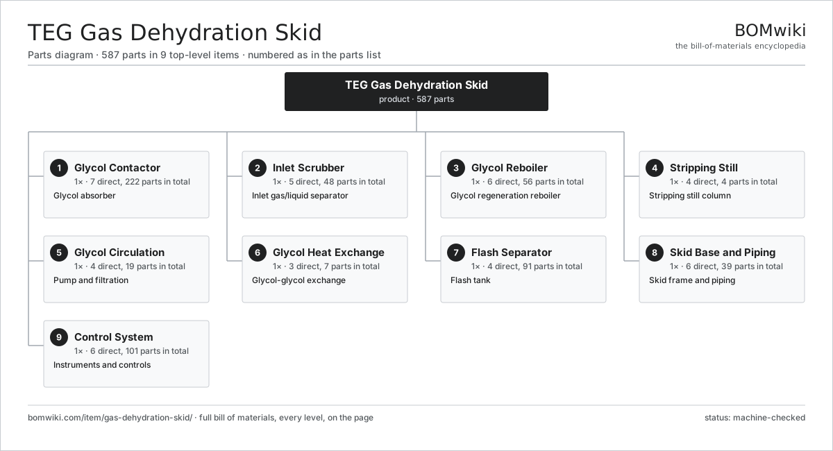
| # | Part | Qty | What it does |
|---|---|---|---|
| 1 | Glycol Contactor 7 parts | 1× | Glycol absorber |
| 2 | Inlet Scrubber 5 parts | 1× | Inlet gas/liquid separator |
| 3 | Glycol Reboiler 6 parts | 1× | Glycol regeneration reboiler |
| 4 | Stripping Still 4 parts | 1× | Stripping still column |
| 5 | Glycol Circulation 4 parts | 1× | Pump and filtration |
| 6 | Glycol Heat Exchange 3 parts | 1× | Glycol-glycol exchange |
| 7 | Flash Separator 4 parts | 1× | Flash tank |
| 8 | Skid Base and Piping 6 parts | 1× | Skid frame and piping |
| 9 | Control System 6 parts | 1× | Instruments and controls |
3D model
No 3D model yet. Have a CAD file of this? Add a 3D model. STL renders right on this page; STEP, FreeCAD, and OpenSCAD sources are welcome too (openly licensed, like all 3D models on BOMwiki).
Build & assembly graph
expand / collapse · shared sub-assemblies converge · links to related products · est. labourTap an assembly to expand/collapse · tap a part to open it · use “Open page” for any node · drag to pan, scroll to zoom.
Bill of materials for TEG Gas Dehydration Skid
9 top-level lines · 92 rows shown · 587 parts total · indented to 3 levels| # | Item / sub-assembly | Part no. | Qty/assy | Ext. qty | Parts | Type |
|---|---|---|---|---|---|---|
| 1 | Glycol Contactor 7 parts | gds-contactor-column | 1× | 1 | 222 | assembly |
| 1.1 | Contactor Shell | gds-contactor-shell | 1× | 1 | · | part |
| 1.2 | Bubble-Cap Tray 3 parts | gds-bubble-tray | 8× | 8 | 26 | assembly |
| 1.2.1 | Tray Deck | gds-tray-deck | 1× | 8 | · | part |
| 1.2.2 | Bubble Cap | gds-bubble-cap | 24× | 192 | · | part |
| 1.2.3 | Downcomer | gds-downcomer | 1× | 8 | · | part |
| 1.3 | Mist Eliminator | gds-mist-eliminator | 1× | 1 | · | part |
| 1.4 | Inlet Gas Distributor | gds-gas-distributor | 1× | 1 | · | part |
| 1.5 | Glycol Chimney Tray | gds-chimney-tray | 1× | 1 | · | part |
| 1.6 | Manway | gds-manway | 2× | 2 | · | part |
| 1.7 | Process Nozzle | gds-nozzle | 8× | 8 | · | part |
| 2 | Inlet Scrubber 5 parts | gds-inlet-scrubber | 1× | 1 | 48 | assembly |
| 2.1 | Scrubber Vessel | gds-scrubber-vessel | 1× | 1 | · | part |
| 2.2 | Demister Pad | gds-demister-pad | 1× | 1 | · | part |
| 2.3 | Inlet Momentum Deflector | gds-inlet-deflector | 1× | 1 | · | part |
| 2.4 | Level Control Loop 2 parts | gds-level-control | 1× | 1 | 44 | assembly |
| 2.4.1 | Level Transmitter 4 parts + deeper › | gds-level-transmitter | 1× | 1 | 43 | assembly |
| 2.4.2 | Level Control Valve | gds-level-valve | 1× | 1 | · | part |
| 2.5 | Liquid Dump Valve | gds-dump-valve | 1× | 1 | · | part |
| 3 | Glycol Reboiler 6 parts | gds-glycol-reboiler | 1× | 1 | 56 | assembly |
| 3.1 | Reboiler Vessel | gds-reboiler-vessel | 1× | 1 | · | part |
| 3.2 | U-Tube Firetube | gds-firetube | 1× | 1 | · | part |
| 3.3 | Gas Burner 4 parts | gds-burner | 1× | 1 | 7 | assembly |
| 3.3.1 | Burner Nozzle | gds-burner-nozzle | 1× | 1 | · | part |
| 3.3.2 | Pilot Assembly | gds-pilot | 1× | 1 | · | part |
| 3.3.3 | Flame Arrestor | gds-flame-arrestor | 1× | 1 | · | part |
| 3.3.4 | Fuel Gas Train 3 parts + deeper › | gds-gas-train | 1× | 1 | 4 | assembly |
| 3.4 | Reboiler Temperature Controller 4 parts | gds-temperature-controller | 1× | 1 | 44 | assembly |
| 3.4.1 | Bare PCB | pcb-bare | 1× | 1 | · | part |
| 3.4.2 | Microcontroller | mcu | 1× | 1 | · | part |
| 3.4.3 | Relay | relay | 2× | 2 | · | part |
| 3.4.4 | SMD Passive (R/C/L) | smd-passives | 40× | 40 | · | part |
| 3.5 | Stripping Gas Coil | gds-stripping-gas-coil | 1× | 1 | · | part |
| 3.6 | RTD Temperature Probe | temperature-rtd | 2× | 2 | · | part |
| 4 | Stripping Still 4 parts | gds-still-column | 1× | 1 | 4 | assembly |
| 4.1 | Still Shell | gds-still-shell | 1× | 1 | · | part |
| 4.2 | Ceramic Saddle Packing | gds-still-packing | 1× | 1 | · | part |
| 4.3 | Reflux Condenser Coil | gds-reflux-coil | 1× | 1 | · | part |
| 4.4 | Still Vent | gds-still-vent | 1× | 1 | · | part |
| 5 | Glycol Circulation 4 parts | gds-glycol-circulation | 1× | 1 | 19 | assembly |
| 5.1 | Glycol Pump 4 parts | gds-glycol-pump | 1× | 1 | 11 | assembly |
| 5.1.1 | Pump Fluid End | gds-pump-head | 1× | 1 | · | part |
| 5.1.2 | Pump Motor | gds-pump-motor | 1× | 1 | · | part |
| 5.1.3 | Pump Plunger | gds-pump-plunger | 3× | 3 | · | part |
| 5.1.4 | Mechanical Seal Cartridge 3 parts + deeper › | mechanical-seal-cartridge | 1× | 1 | 6 | assembly |
| 5.2 | Sock Filter 2 parts | gds-sock-filter | 1× | 1 | 5 | assembly |
| 5.2.1 | Filter Housing | gds-filter-housing | 1× | 1 | · | part |
| 5.2.2 | Filter Sock | gds-filter-sock | 4× | 4 | · | part |
| 5.3 | Activated Carbon Filter 2 parts | gds-carbon-filter | 1× | 1 | 2 | assembly |
| 5.3.1 | Carbon Vessel | gds-carbon-vessel | 1× | 1 | · | part |
| 5.3.2 | Activated Carbon Bed | gds-carbon-bed | 1× | 1 | · | part |
| 5.4 | Glycol Surge Drum | gds-surge-drum | 1× | 1 | · | part |
| 6 | Glycol Heat Exchange 3 parts | gds-heat-exchange | 1× | 1 | 7 | assembly |
| 6.1 | Lean/Rich Glycol Exchanger 3 parts | gds-lean-rich-exchanger | 1× | 1 | 4 | assembly |
| 6.1.1 | Exchanger Shell | gds-exchanger-shell | 1× | 1 | · | part |
| 6.1.2 | Exchanger Coil | gds-exchanger-coil | 1× | 1 | · | part |
| 6.1.3 | Tubesheet | gds-tubesheet | 2× | 2 | · | part |
| 6.2 | Lean Glycol Cooler | gds-glycol-cooler | 1× | 1 | · | part |
| 6.3 | Exchanger Coil | gds-exchanger-coil | 2× | 2 | · | part |
| 7 | Flash Separator 4 parts | gds-flash-separator | 1× | 1 | 91 | assembly |
| 7.1 | Flash Vessel | gds-flash-vessel | 1× | 1 | · | part |
| 7.2 | Hydrocarbon Skimmer | gds-flash-skimmer | 1× | 1 | · | part |
| 7.3 | Flash Gas Valve | gds-flash-gas-valve | 1× | 1 | · | part |
| 7.4 | Level Control Loop 2 parts | gds-level-control | 2× | 2 | 44 | assembly |
| 7.4.1 | Level Transmitter 4 parts + deeper › | gds-level-transmitter | 1× | 2 | 43 | assembly |
| 7.4.2 | Level Control Valve | gds-level-valve | 1× | 2 | · | part |
| 8 | Skid Base and Piping 6 parts | gds-skid-base | 1× | 1 | 39 | assembly |
| 8.1 | Structural Skid Frame | gds-skid-frame | 1× | 1 | · | part |
| 8.2 | Process Pipe Spool | gds-pipe-spool | 1× | 1 | · | part |
| 8.3 | Pipe Flange | gds-pipe-flange | 24× | 24 | · | part |
| 8.4 | Block Valve | gds-block-valve | 10× | 10 | · | part |
| 8.5 | Relief Valve | gds-relief-valve | 2× | 2 | · | part |
| 8.6 | Fastener Set | fastener-set | 1× | 1 | · | part |
| 9 | Control System 6 parts | gds-control-system | 1× | 1 | 101 | assembly |
| 9.1 | Control Panel 4 parts | gds-control-panel | 1× | 1 | 35 | assembly |
| 9.1.1 | Sheet Metal Panel | sheet-panel | 1× | 1 | · | part |
| 9.1.2 | Relay | relay | 6× | 6 | · | part |
| 9.1.3 | Terminal Block | gds-terminal-block | 24× | 24 | · | part |
| 9.1.4 | Circuit Breaker | gds-circuit-breaker | 4× | 4 | · | part |
| 9.2 | Moisture Analyzer 4 parts | gds-moisture-analyzer | 1× | 1 | 53 | assembly |
| 9.2.1 | Bare PCB | pcb-bare | 1× | 1 | · | part |
| 9.2.2 | Microcontroller | mcu | 1× | 1 | · | part |
| 9.2.3 | Analog Front-End IC | afe-ic | 1× | 1 | · | part |
| 9.2.4 | SMD Passive (R/C/L) | smd-passives | 50× | 50 | · | part |
| 9.3 | Burner Management System 4 parts | gds-bms | 1× | 1 | 7 | assembly |
| 9.3.1 | Bare PCB | pcb-bare | 1× | 1 | · | part |
| 9.3.2 | Microcontroller | mcu | 1× | 1 | · | part |
| 9.3.3 | Flame Scanner | gds-flame-scanner | 1× | 1 | · | part |
| 9.3.4 | Relay | relay | 4× | 4 | · | part |
| 9.4 | Pressure Sensor | pressure-sensor | 4× | 4 | · | part |
| 9.5 | Power Supply | power-supply | 1× | 1 | · | part |
| 9.6 | Wire Bundle | wire-bundle | 1× | 1 | · | part |
Related products
same domain, ranked by shared parts Amine Gas Sweetening Unit
3,543 parts · shares 8 with this page
JT Gas Dew Point Skid
441 parts · shares 8 with this page
LACT Custody Transfer Unit
554 parts · shares 8 with this page
Amine Gas Sweetening Unit
3,543 parts · shares 8 with this page
JT Gas Dew Point Skid
441 parts · shares 8 with this page
LACT Custody Transfer Unit
554 parts · shares 8 with this page
 Condensate Stabilizer Column
2,234 parts · shares 7 with this page
Condensate Stabilizer Column
2,234 parts · shares 7 with this page
 Gas Metering Skid
1,491 parts · shares 5 with this page
Gas Metering Skid
1,491 parts · shares 5 with this page
 Gas Pressure Regulating Station
133 parts · shares 4 with this page
Gas Pressure Regulating Station
133 parts · shares 4 with this page
Sourcing: possible vendors
Browse the supplier directory → Prices, MOQ, and lead times are algorithmic estimates, not quotes, and not claims about these companies. Company mappings are curated by keyword; est. price band $10k–$50M. How estimates work| Vendor | HQ | Specialty | MOQ | Lead time |
|---|---|---|---|---|
|
🇺🇸SLB
slb.com ↗
|
Houston, US | Oilfield services & equipment | made to order | 24–48 wks |
| halliburton.com ↗ | Houston, US | Oilfield services | made to order | 24–48 wks |
| bakerhughes.com ↗ | Houston, US | Energy technology | made to order | 24–48 wks |
|
🇺🇸NOV
nov.com ↗
|
Houston, US | Drilling equipment | made to order | 24–48 wks |
| technipfmc.com ↗ | London, GB | Subsea & surface systems | made to order | 24–48 wks |
885-word article