Oilwell ESP System
ProductOverview
An electric submersible pump system is the highest-volume form of artificial lift used in oil wells. When a reservoir no longer flows to surface on its own pressure, an Oilwell ESP System string is run on the production tubing to add the pressure the well needs. The complete system is a slender stack of equipment, often more than 80 feet long, that hangs thousands of feet down the wellbore. From bottom to top the string carries the downhole Downhole Sensor, the Submersible Motor, the Protector Seal Section, the Rotary Gas Separator, and the Multistage Centrifugal Pump. Power reaches the motor through the Power Cable, which is banded to the tubing the whole way down. At surface the Surface Equipment supplies and conditions the power and reads the gauge.
The principle is straightforward. The motor turns a continuous shaft that runs up through every component. That shaft drives the pump, which raises the pressure of the well fluid high enough to push it up the tubing to the tank battery. ESP systems handle a wider production rate than any other lift method, from a few hundred barrels per day on a marginal well to tens of thousands of barrels per day on a strong waterflood producer.
The multistage pump
The Multistage Centrifugal Pump is a centrifugal pump, but a single centrifugal stage adds only a modest amount of head. To reach thousands of feet of lift the pump stacks many stages in series inside one Pump Housing. Each Pump Stage is one rotating Pump Impeller and one stationary Pump Diffuser. The impeller throws fluid outward and adds velocity, the diffuser catches that fast fluid and slows it, trading velocity for pressure, and hands it to the next impeller above. A pump may carry 20 stages on a shallow well or 400 stages on a deep high-lift well, so the bill of materials shows the impeller and diffuser counts in the dozens.
All stages share one Pump Shaft, a splined alloy shaft that carries the full torque from the motor. Floating impellers ride on a Stage Thrust Washer that takes the down-thrust of each stage, and several Ball Bearing units keep the long shaft running true. The Pump Discharge Head lands the pump on the tubing and the Pump Intake Base couples it to the separator below. An O-Ring Set seals the head and base connections and a Fastener Set bolts the flanges.
Intake and gas handling
Free gas is the main enemy of a centrifugal pump. A gas pocket inside an impeller breaks the fluid continuity the pump depends on and the stage stops developing head, a condition called gas lock. To prevent it the string uses a Rotary Gas Separator in place of a plain intake. Fluid is drawn in past the Intake Screen, which keeps sand and debris out, then accelerated by the Separator Inducer. Inside the Separator Rotor the spinning chamber throws denser liquid to the outer wall and leaves lighter gas near the center. The Separator Crossover sends the degassed liquid up into the pump and vents the separated gas into the casing annulus, where it rises to surface on its own. A Separator Housing contains the chamber, two Ball Bearing units support the rotor, and an O-Ring Set seals the connections.
Protector seal section
The Protector Seal Section sits between the motor and the pump and does three jobs at once. It equalizes the pressure between the clean motor oil and the wellbore so the motor sees no differential it cannot hold. It blocks well fluid from migrating down the shaft into the motor, since even a small amount of conductive water destroys the windings. And it carries the axial thrust the pump develops so that load never reaches the motor bearings. Inside the Protector Housing the pressure equalizing is done by two Labyrinth Chamber sections, which keep oil and well fluid apart by their density difference, and by a Elastomer Bag Chamber whose elastomer bag flexes to absorb the thermal expansion of the oil as the well heats up. A Protector Thrust Bearing running on an oil film takes the pump down-thrust. The Protector Shaft passes torque through, sealed by an Shaft Mechanical Seal at each chamber, backed by an Oil Seal and located by a Ball Bearing pair.
The submersible motor
The Submersible Motor is a two-pole three-phase induction motor built long and thin to fit the casing. It uses the shared shop-standard Stator Assembly for the wound laminations and the Rotor Assembly for the squirrel-cage sections keyed to the Motor Shaft. The whole motor is filled with Motor Dielectric Oil, a high-resistivity mineral oil that insulates the windings and carries heat to the Motor Housing, where the well fluid flowing past cools it. Between rotor sections an Rotor Sleeve Bearing sleeve locates the shaft, and an Motor Thrust Bearing carries the rotor weight. Power lands through the Pothead Connector, a sealed terminal where the cable conductors enter the motor. An O-Ring Set seals each motor end and a Fastener Set bolts the connections. A typical motor runs at 3,500 rpm on 60 Hz power and is rated from 15 to over 1,500 horsepower.
Power delivery and surface control
Power travels down the Power Cable. Most of the run uses the Round Power Cable, a round three-conductor cable, which switches to the Flat Power Cable profile past the pump and protector where clearance is tight, then ends in the Motor Lead Extension that mates to the pothead. The three Wire Bundle copper conductors are protected by Cable Insulation rated for downhole heat and gas and wrapped in Cable Armor that survives running and pulling. An Cable Band clamps the cable to the tubing every few feet. At surface the Variable Speed Drive sets the motor frequency to match well inflow, the Step-Up Transformer raises the voltage to motor level, and the Wellhead Penetrator passes the cable through the wellhead seal. A Junction Box vents any gas that migrated up the cable before it reaches the panel. A Power Supply feeds the controls and an Microcontroller logs the gauge data and protects the motor against overload and underload, with Connector terminations between the transformer, penetrator, and cable.
Materials, operation, and applications
ESP components run in hot, corrosive, abrasive fluid for years between pulls, so housings and shafts use Ni-resist iron, Monel, and high-nickel alloys, and impellers may be coated against sand wear. The Downhole Sensor reports intake and discharge pressure from a Pressure Sensor pair, motor temperature from the Temperature Probe, and vibration from the Vibration Sensor, all read at surface through a Connector in the motor circuit. Operators watch that data to spot gas interference, scale buildup, or worn stages before the string fails. ESP systems are standard on high-rate onshore wells, offshore producers, and waterflood and steamflood projects, and run life targets of 2 to 5 years drive the choice of materials and the care taken on every seal in the Protector Seal Section.
Oilwell ESP System parts and their functions
7 top-level parts · 376 parts in total · full bill of materials below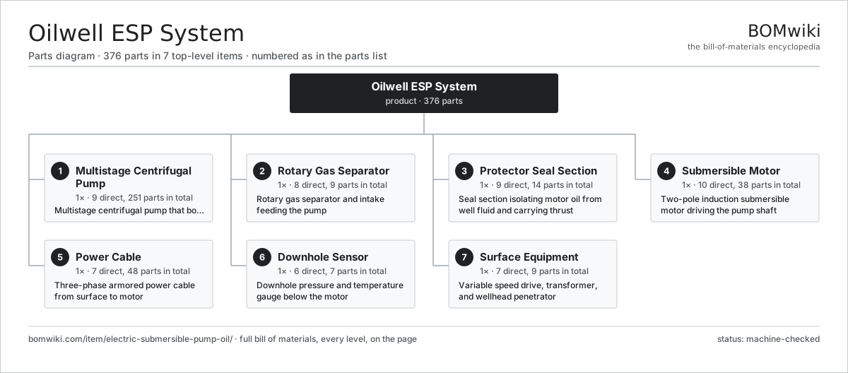
| # | Part | Qty | What it does |
|---|---|---|---|
| 1 | Multistage Centrifugal Pump 9 parts | 1× | Multistage centrifugal pump that boosts fluid pressure to surface |
| 2 | Rotary Gas Separator 8 parts | 1× | Rotary gas separator and intake feeding the pump |
| 3 | Protector Seal Section 9 parts | 1× | Seal section isolating motor oil from well fluid and carrying thrust |
| 4 | Submersible Motor 10 parts | 1× | Two-pole induction submersible motor driving the pump shaft |
| 5 | Power Cable 7 parts | 1× | Three-phase armored power cable from surface to motor |
| 6 | Downhole Sensor 6 parts | 1× | Downhole pressure and temperature gauge below the motor |
| 7 | Surface Equipment 7 parts | 1× | Variable speed drive, transformer, and wellhead penetrator |
3D model
No 3D model yet. Have a CAD file of this? Add a 3D model. STL renders right on this page; STEP, FreeCAD, and OpenSCAD sources are welcome too (openly licensed, like all 3D models on BOMwiki).
Build & assembly graph
expand / collapse · shared sub-assemblies converge · links to related products · est. labourTap an assembly to expand/collapse · tap a part to open it · use “Open page” for any node · drag to pan, scroll to zoom.
Bill of materials for Oilwell ESP System
7 top-level lines · 72 rows shown · 376 parts total · indented to 3 levels| # | Item / sub-assembly | Part no. | Qty/assy | Ext. qty | Parts | Type |
|---|---|---|---|---|---|---|
| 1 | Multistage Centrifugal Pump 9 parts | esp-pump | 1× | 1 | 251 | assembly |
| 1.1 | Pump Stage 2 parts | esp-pump-stage | 80× | 80 | 2 | assembly |
| 1.1.1 | Pump Impeller | esp-impeller | 1× | 80 | · | part |
| 1.1.2 | Pump Diffuser | esp-diffuser | 1× | 80 | · | part |
| 1.2 | Pump Housing | esp-pump-housing | 1× | 1 | · | part |
| 1.3 | Pump Shaft | esp-pump-shaft | 1× | 1 | · | part |
| 1.4 | Pump Discharge Head | esp-pump-head | 1× | 1 | · | part |
| 1.5 | Pump Intake Base | esp-pump-base | 1× | 1 | · | part |
| 1.6 | Stage Thrust Washer | esp-pump-thrust-washer | 80× | 80 | · | part |
| 1.7 | Ball Bearing | ball-bearing | 4× | 4 | · | part |
| 1.8 | O-Ring Set | oring-set | 2× | 2 | · | part |
| 1.9 | Fastener Set | fastener-set | 1× | 1 | · | part |
| 2 | Rotary Gas Separator 8 parts | esp-gas-separator | 1× | 1 | 9 | assembly |
| 2.1 | Separator Housing | esp-separator-housing | 1× | 1 | · | part |
| 2.2 | Separator Inducer | esp-separator-inducer | 1× | 1 | · | part |
| 2.3 | Separator Rotor | esp-separator-rotor | 1× | 1 | · | part |
| 2.4 | Separator Crossover | esp-separator-crossover | 1× | 1 | · | part |
| 2.5 | Intake Screen | esp-intake-screen | 1× | 1 | · | part |
| 2.6 | Pump Shaft | esp-pump-shaft | 1× | 1 | · | part |
| 2.7 | Ball Bearing | ball-bearing | 2× | 2 | · | part |
| 2.8 | O-Ring Set | oring-set | 1× | 1 | · | part |
| 3 | Protector Seal Section 9 parts | esp-protector | 1× | 1 | 14 | assembly |
| 3.1 | Protector Housing | esp-protector-housing | 1× | 1 | · | part |
| 3.2 | Labyrinth Chamber | esp-labyrinth-chamber | 2× | 2 | · | part |
| 3.3 | Elastomer Bag Chamber | esp-bag-chamber | 1× | 1 | · | part |
| 3.4 | Protector Thrust Bearing | esp-thrust-bearing | 1× | 1 | · | part |
| 3.5 | Protector Shaft | esp-protector-shaft | 1× | 1 | · | part |
| 3.6 | Shaft Mechanical Seal | esp-mechanical-seal | 2× | 2 | · | part |
| 3.7 | Oil Seal | oil-seal | 2× | 2 | · | part |
| 3.8 | Ball Bearing | ball-bearing | 2× | 2 | · | part |
| 3.9 | O-Ring Set | oring-set | 2× | 2 | · | part |
| 4 | Submersible Motor 10 parts | esp-motor | 1× | 1 | 38 | assembly |
| 4.1 | Stator Assembly 3 parts | stator-assembly | 1× | 1 | 3 | assembly |
| 4.1.1 | Stator Core (laminations) | stator-core | 1× | 1 | · | part |
| 4.1.2 | Copper Winding | copper-winding | 1× | 1 | · | part |
| 4.1.3 | Slot Insulation | stator-insulation | 1× | 1 | · | part |
| 4.2 | Rotor Assembly 4 parts | rotor-assembly | 1× | 1 | 19 | assembly |
| 4.2.1 | Rotor Shaft | rotor-shaft | 1× | 1 | · | part |
| 4.2.2 | Rotor Core | rotor-core | 1× | 1 | · | part |
| 4.2.3 | Neodymium Magnet | neodymium-magnet | 16× | 16 | · | part |
| 4.2.4 | Ball Bearing | ball-bearing | 1× | 1 | · | part |
| 4.3 | Motor Housing | esp-motor-housing | 1× | 1 | · | part |
| 4.4 | Motor Shaft | esp-motor-shaft | 1× | 1 | · | part |
| 4.5 | Motor Dielectric Oil | esp-motor-oil | 1× | 1 | · | part |
| 4.6 | Motor Thrust Bearing | esp-motor-thrust-bearing | 1× | 1 | · | part |
| 4.7 | Rotor Sleeve Bearing | esp-motor-rotor-bearing | 8× | 8 | · | part |
| 4.8 | Pothead Connector | esp-pothead | 1× | 1 | · | part |
| 4.9 | O-Ring Set | oring-set | 2× | 2 | · | part |
| 4.10 | Fastener Set | fastener-set | 1× | 1 | · | part |
| 5 | Power Cable 7 parts | esp-power-cable | 1× | 1 | 48 | assembly |
| 5.1 | Round Power Cable | esp-cable-round | 1× | 1 | · | part |
| 5.2 | Flat Power Cable | esp-cable-flat | 1× | 1 | · | part |
| 5.3 | Motor Lead Extension | esp-motor-lead-extension | 1× | 1 | · | part |
| 5.4 | Wire Bundle | wire-bundle | 3× | 3 | · | part |
| 5.5 | Cable Insulation | esp-cable-insulation | 1× | 1 | · | part |
| 5.6 | Cable Armor | esp-cable-armor | 1× | 1 | · | part |
| 5.7 | Cable Band | esp-cable-band | 40× | 40 | · | part |
| 6 | Downhole Sensor 6 parts | esp-sensor | 1× | 1 | 7 | assembly |
| 6.1 | Sensor Housing | esp-sensor-housing | 1× | 1 | · | part |
| 6.2 | Pressure Sensor | pressure-sensor | 2× | 2 | · | part |
| 6.3 | Temperature Probe | esp-temperature-probe | 1× | 1 | · | part |
| 6.4 | Vibration Sensor | esp-vibration-sensor | 1× | 1 | · | part |
| 6.5 | Connector | connector | 1× | 1 | · | part |
| 6.6 | O-Ring Set | oring-set | 1× | 1 | · | part |
| 7 | Surface Equipment 7 parts | esp-surface-equipment | 1× | 1 | 9 | assembly |
| 7.1 | Variable Speed Drive | esp-variable-speed-drive | 1× | 1 | · | part |
| 7.2 | Step-Up Transformer | esp-step-up-transformer | 1× | 1 | · | part |
| 7.3 | Wellhead Penetrator | esp-wellhead-penetrator | 1× | 1 | · | part |
| 7.4 | Junction Box | esp-junction-box | 1× | 1 | · | part |
| 7.5 | Power Supply | power-supply | 1× | 1 | · | part |
| 7.6 | Microcontroller | mcu | 1× | 1 | · | part |
| 7.7 | Connector | connector | 3× | 3 | · | part |
Related products
same domain, ranked by shared parts Drilling Mud Degasser
154 parts · shares 11 with this page
Drilling Mud Degasser
154 parts · shares 11 with this page
 Drilling Mud Mixing System
135 parts · shares 11 with this page
Drilling Mud Mixing System
135 parts · shares 11 with this page
 Oilwell Cementing Unit
902 parts · shares 11 with this page
Oilwell Cementing Unit
902 parts · shares 11 with this page
 Shale Shaker
201 parts · shares 11 with this page
Shale Shaker
201 parts · shares 11 with this page
 Sulfur Recovery Unit
206 parts · shares 11 with this page
Sulfur Recovery Unit
206 parts · shares 11 with this page
Sourcing: possible vendors
Browse the supplier directory → Prices, MOQ, and lead times are algorithmic estimates, not quotes, and not claims about these companies. Company mappings are curated by keyword; est. price band $10k–$50M. How estimates work| Vendor | HQ | Specialty | MOQ | Lead time |
|---|---|---|---|---|
|
🇺🇸SLB
slb.com ↗
|
Houston, US | Oilfield services & equipment | made to order | 24–48 wks |
| halliburton.com ↗ | Houston, US | Oilfield services | made to order | 24–48 wks |
| bakerhughes.com ↗ | Houston, US | Energy technology | made to order | 24–48 wks |
|
🇺🇸NOV
nov.com ↗
|
Houston, US | Drilling equipment | made to order | 24–48 wks |
| technipfmc.com ↗ | London, GB | Subsea & surface systems | made to order | 24–48 wks |
1,203-word article