Well Test Separator Skid
ProductOverview
A well test separator skid is a compact, often portable separator used to measure how much oil, gas and water a single well produces. Operators need this number for each well to manage the reservoir, allocate production among partners, detect problems such as water breakthrough or declining gas, and report to regulators. Rather than build a permanent separator at every well, a facility routes one well at a time to a shared test separator through a test manifold, measures its rates over a test period, and then switches to the next well.
The skid is a self-contained three-phase separator with flow meters on each outlet and a flow computer that totalizes the results. Unlike a Three-Phase Production Separator sized for bulk production, the Test Separator Vessel is sized for accurate measurement and a defined test duration, so it is smaller and built for easy transport and hookup. Many units are mounted on a road-transportable skid with lifting and tie-down points so the same separator can serve several well pads.
How a well test works
The well under test is lined up to the skid through the Inlet Manifold manifold, which isolates that well and routes its flow into the separator while the other wells continue to the production separator. An inlet diverter breaks the momentum of the wellstream, and the fluid separates inside the vessel into gas at the top, oil over the weir, and water at the bottom, the same way a production separator works. The difference is that each outlet now carries a meter.
A test runs for a set period, often several hours to a full day, long enough for the well to stabilize at the test conditions and for the readings to average out short-term slugging. The Control and Test Computer flow computer records gas, oil and water continuously and reports the average daily rates and the cumulative volumes for the test. Sampling points on the inlet and water lines let the operator check fluid properties and confirm the water-cut reading.
Measuring the three phases
Gas is measured by the Gas Metering Section section, usually an orifice plate sized and calculated per AGA 3, with a differential pressure transmitter across the plate and a temperature transmitter for density correction. A back-pressure valve on the gas outlet holds the vessel at the test pressure, which fixes the gas density used in the calculation.
Oil leaves through the Oil Metering Section section, where a turbine or coriolis meter measures the liquid rate. Because the oil may still carry a little water, an inline water-cut meter corrects the reading to a true oil rate. Water leaves through the Water Metering Section section with its own turbine or magnetic flow meter. The flow computer combines all three measurements into the well's gas-oil ratio, water cut and total liquid rate.
Level control and the flow computer
Steady levels are essential for accurate liquid metering, because a swinging level dumps liquid in surges that the meters struggle to follow. The control section uses an interface transmitter and an oil level transmitter to drive the two dump valves, holding both the oil-water interface and the oil level steady so the dumps are smooth. The Control and Test Computer flow computer ties the meters together, applies the AGA and meter-factor corrections, and presents the totals on an operator display. Reflex sight glasses and level switches back up the automatic control and feed the shutdown system.
Relief and shutdown
Even though it is a small vessel, the test separator holds full well pressure and needs the same protection as any production vessel. The Relief and Shutdown section provides an ASME relief valve and a backup rupture disc for overpressure, and an inlet emergency shutdown valve closes on a trip from high or low level, high or low pressure, or fire and gas detection. Pressure transmitters report vessel conditions to the safety system, and the shutdown brings the skid to a safe state without operator action.
Transport and use
The Transportable Skid is built as a single liftable and trailerable unit with the vessel, meters, valves, controls and wiring already plumbed and terminated in a junction box, so field hookup is just the well connection, the outlet lines and power. This makes the skid easy to move between pads and quick to bring into service. Well test separators are used across onshore and offshore production, on new wells during initial flow testing, and on producing fields for routine periodic well tests. By giving an accurate per-well measurement, the skid supports reservoir management and production allocation without dedicating a full separator to each well.
Well Test Separator Skid parts and their functions
8 top-level parts · 56 parts in total · full bill of materials below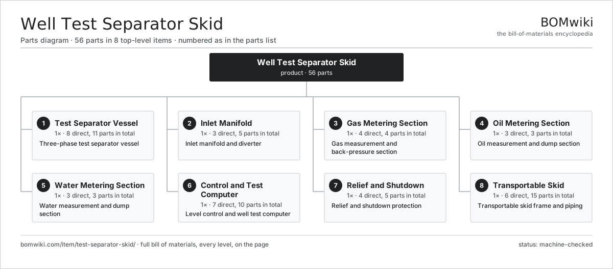
| # | Part | Qty | What it does |
|---|---|---|---|
| 1 | Test Separator Vessel 8 parts | 1× | Three-phase test separator vessel |
| 2 | Inlet Manifold 3 parts | 1× | Inlet manifold and diverter |
| 3 | Gas Metering Section 4 parts | 1× | Gas measurement and back-pressure section |
| 4 | Oil Metering Section 3 parts | 1× | Oil measurement and dump section |
| 5 | Water Metering Section 3 parts | 1× | Water measurement and dump section |
| 6 | Control and Test Computer 7 parts | 1× | Level control and well test computer |
| 7 | Relief and Shutdown 4 parts | 1× | Relief and shutdown protection |
| 8 | Transportable Skid 6 parts | 1× | Transportable skid frame and piping |
3D model
No 3D model yet. Have a CAD file of this? Add a 3D model. STL renders right on this page; STEP, FreeCAD, and OpenSCAD sources are welcome too (openly licensed, like all 3D models on BOMwiki).
Build & assembly graph
expand / collapse · shared sub-assemblies converge · links to related products · est. labourTap an assembly to expand/collapse · tap a part to open it · use “Open page” for any node · drag to pan, scroll to zoom.
Bill of materials for Well Test Separator Skid
8 top-level lines · 46 rows shown · 56 parts total · indented to 3 levels| # | Item / sub-assembly | Part no. | Qty/assy | Ext. qty | Parts | Type |
|---|---|---|---|---|---|---|
| 1 | Test Separator Vessel 8 parts | test-separator-skid-vessel | 1× | 1 | 11 | assembly |
| 1.1 | Shell Course Ring | test-separator-skid-shell | 2× | 2 | · | part |
| 1.2 | Vessel Head | test-separator-skid-head | 2× | 2 | · | part |
| 1.3 | Nozzle Set | test-separator-skid-nozzle-set | 1× | 1 | · | part |
| 1.4 | Saddle Support | test-separator-skid-saddle | 2× | 2 | · | part |
| 1.5 | Weir Plate | test-separator-skid-weir | 1× | 1 | · | part |
| 1.6 | Mist Extractor Pad | test-separator-skid-mist-pad | 1× | 1 | · | part |
| 1.7 | Manway | test-separator-skid-manway | 1× | 1 | · | part |
| 1.8 | Fastener Set | fastener-set | 1× | 1 | · | part |
| 2 | Inlet Manifold 3 parts | test-separator-skid-inlet | 1× | 1 | 5 | assembly |
| 2.1 | Inlet Diverter | test-separator-skid-inlet-diverter | 1× | 1 | · | part |
| 2.2 | Manifold Valve | test-separator-skid-manifold-valve | 3× | 3 | · | part |
| 2.3 | Inlet Sample Point | test-separator-skid-sample-point | 1× | 1 | · | part |
| 3 | Gas Metering Section 4 parts | test-separator-skid-gas-metering | 1× | 1 | 4 | assembly |
| 3.1 | Orifice Gas Meter | test-separator-skid-orifice-meter | 1× | 1 | · | part |
| 3.2 | Gas Back-Pressure Valve | test-separator-skid-gas-bpv | 1× | 1 | · | part |
| 3.3 | Gas DP Transmitter | test-separator-skid-gas-transmitter | 1× | 1 | · | part |
| 3.4 | Gas Temperature Transmitter | test-separator-skid-gas-temp | 1× | 1 | · | part |
| 4 | Oil Metering Section 3 parts | test-separator-skid-oil-metering | 1× | 1 | 3 | assembly |
| 4.1 | Oil Flow Meter | test-separator-skid-oil-meter | 1× | 1 | · | part |
| 4.2 | Oil Dump Valve | test-separator-skid-oil-dump-valve | 1× | 1 | · | part |
| 4.3 | Water-Cut Meter | test-separator-skid-watercut-meter | 1× | 1 | · | part |
| 5 | Water Metering Section 3 parts | test-separator-skid-water-metering | 1× | 1 | 3 | assembly |
| 5.1 | Water Flow Meter | test-separator-skid-water-meter | 1× | 1 | · | part |
| 5.2 | Water Dump Valve | test-separator-skid-water-dump-valve | 1× | 1 | · | part |
| 5.3 | Water Sample Point | test-separator-skid-water-sample | 1× | 1 | · | part |
| 6 | Control and Test Computer 7 parts | test-separator-skid-control | 1× | 1 | 10 | assembly |
| 6.1 | Interface Transmitter | test-separator-skid-interface-transmitter | 1× | 1 | · | part |
| 6.2 | Oil Level Transmitter | test-separator-skid-oil-transmitter | 1× | 1 | · | part |
| 6.3 | Level Controller | test-separator-skid-controller | 2× | 2 | · | part |
| 6.4 | Well Test Flow Computer | test-separator-skid-flow-computer | 1× | 1 | · | part |
| 6.5 | LCD Panel | lcd-panel | 1× | 1 | · | part |
| 6.6 | Sight Glass | test-separator-skid-sight-glass | 2× | 2 | · | part |
| 6.7 | Level Switch | test-separator-skid-level-switch | 2× | 2 | · | part |
| 7 | Relief and Shutdown 4 parts | test-separator-skid-relief | 1× | 1 | 5 | assembly |
| 7.1 | Relief Valve | test-separator-skid-relief-valve | 1× | 1 | · | part |
| 7.2 | Rupture Disc | test-separator-skid-rupture-disc | 1× | 1 | · | part |
| 7.3 | Shutdown Valve | test-separator-skid-sdv | 1× | 1 | · | part |
| 7.4 | Pressure Sensor | pressure-sensor | 2× | 2 | · | part |
| 8 | Transportable Skid 6 parts | test-separator-skid-frame | 1× | 1 | 15 | assembly |
| 8.1 | Skid Base | test-separator-skid-base | 1× | 1 | · | part |
| 8.2 | Pipe Spool | test-separator-skid-pipe-spool | 5× | 5 | · | part |
| 8.3 | Pipe Support | test-separator-skid-pipe-support | 6× | 6 | · | part |
| 8.4 | Walkway and Ladder | test-separator-skid-walkway | 1× | 1 | · | part |
| 8.5 | Junction Box | test-separator-skid-junction-box | 1× | 1 | · | part |
| 8.6 | Wire Bundle | wire-bundle | 1× | 1 | · | part |
Related products
same domain, ranked by shared parts Coiled Tubing Unit
190 parts · shares 1 with this page
Coiled Tubing Unit
190 parts · shares 1 with this page
 Drilling Mud Degasser
154 parts · shares 1 with this page
Drilling Mud Degasser
154 parts · shares 1 with this page
 Drilling Mud Mixing System
135 parts · shares 1 with this page
Drilling Mud Mixing System
135 parts · shares 1 with this page
 Drilling Top Drive
181 parts · shares 1 with this page
Drilling Top Drive
181 parts · shares 1 with this page
 Gas Engine Driven Compressor
217 parts · shares 1 with this page
Gas Engine Driven Compressor
217 parts · shares 1 with this page
Sourcing: possible vendors
Browse the supplier directory → Prices, MOQ, and lead times are algorithmic estimates, not quotes, and not claims about these companies. Company mappings are curated by keyword; est. price band $10k–$50M. How estimates work| Vendor | HQ | Specialty | MOQ | Lead time |
|---|---|---|---|---|
|
🇺🇸SLB
slb.com ↗
|
Houston, US | Oilfield services & equipment | made to order | 24–48 wks |
| halliburton.com ↗ | Houston, US | Oilfield services | made to order | 24–48 wks |
| bakerhughes.com ↗ | Houston, US | Energy technology | made to order | 24–48 wks |
|
🇺🇸NOV
nov.com ↗
|
Houston, US | Drilling equipment | made to order | 24–48 wks |
| technipfmc.com ↗ | London, GB | Subsea & surface systems | made to order | 24–48 wks |
793-word article