Natural Gas City Gate Station
ProductOverview
A natural gas city gate station is the boundary between a high-pressure transmission pipeline and a lower-pressure municipal distribution network. At this point the gas utility takes legal and physical custody of the gas, measures exactly how much arrives, conditions it for distribution and adds the smell that lets customers detect a leak. The station sits on a fenced pad and is usually built on one or more steel skids fabricated and tested in a shop before installation. Inlet pressure from the transmission line typically runs 20 to 70 bar, while the distribution grid downstream operates between about 1 and 7 bar, so the central job of the station is a controlled, safe and accurately metered pressure cut.
Gas enters through the Inlet Metering and Isolation section, passes through Inlet Filter Separator and Gas Preheater, is reduced in pressure across the Pressure Regulation Run assemblies, is protected by the Overpressure Protection System, receives odorant from the Odorant Injection Package, and leaves through the Station Piping and Manifold to the local mains. The whole sequence is monitored by the Control and Telemetry package, which reports flow, pressure and alarms back to the utility control center.
Custody metering
Because money changes hands at the city gate, measurement is held to custody transfer accuracy. The inlet line carries a multipath ultrasonic meter installed in a honed straight-run spool with an upstream flow conditioner, an arrangement set by ISO 5167 and AGA Report 9 to give a developed, swirl-free velocity profile. The meter feeds a flow computer that corrects raw volume for pressure and flowing temperature and converts it to energy. An online gas chromatograph reports composition and calorific value so the energy figure reflects the actual gas, not an assumed mixture. Static and differential pressure transmitters and an RTD temperature transmitter supply the live process variables. Typical accuracy is around ±0.5% of reading, with the meter chosen for a turndown wide enough to cover both winter peak and summer base loads.
Pressure regulation
Pressure reduction is done in regulator runs, and the station carries two runs so one can be taken out of service without interrupting supply. Each run uses a worker regulator in series with a monitor regulator. The worker controls outlet pressure to setpoint under normal conditions. The monitor is set slightly higher and stays wide open until the worker fails, at which point it assumes control and holds a safe outlet pressure. Pilot-operated designs are common because they hold a tight setpoint across a wide flow range. Dropping from tens of bar to a few bar through a single restriction produces high gas velocity and noise, so the runs use low-noise trim with staged pressure letdown. A downstream sensing line feeds the pilots, and inlet and outlet pressure transmitters report each run to the controller.
Odorization
Pipeline gas is almost odorless, so the station injects an odorant to give it the recognizable smell that warns of a leak. This station odorizes the gas as it passes. Odorant, usually a tert-butyl mercaptan and tetrahydrothiophene blend or ethyl mercaptan, is held in a sealed Odorant Storage Tank under a nitrogen blanket. A metering Odorant Injection Pump delivers odorant through an atomizing nozzle into the gas stream, and the Odorizer Controller paces injection to the metered flow so concentration stays near 8 to 16 mg/m3 regardless of load. Check valves prevent backflow, a strainer protects the pump, and a carbon vapor scrubber treats tank vents. Refilling uses a closed dry-break coupling to avoid spills and exposure.
Gas preheating
When gas expands across the regulators its temperature falls through the Joule-Thomson effect, roughly several degrees per ten bar of pressure drop. Without heating, the metal and any entrained moisture can chill below the frost or hydrate point, which fouls valves and can form ice. The Gas Preheater is an indirect waterbath heater: a burner fires a fire tube immersed in a bath of water or glycol, and the process gas passes through a separate coil in the same bath. Heating the gas before the cut keeps the downstream temperature above the threshold. Duty is sized to the design flow and pressure drop, commonly 150 to 600 kW, with a flame safeguard controller managing burner ignition and shutdown.
Overpressure protection
Distribution mains and customer equipment are rated for far lower pressure than the inlet, so overpressure protection is independent of the regulators that could fail. The Overpressure Protection System combines a slam-shut valve and a relief valve. The slam-shut is a spring-loaded shutoff that trips closed within a fraction of a second if outlet pressure rises above its set point, isolating the run. A pilot-operated relief valve provides a second layer by venting excess gas through a flame-arrested stack to atmosphere. This staged protection follows EN 12186 and ASME B31.8 practice for gas pressure regulating installations.
Control and telemetry
The Control and Telemetry package gathers every instrument signal into a remote terminal unit and reports flow totals, pressures, temperatures, odorant level and alarms to the utility SCADA host over a radio or cellular link. Pressure transmitters such as Pressure Sensor units feed the controller, which can also annunciate filter fouling, slam-shut trips and odorant low level. Many city gates sit away from grid power, so the package is solar charged with a backup battery, and all electronics are housed in a hazardous-area rated cabinet wired to field devices through intrinsically safe barriers.
Natural Gas City Gate Station parts and their functions
8 top-level parts · 112 parts in total · full bill of materials below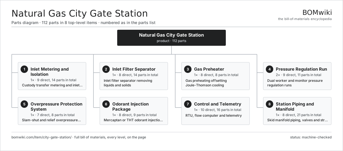
| # | Part | Qty | What it does |
|---|---|---|---|
| 1 | Inlet Metering and Isolation 9 parts | 1× | Custody transfer metering and inlet isolation |
| 2 | Inlet Filter Separator 8 parts | 1× | Inlet filter separator removing liquids and solids |
| 3 | Gas Preheater 8 parts | 1× | Gas preheating offsetting Joule-Thomson cooling |
| 4 | Pressure Regulation Run 9 parts | 2× | Dual worker and monitor pressure regulation runs |
| 5 | Overpressure Protection System 7 parts | 1× | Slam-shut and relief overpressure protection |
| 6 | Odorant Injection Package 8 parts | 1× | Mercaptan or THT odorant injection package |
| 7 | Control and Telemetry 10 parts | 1× | RTU, flow computer and telemetry |
| 8 | Station Piping and Manifold 8 parts | 1× | Skid manifold piping, valves and structure |
3D model
No 3D model yet. Have a CAD file of this? Add a 3D model. STL renders right on this page; STEP, FreeCAD, and OpenSCAD sources are welcome too (openly licensed, like all 3D models on BOMwiki).
Build & assembly graph
expand / collapse · shared sub-assemblies converge · links to related products · est. labourTap an assembly to expand/collapse · tap a part to open it · use “Open page” for any node · drag to pan, scroll to zoom.
Bill of materials for Natural Gas City Gate Station
8 top-level lines · 75 rows shown · 112 parts total · indented to 3 levels| # | Item / sub-assembly | Part no. | Qty/assy | Ext. qty | Parts | Type |
|---|---|---|---|---|---|---|
| 1 | Inlet Metering and Isolation 9 parts | city-gate-station-inlet-metering | 1× | 1 | 14 | assembly |
| 1.1 | Inlet Isolation Valve | city-gate-station-inlet-valve | 1× | 1 | · | part |
| 1.2 | Ultrasonic Custody Meter | city-gate-station-ultrasonic-meter | 1× | 1 | · | part |
| 1.3 | Meter Run Spool | city-gate-station-meter-tube | 2× | 2 | · | part |
| 1.4 | Flow Conditioner | city-gate-station-flow-conditioner | 1× | 1 | · | part |
| 1.5 | Flow Computer | city-gate-station-flow-computer | 1× | 1 | · | part |
| 1.6 | Gas Chromatograph | city-gate-station-gas-chromatograph | 1× | 1 | · | part |
| 1.7 | Pressure Sensor | pressure-sensor | 2× | 2 | · | part |
| 1.8 | Temperature Transmitter | city-gate-station-temp-transmitter | 1× | 1 | · | part |
| 1.9 | Fastener Set | fastener-set | 4× | 4 | · | part |
| 2 | Inlet Filter Separator 8 parts | city-gate-station-filtration | 1× | 1 | 14 | assembly |
| 2.1 | Filter Separator Vessel | city-gate-station-separator-vessel | 1× | 1 | · | part |
| 2.2 | Coalescing Filter Element | city-gate-station-filter-element | 6× | 6 | · | part |
| 2.3 | Mist Eliminator Pad | city-gate-station-demister-pad | 1× | 1 | · | part |
| 2.4 | Liquid Drain Pot | city-gate-station-drain-pot | 1× | 1 | · | part |
| 2.5 | Automatic Drain Valve | city-gate-station-drain-valve | 1× | 1 | · | part |
| 2.6 | Differential Pressure Gauge | city-gate-station-diff-gauge | 1× | 1 | · | part |
| 2.7 | O-Ring Set | oring-set | 1× | 1 | · | part |
| 2.8 | Fastener Set | fastener-set | 2× | 2 | · | part |
| 3 | Gas Preheater 8 parts | city-gate-station-preheater | 1× | 1 | 8 | assembly |
| 3.1 | Waterbath Shell | city-gate-station-waterbath-shell | 1× | 1 | · | part |
| 3.2 | Fire Tube | city-gate-station-fire-tube | 1× | 1 | · | part |
| 3.3 | Process Gas Coil | city-gate-station-gas-coil | 1× | 1 | · | part |
| 3.4 | Heater Burner | city-gate-station-burner | 1× | 1 | · | part |
| 3.5 | Flame Safeguard Controller | city-gate-station-burner-control | 1× | 1 | · | part |
| 3.6 | Bath Thermostat | city-gate-station-bath-thermostat | 1× | 1 | · | part |
| 3.7 | Exhaust Stack | city-gate-station-stack | 1× | 1 | · | part |
| 3.8 | Expansion Tank | city-gate-station-expansion-tank | 1× | 1 | · | part |
| 4 | Pressure Regulation Run 9 parts | city-gate-station-regulator-run | 2× | 2 | 11 | assembly |
| 4.1 | Worker Regulator | city-gate-station-worker-regulator | 1× | 2 | · | part |
| 4.2 | Monitor Regulator | city-gate-station-monitor-regulator | 1× | 2 | · | part |
| 4.3 | Regulator Pilot | city-gate-station-pilot | 2× | 4 | · | part |
| 4.4 | Run Inlet Valve | city-gate-station-run-inlet-valve | 1× | 2 | · | part |
| 4.5 | Run Outlet Valve | city-gate-station-run-outlet-valve | 1× | 2 | · | part |
| 4.6 | Low-Noise Trim | city-gate-station-noise-trim | 1× | 2 | · | part |
| 4.7 | Pressure Sensor | pressure-sensor | 2× | 4 | · | part |
| 4.8 | Sensing Control Line | city-gate-station-control-line | 1× | 2 | · | part |
| 4.9 | O-Ring Set | oring-set | 1× | 2 | · | part |
| 5 | Overpressure Protection System 7 parts | city-gate-station-relief-system | 1× | 1 | 8 | assembly |
| 5.1 | Slam-Shut Valve | city-gate-station-slam-shut | 1× | 1 | · | part |
| 5.2 | Pressure Relief Valve | city-gate-station-relief-valve | 1× | 1 | · | part |
| 5.3 | Relief Valve Pilot | city-gate-station-relief-pilot | 1× | 1 | · | part |
| 5.4 | Vent Stack | city-gate-station-vent-stack | 1× | 1 | · | part |
| 5.5 | Coil Spring | coil-spring | 2× | 2 | · | part |
| 5.6 | Pressure Sensor | pressure-sensor | 1× | 1 | · | part |
| 5.7 | O-Ring Set | oring-set | 1× | 1 | · | part |
| 6 | Odorant Injection Package 8 parts | city-gate-station-odorizer | 1× | 1 | 9 | assembly |
| 6.1 | Odorant Storage Tank | city-gate-station-odorant-tank | 1× | 1 | · | part |
| 6.2 | Odorant Injection Pump | city-gate-station-injection-pump | 1× | 1 | · | part |
| 6.3 | Injection Nozzle | city-gate-station-injection-nozzle | 1× | 1 | · | part |
| 6.4 | Odorant Line Strainer | city-gate-station-odorant-filter | 1× | 1 | · | part |
| 6.5 | Odorizer Controller | city-gate-station-odorizer-controller | 1× | 1 | · | part |
| 6.6 | Odorant Check Valve | city-gate-station-check-valve | 2× | 2 | · | part |
| 6.7 | Closed Fill Coupling | city-gate-station-fill-coupling | 1× | 1 | · | part |
| 6.8 | Vapor Scrubber | city-gate-station-vapor-scrubber | 1× | 1 | · | part |
| 7 | Control and Telemetry 10 parts | city-gate-station-control-scada | 1× | 1 | 16 | assembly |
| 7.1 | Remote Terminal Unit | city-gate-station-rtu | 1× | 1 | · | part |
| 7.2 | Telemetry Radio | city-gate-station-radio | 1× | 1 | · | part |
| 7.3 | Power Supply | power-supply | 1× | 1 | · | part |
| 7.4 | Solar Panel | city-gate-station-solar-panel | 1× | 1 | · | part |
| 7.5 | Backup Battery | city-gate-station-battery | 1× | 1 | · | part |
| 7.6 | Instrument Cabinet | city-gate-station-io-cabinet | 1× | 1 | · | part |
| 7.7 | Bare PCB | pcb-bare | 1× | 1 | · | part |
| 7.8 | Microcontroller | mcu | 1× | 1 | · | part |
| 7.9 | Wire Bundle | wire-bundle | 2× | 2 | · | part |
| 7.10 | Connector | connector | 6× | 6 | · | part |
| 8 | Station Piping and Manifold 8 parts | city-gate-station-station-piping | 1× | 1 | 21 | assembly |
| 8.1 | Inlet Header | city-gate-station-inlet-header | 1× | 1 | · | part |
| 8.2 | Outlet Header | city-gate-station-outlet-header | 1× | 1 | · | part |
| 8.3 | Emergency Bypass Valve | city-gate-station-bypass-valve | 1× | 1 | · | part |
| 8.4 | Blowdown Valve | city-gate-station-blowdown-valve | 2× | 2 | · | part |
| 8.5 | Insulating Joint | city-gate-station-insulating-joint | 1× | 1 | · | part |
| 8.6 | Pipe Support | city-gate-station-pipe-support | 8× | 8 | · | part |
| 8.7 | Skid Frame | city-gate-station-skid-frame | 1× | 1 | · | part |
| 8.8 | Fastener Set | fastener-set | 6× | 6 | · | part |
Related products
same domain, ranked by shared parts Amine Gas Sweetening Unit
3,543 parts · shares 2 with this page
Amine Gas Sweetening Unit
3,543 parts · shares 2 with this page
 Condensate Stabilizer Column
2,234 parts · shares 2 with this page
Condensate Stabilizer Column
2,234 parts · shares 2 with this page
 Gas Metering Skid
1,491 parts · shares 2 with this page
Gas Metering Skid
1,491 parts · shares 2 with this page
 Gas Pressure Regulating Station
133 parts · shares 2 with this page
Gas Pressure Regulating Station
133 parts · shares 2 with this page
 Inline Inspection Pig
248 parts · shares 2 with this page
JT Gas Dew Point Skid
441 parts · shares 2 with this page
Inline Inspection Pig
248 parts · shares 2 with this page
JT Gas Dew Point Skid
441 parts · shares 2 with this page
Sourcing: possible vendors
Browse the supplier directory → Prices, MOQ, and lead times are algorithmic estimates, not quotes, and not claims about these companies. Company mappings are curated by keyword; est. price band $10k–$50M. How estimates work| Vendor | HQ | Specialty | MOQ | Lead time |
|---|---|---|---|---|
|
🇺🇸SLB
slb.com ↗
|
Houston, US | Oilfield services & equipment | made to order | 24–48 wks |
| halliburton.com ↗ | Houston, US | Oilfield services | made to order | 24–48 wks |
| bakerhughes.com ↗ | Houston, US | Energy technology | made to order | 24–48 wks |
|
🇺🇸NOV
nov.com ↗
|
Houston, US | Drilling equipment | made to order | 24–48 wks |
| technipfmc.com ↗ | London, GB | Subsea & surface systems | made to order | 24–48 wks |
942-word article