Mud Desander and Desilter
ProductOverview
A mud desander and desilter is a solids-control unit that pulls fine drilled solids out of water-based or oil-based drilling fluid so the fluid can be reused. It sits in the rig solids-control train after the shale shaker, which catches the coarse cuttings, and before the decanting centrifuge, which polishes out the ultrafine barite-sized particles. Removing silt and sand keeps mud weight and viscosity in range, protects the mud pumps and downhole tools from abrasion, and cuts the cost of mixing new mud.
The unit is a combined machine, often called a mud cleaner. The Desander Bank uses two large 12 in cones to strip sand-sized particles, and the Desilter Bank uses sixteen small 4 in cones to strip silt. Both banks discharge their underflow onto one shared vibrating screen, the Underliner Shaker Screen Deck, which recovers the liquid mud and weighting material while throwing the dry solids off the end. Putting both cone sizes over a single screen on one Skid Frame saves deck space on the rig and recovers expensive barite that plain desilter cones would otherwise discard.
How a hydrocyclone works
A hydrocyclone has no moving parts. Mud enters tangentially through the Desander Inlet Head and spins down the cone wall, building a high centrifugal field. Heavy solids are thrown outward and spiral down to the narrow Desander Apex Nozzle at the bottom, leaving as underflow. The lighter cleaned mud reverses into an inner upward vortex and exits through the Desander Vortex Finder, the vortex finder, at the top. Cut point, the particle size at which half the solids report to underflow, is set by cone diameter: the 12 in desander cone cuts near 74 microns, while the 4 in desilter cone generates a much higher G force and cuts down to 15 to 25 microns. The desilter cones are fed through the Desilter Inlet Manifold so all sixteen run at the same inlet pressure.
Cones run by pressure, not gravity, so feed pressure controls performance. The unit holds a feed inlet pressure of 30 to 45 psi, with most cone designs optimized near 32 psi. Below the design pressure the cones lose separation; well above it they wear faster and can pull too much liquid into the underflow.
Feed pump and pressure control
The Centrifugal Feed Pump is a dedicated centrifugal pump that supplies the cone head. It must be sized for the unit alone, since sharing a pump between the cones and another consumer makes inlet pressure swing as mud weight changes. The wet end uses high-chrome white iron in the Pump Casing, Pump Impeller, and Pump Wear Plate because drilling mud is abrasive and would erode a standard cast-iron pump in days. The shaft runs on a Pump Mechanical Seal with silicon carbide faces. The pump and its motor share the Pump Baseplate, and the standard pump drive uses the same kind of Stator Assembly and Rotor Assembly found across the unit motors. Feed and manifold pressure are read through the Instrumentation Package package: a Feed Pressure Gauge at the pump discharge and a Manifold Pressure Gauge on each cone bank let the operator spot a plugged or worn cone by its pressure signature.
Underliner screen deck
Plain desander and desilter cones throw their underflow straight to the waste pit, which discards usable barite along with the silt. The combined mud cleaner instead drops the underflow through the Underflow Drain Pan onto the Underliner Shaker Screen Deck. This is a small linear-motion vibrating screen. Two Vibrator Motor units, mounted to run counter-rotating, cancel their side-to-side forces and leave a straight-line throw that conveys solids uphill across the Screen Panel mesh. Each vibrator motor carries an adjustable Eccentric Weight on its Rotor Assembly to set the G force, and runs on heavy-duty Ball Bearing sets sized for vibratory load. The screen basket is decoupled from the static skid by eight Screen Isolation Spring coil springs so the vibration stays in the basket and does not crack the frame. The mesh is selected per API RP 13C to match the desilter cut point, finer mesh recovers more barite but cuts throughput.
Materials and wear
Every surface that sees flowing mud is built to resist abrasion. The cone bodies, inlet heads, vortex finders, and apex nozzles are cast polyurethane or polyurethane-lined steel, and the apex on the desander is often ceramic-lined because the tip wears fastest. The Feed Manifold and distributor spools are polyurethane-lined carbon steel. Apex wear is the most common service item: as the nozzle erodes, the underflow opening grows, the discharge turns from a fine spray to a rope, and the cone starts dumping liquid mud. Operators watch the underflow pattern and swap apex nozzles on a schedule. The Cone Clamp band clamps let a worn cone be pulled and replaced without tools.
Variants and use
Units are configured by hole size and flow rate. A small workover rig might run a desilter-only unit, while a deep well on heavy mud runs the full combined desander and desilter with a finer underliner screen. On unweighted water-based mud the screen is sometimes omitted and the underflow sent straight to waste, since there is no barite to recover. The whole package ships as one skid with Lifting Lug pad-eyes for crane handling and a Mud Pit Compartment compartment beneath, so it can be moved between rigs and tied into the existing pit system with flanged connections.
Mud Desander and Desilter parts and their functions
9 top-level parts · 236 parts in total · full bill of materials below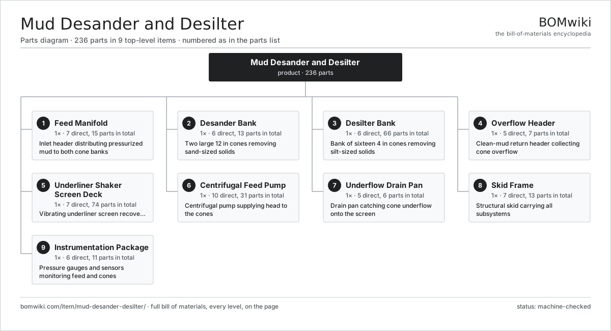
| # | Part | Qty | What it does |
|---|---|---|---|
| 1 | Feed Manifold 7 parts | 1× | Inlet header distributing pressurized mud to both cone banks |
| 2 | Desander Bank 6 parts | 1× | Two large 12 in cones removing sand-sized solids |
| 3 | Desilter Bank 6 parts | 1× | Bank of sixteen 4 in cones removing silt-sized solids |
| 4 | Overflow Header 5 parts | 1× | Clean-mud return header collecting cone overflow |
| 5 | Underliner Shaker Screen Deck 7 parts | 1× | Vibrating underliner screen recovering mud from underflow |
| 6 | Centrifugal Feed Pump 10 parts | 1× | Centrifugal pump supplying head to the cones |
| 7 | Underflow Drain Pan 5 parts | 1× | Drain pan catching cone underflow onto the screen |
| 8 | Skid Frame 7 parts | 1× | Structural skid carrying all subsystems |
| 9 | Instrumentation Package 6 parts | 1× | Pressure gauges and sensors monitoring feed and cones |
3D model
No 3D model yet. Have a CAD file of this? Add a 3D model. STL renders right on this page; STEP, FreeCAD, and OpenSCAD sources are welcome too (openly licensed, like all 3D models on BOMwiki).
Build & assembly graph
expand / collapse · shared sub-assemblies converge · links to related products · est. labourTap an assembly to expand/collapse · tap a part to open it · use “Open page” for any node · drag to pan, scroll to zoom.
Bill of materials for Mud Desander and Desilter
9 top-level lines · 81 rows shown · 236 parts total · indented to 3 levels| # | Item / sub-assembly | Part no. | Qty/assy | Ext. qty | Parts | Type |
|---|---|---|---|---|---|---|
| 1 | Feed Manifold 7 parts | mud-desander-desilter-feed-manifold | 1× | 1 | 15 | assembly |
| 1.1 | Feed Header Pipe | mud-desander-desilter-feed-header-pipe | 1× | 1 | · | part |
| 1.2 | Feed Flange | mud-desander-desilter-feed-flange | 4× | 4 | · | part |
| 1.3 | Bank Isolation Valve | mud-desander-desilter-isolation-valve | 2× | 2 | · | part |
| 1.4 | Feed Distributor Spool | mud-desander-desilter-feed-distributor | 2× | 2 | · | part |
| 1.5 | Flange Gasket | mud-desander-desilter-feed-gasket | 4× | 4 | · | part |
| 1.6 | O-Ring Set | oring-set | 1× | 1 | · | part |
| 1.7 | Fastener Set | fastener-set | 1× | 1 | · | part |
| 2 | Desander Bank 6 parts | mud-desander-desilter-desander-bank | 1× | 1 | 13 | assembly |
| 2.1 | Desander Cone (12 in) | mud-desander-desilter-desander-cone | 2× | 2 | · | part |
| 2.2 | Desander Inlet Head | mud-desander-desilter-desander-inlet-head | 2× | 2 | · | part |
| 2.3 | Desander Vortex Finder | mud-desander-desilter-desander-overflow-pipe | 2× | 2 | · | part |
| 2.4 | Desander Apex Nozzle | mud-desander-desilter-desander-apex | 2× | 2 | · | part |
| 2.5 | Cone Clamp | mud-desander-desilter-cone-clamp | 4× | 4 | · | part |
| 2.6 | Fastener Set | fastener-set | 1× | 1 | · | part |
| 3 | Desilter Bank 6 parts | mud-desander-desilter-desilter-bank | 1× | 1 | 66 | assembly |
| 3.1 | Desilter Cone (4 in) | mud-desander-desilter-desilter-cone | 16× | 16 | · | part |
| 3.2 | Desilter Inlet Manifold | mud-desander-desilter-desilter-inlet-manifold | 1× | 1 | · | part |
| 3.3 | Desilter Vortex Finder | mud-desander-desilter-desilter-overflow-pipe | 16× | 16 | · | part |
| 3.4 | Desilter Apex Nozzle | mud-desander-desilter-desilter-apex | 16× | 16 | · | part |
| 3.5 | Cone Clamp | mud-desander-desilter-cone-clamp | 16× | 16 | · | part |
| 3.6 | Fastener Set | fastener-set | 1× | 1 | · | part |
| 4 | Overflow Header 5 parts | mud-desander-desilter-overflow-header | 1× | 1 | 7 | assembly |
| 4.1 | Overflow Trough | mud-desander-desilter-overflow-trough | 1× | 1 | · | part |
| 4.2 | Overflow Return Pipe | mud-desander-desilter-overflow-return-pipe | 1× | 1 | · | part |
| 4.3 | Overflow Flange | mud-desander-desilter-overflow-flange | 2× | 2 | · | part |
| 4.4 | Flange Gasket | mud-desander-desilter-feed-gasket | 2× | 2 | · | part |
| 4.5 | Fastener Set | fastener-set | 1× | 1 | · | part |
| 5 | Underliner Shaker Screen Deck 7 parts | mud-desander-desilter-shaker-screen-deck | 1× | 1 | 74 | assembly |
| 5.1 | Screen Basket | mud-desander-desilter-screen-basket | 1× | 1 | · | part |
| 5.2 | Screen Panel | mud-desander-desilter-screen-panel | 3× | 3 | · | part |
| 5.3 | Vibrator Motor 6 parts | mud-desander-desilter-vibrator-motor | 2× | 2 | 29 | assembly |
| 5.3.1 | Stator Assembly 3 parts + deeper › | stator-assembly | 1× | 2 | 3 | assembly |
| 5.3.2 | Rotor Assembly 4 parts + deeper › | rotor-assembly | 1× | 2 | 19 | assembly |
| 5.3.3 | Eccentric Weight | mud-desander-desilter-eccentric-weight | 2× | 4 | · | part |
| 5.3.4 | Ball Bearing | ball-bearing | 2× | 4 | · | part |
| 5.3.5 | Vibrator Motor Housing | mud-desander-desilter-motor-housing | 1× | 2 | · | part |
| 5.3.6 | Oil Seal | oil-seal | 2× | 4 | · | part |
| 5.4 | Screen Isolation Spring | mud-desander-desilter-screen-isolation-spring | 8× | 8 | · | part |
| 5.5 | Screen Tension Rail | mud-desander-desilter-screen-tension-rail | 2× | 2 | · | part |
| 5.6 | Deck Liner | mud-desander-desilter-screen-deck-liner | 1× | 1 | · | part |
| 5.7 | Fastener Set | fastener-set | 1× | 1 | · | part |
| 6 | Centrifugal Feed Pump 10 parts | mud-desander-desilter-feed-pump | 1× | 1 | 31 | assembly |
| 6.1 | Pump Casing | mud-desander-desilter-pump-casing | 1× | 1 | · | part |
| 6.2 | Pump Impeller | mud-desander-desilter-pump-impeller | 1× | 1 | · | part |
| 6.3 | Pump Shaft | mud-desander-desilter-pump-shaft | 1× | 1 | · | part |
| 6.4 | Pump Mechanical Seal | mud-desander-desilter-pump-mechanical-seal | 1× | 1 | · | part |
| 6.5 | Stator Assembly 3 parts | stator-assembly | 1× | 1 | 3 | assembly |
| 6.5.1 | Stator Core (laminations) | stator-core | 1× | 1 | · | part |
| 6.5.2 | Copper Winding | copper-winding | 1× | 1 | · | part |
| 6.5.3 | Slot Insulation | stator-insulation | 1× | 1 | · | part |
| 6.6 | Rotor Assembly 4 parts | rotor-assembly | 1× | 1 | 19 | assembly |
| 6.6.1 | Rotor Shaft | rotor-shaft | 1× | 1 | · | part |
| 6.6.2 | Rotor Core | rotor-core | 1× | 1 | · | part |
| 6.6.3 | Neodymium Magnet | neodymium-magnet | 16× | 16 | · | part |
| 6.6.4 | Ball Bearing | ball-bearing | 1× | 1 | · | part |
| 6.7 | Ball Bearing | ball-bearing | 2× | 2 | · | part |
| 6.8 | Pump Wear Plate | mud-desander-desilter-pump-wear-plate | 1× | 1 | · | part |
| 6.9 | Pump Baseplate | mud-desander-desilter-pump-baseplate | 1× | 1 | · | part |
| 6.10 | Fastener Set | fastener-set | 1× | 1 | · | part |
| 7 | Underflow Drain Pan 5 parts | mud-desander-desilter-underflow-pan | 1× | 1 | 6 | assembly |
| 7.1 | Drain Pan Body | mud-desander-desilter-pan-body | 1× | 1 | · | part |
| 7.2 | Drain Pan Liner | mud-desander-desilter-pan-liner | 1× | 1 | · | part |
| 7.3 | Sheet Metal Panel | sheet-panel | 2× | 2 | · | part |
| 7.4 | Pan Drain Spout | mud-desander-desilter-pan-drain-spout | 1× | 1 | · | part |
| 7.5 | Fastener Set | fastener-set | 1× | 1 | · | part |
| 8 | Skid Frame 7 parts | mud-desander-desilter-skid-frame | 1× | 1 | 13 | assembly |
| 8.1 | Skid Base | mud-desander-desilter-skid-base | 1× | 1 | · | part |
| 8.2 | Handrail and Ladder | mud-desander-desilter-skid-handrail | 1× | 1 | · | part |
| 8.3 | Grated Walkway | mud-desander-desilter-skid-walkway | 1× | 1 | · | part |
| 8.4 | Lifting Lug | mud-desander-desilter-lift-lug | 4× | 4 | · | part |
| 8.5 | Mud Pit Compartment | mud-desander-desilter-mud-pit | 1× | 1 | · | part |
| 8.6 | Sheet Metal Panel | sheet-panel | 4× | 4 | · | part |
| 8.7 | Fastener Set | fastener-set | 1× | 1 | · | part |
| 9 | Instrumentation Package 6 parts | mud-desander-desilter-instrumentation | 1× | 1 | 11 | assembly |
| 9.1 | Feed Pressure Gauge | mud-desander-desilter-feed-pressure-gauge | 1× | 1 | · | part |
| 9.2 | Manifold Pressure Gauge | mud-desander-desilter-manifold-pressure-gauge | 2× | 2 | · | part |
| 9.3 | Pressure Sensor | pressure-sensor | 2× | 2 | · | part |
| 9.4 | Junction Box | mud-desander-desilter-junction-box | 1× | 1 | · | part |
| 9.5 | Connector | connector | 4× | 4 | · | part |
| 9.6 | Wire Bundle | wire-bundle | 1× | 1 | · | part |
Related products
same domain, ranked by shared parts Drilling Mud Degasser
154 parts · shares 11 with this page
Drilling Mud Degasser
154 parts · shares 11 with this page
 Drilling Mud Mixing System
135 parts · shares 11 with this page
Drilling Mud Mixing System
135 parts · shares 11 with this page
 Oilwell Cementing Unit
902 parts · shares 11 with this page
Side-Entry Tank Mixer
165 parts · shares 11 with this page
Oilwell Cementing Unit
902 parts · shares 11 with this page
Side-Entry Tank Mixer
165 parts · shares 11 with this page
 Vapor Recovery Unit
110 parts · shares 11 with this page
Vapor Recovery Unit
110 parts · shares 11 with this page
Sourcing: possible vendors
Browse the supplier directory → Prices, MOQ, and lead times are algorithmic estimates, not quotes, and not claims about these companies. Company mappings are curated by keyword; est. price band $10k–$50M. How estimates work| Vendor | HQ | Specialty | MOQ | Lead time |
|---|---|---|---|---|
|
🇺🇸SLB
slb.com ↗
|
Houston, US | Oilfield services & equipment | made to order | 24–48 wks |
| halliburton.com ↗ | Houston, US | Oilfield services | made to order | 24–48 wks |
| bakerhughes.com ↗ | Houston, US | Energy technology | made to order | 24–48 wks |
|
🇺🇸NOV
nov.com ↗
|
Houston, US | Drilling equipment | made to order | 24–48 wks |
| technipfmc.com ↗ | London, GB | Subsea & surface systems | made to order | 24–48 wks |
995-word article