CO2 Injection Pump
ProductOverview
A CO2 injection pump is a reciprocating triplex plunger pump that raises carbon dioxide to reservoir pressure and pushes it down an injection well for enhanced oil recovery. CO2 mixes with the remaining crude, lowers its viscosity and swells it, so oil that water flooding leaves behind can be driven to the producing wells. The pump must deliver this at high pressure, often 140 to 280 bar, and at a steady mass rate, because the economics of a CO2 flood turn on how much CO2 reaches the formation per day. The design follows API 674 for positive-displacement reciprocating pumps, and the wetted parts meet NACE MR0175 because CO2 with any water present forms carbonic acid.
The pump splits cleanly into a dry power end and a wet fluid end. The Power Frame turns the rotation from the Drive & Gearbox into three reciprocating strokes, and the Fluid End uses those strokes to draw CO2 in and force it out at injection pressure. Around that core sit the auxiliaries: the Lubrication System, the Cooling System, the Packing Flush System, the Pulsation Control and the Control Panel, all mounted on one Baseplate / Skid as a packaged skid.
How it works
Each of the three plungers runs a suction and a discharge stroke per crank revolution. On the suction stroke the plunger withdraws, pressure in the cylinder drops, the Suction Valve lifts off its seat and CO2 flows in from the suction manifold. On the discharge stroke the plunger advances, the suction valve reseats, cylinder pressure climbs above line pressure and the Discharge Valve opens to pass CO2 into the discharge manifold. Because the three crank throws are set 120 degrees apart, the strokes overlap: while one plunger is mid-discharge the next is starting, so the combined flow is far smoother than a single plunger would give. That overlap is the reason triplex is the standard layout for high-pressure injection duty.
Dense-phase CO2 is the awkward part. Near the suction the CO2 sits close to its critical point, where small pressure or temperature changes swing its density sharply. If suction pressure dips during the filling part of the stroke the CO2 can flash to gas and the plunger fails to fill, which is why the Suction Stabilizer holds a charged volume right at the inlet so each cylinder fills completely.
Power frame
The Crankcase Casting is a ductile-iron housing holding the oil sump and aligning the running gear on one centreline. Inside, the forged three-throw Crankshaft runs on two main Ball Bearing sets. Each throw drives a Connecting Rod whose big end runs on a split Rod Bearing Insert insert and whose small end pins to a Crosshead through a hardened Crosshead Wrist Pin. The crosshead is the key part of a reciprocating pump: it slides in a Crosshead Bore Liner liner and takes the side thrust from the angled connecting rod, so the Pony Rod and the plunger beyond it see pure axial load and nothing else. An open spacer between the power end and the fluid end keeps any leaking CO2 or packing flush away from the crankcase oil.
Fluid end
The Fluid-End Cylinder Block is a forged 17-4 PH stainless block bored for three plungers and cross-bored for the suction and discharge valve decks. It carries the full injection pressure and is the most highly stressed part of the pump, which is why it is a single forging rather than a casting. Each Plunger reciprocates through a Plunger Packing Set of PTFE and aramid V-rings held in a Stuffing Box. The packing is the main consumable. CO2 is a small molecule and leaks past any seal that runs dry or hot, so a Lantern Ring in the middle of the packing stack feeds flush fluid in to keep the rings cool and wetted. The valves use hardened Valve Seat rings and Inconel Valve Spring springs so they reseat before flow reverses; a worn seat is the usual cause of falling volumetric efficiency, and the Valve Cover plugs let an operator change valves without breaking into the manifolds.
Lubrication and cooling
Two oil paths keep the pump alive. The Lube Oil Pump is a crank-driven gear pump that pushes filtered oil to the main bearings, rod bearings and crossheads under pressure, and a low-pressure switch trips the pump if that flow stops. A separate box-cam Plunger Lubricator meters small measured shots of oil to each plunger to keep the packing sealed. Heat is the constant enemy at the packing in CO2 service, so the Cooling System circulates coolant through jackets around the stuffing boxes and through the oil cooler, rejecting it at the Radiator. The Packing Flush System runs a clean fluid loop through the lantern rings and catches any leakage past the plungers in a Leak-Off Collector for safe return.
Materials and standards
Every wetted part meets NACE MR0175 for sour and CO2 service: the fluid cylinder and plungers are 17-4 PH stainless, the valves and seats are martensitic stainless hardened to around HRC 58, and the springs are Inconel X-750 so they hold load without losing temper. The pump as a whole is built to API 674, and a discharge Discharge Relief Valve to API 526 protects the fluid end against a blocked injection line. In a gas field the Drive Motor and the panel are rated to ATEX or IECEx.
Variants and applications
Power ranges from about 110 kW for a single well to 450 kW for a field manifold, with the Variable Frequency Drive setting injection rate without throttling. A CO2 Flow Meter of the Coriolis type reads the CO2 mass rate, the figure that drives flood accounting. Beyond EOR the same pump injects CO2 for permanent geological storage, where the metered, pressure-controlled delivery feeds directly into the monitoring records that a storage permit requires.
CO2 Injection Pump parts and their functions
10 top-level parts · 463 parts in total · full bill of materials below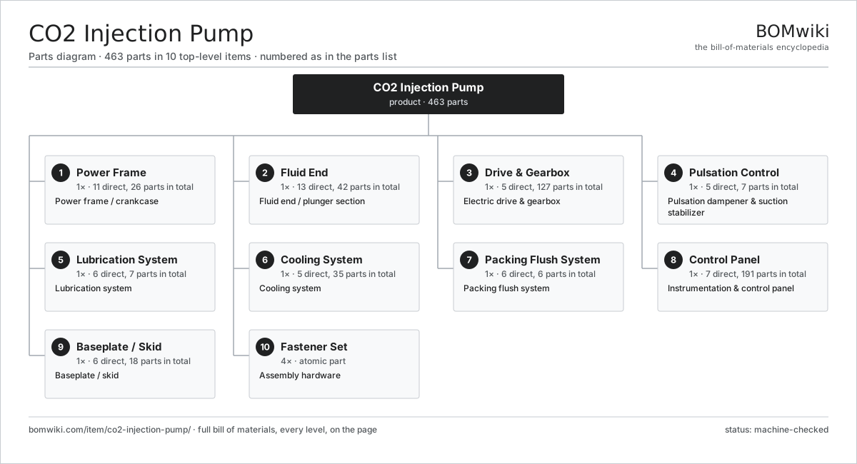
| # | Part | Qty | What it does |
|---|---|---|---|
| 1 | Power Frame 11 parts | 1× | Power frame / crankcase |
| 2 | Fluid End 13 parts | 1× | Fluid end / plunger section |
| 3 | Drive & Gearbox 5 parts | 1× | Electric drive & gearbox |
| 4 | Pulsation Control 5 parts | 1× | Pulsation dampener & suction stabilizer |
| 5 | Lubrication System 6 parts | 1× | Lubrication system |
| 6 | Cooling System 5 parts | 1× | Cooling system |
| 7 | Packing Flush System 6 parts | 1× | Packing flush system |
| 8 | Control Panel 7 parts | 1× | Instrumentation & control panel |
| 9 | Baseplate / Skid 6 parts | 1× | Baseplate / skid |
| 10 | Fastener Set | 4× | Assembly hardware |
3D model
No 3D model yet. Have a CAD file of this? Add a 3D model. STL renders right on this page; STEP, FreeCAD, and OpenSCAD sources are welcome too (openly licensed, like all 3D models on BOMwiki).
Build & assembly graph
expand / collapse · shared sub-assemblies converge · links to related products · est. labourTap an assembly to expand/collapse · tap a part to open it · use “Open page” for any node · drag to pan, scroll to zoom.
Bill of materials for CO2 Injection Pump
10 top-level lines · 105 rows shown · 463 parts total · indented to 3 levels| # | Item / sub-assembly | Part no. | Qty/assy | Ext. qty | Parts | Type |
|---|---|---|---|---|---|---|
| 1 | Power Frame 11 parts | co2-injection-pump-power-frame | 1× | 1 | 26 | assembly |
| 1.1 | Crankcase Casting | co2-injection-pump-crankcase | 1× | 1 | · | part |
| 1.2 | Crankshaft | co2-injection-pump-crankshaft | 1× | 1 | · | part |
| 1.3 | Connecting Rod 1 parts | co2-injection-pump-connecting-rod | 3× | 3 | · | part |
| 1.3.1 | Rod Bearing Insert | co2-injection-pump-rod-bearing | 1× | 3 | · | part |
| 1.4 | Crosshead | co2-injection-pump-crosshead | 3× | 3 | · | part |
| 1.5 | Crosshead Wrist Pin | co2-injection-pump-crosshead-pin | 3× | 3 | · | part |
| 1.6 | Crosshead Bore Liner | co2-injection-pump-crosshead-guide | 3× | 3 | · | part |
| 1.7 | Ball Bearing | ball-bearing | 2× | 2 | · | part |
| 1.8 | Pony Rod | co2-injection-pump-pony-rod | 3× | 3 | · | part |
| 1.9 | Oil Seal | oil-seal | 3× | 3 | · | part |
| 1.10 | Inspection Cover | co2-injection-pump-crankcase-cover | 2× | 2 | · | part |
| 1.11 | Fastener Set | fastener-set | 2× | 2 | · | part |
| 2 | Fluid End 13 parts | co2-injection-pump-fluid-end | 1× | 1 | 42 | assembly |
| 2.1 | Fluid-End Cylinder Block | co2-injection-pump-fluid-cylinder | 1× | 1 | · | part |
| 2.2 | Plunger | co2-injection-pump-plunger | 3× | 3 | · | part |
| 2.3 | Plunger Packing Set | co2-injection-pump-packing-set | 3× | 3 | · | part |
| 2.4 | Stuffing Box 1 parts | co2-injection-pump-stuffing-box | 3× | 3 | · | part |
| 2.4.1 | Lantern Ring | co2-injection-pump-lantern-ring | 1× | 3 | · | part |
| 2.5 | Suction Valve | co2-injection-pump-suction-valve | 3× | 3 | · | part |
| 2.6 | Discharge Valve | co2-injection-pump-discharge-valve | 3× | 3 | · | part |
| 2.7 | Valve Seat | co2-injection-pump-valve-seat | 6× | 6 | · | part |
| 2.8 | Valve Spring | co2-injection-pump-valve-spring | 6× | 6 | · | part |
| 2.9 | Valve Cover | co2-injection-pump-valve-cover | 6× | 6 | · | part |
| 2.10 | Suction Manifold | co2-injection-pump-suction-manifold | 1× | 1 | · | part |
| 2.11 | Discharge Manifold | co2-injection-pump-discharge-manifold | 1× | 1 | · | part |
| 2.12 | O-Ring Set | oring-set | 4× | 4 | · | part |
| 2.13 | Fastener Set | fastener-set | 2× | 2 | · | part |
| 3 | Drive & Gearbox 5 parts | co2-injection-pump-drive | 1× | 1 | 127 | assembly |
| 3.1 | Drive Motor 6 parts | co2-injection-pump-motor | 1× | 1 | 31 | assembly |
| 3.1.1 | Stator Assembly 3 parts + deeper › | stator-assembly | 1× | 1 | 3 | assembly |
| 3.1.2 | Rotor Assembly 4 parts + deeper › | rotor-assembly | 1× | 1 | 19 | assembly |
| 3.1.3 | Motor Frame | co2-injection-pump-motor-frame | 1× | 1 | · | part |
| 3.1.4 | Ball Bearing | ball-bearing | 2× | 2 | · | part |
| 3.1.5 | Motor Cooling Fan | co2-injection-pump-cooling-fan | 1× | 1 | · | part |
| 3.1.6 | Terminal Box 2 parts + deeper › | co2-injection-pump-terminal-box | 1× | 1 | · | part |
| 3.2 | Reduction Gearbox 5 parts | co2-injection-pump-gearbox | 1× | 1 | 11 | assembly |
| 3.2.1 | Helical Gear Pair | gear-pair | 2× | 2 | · | part |
| 3.2.2 | Gearbox Housing | gearbox-housing | 1× | 1 | · | part |
| 3.2.3 | Ball Bearing | ball-bearing | 4× | 4 | · | part |
| 3.2.4 | Oil Seal | oil-seal | 2× | 2 | · | part |
| 3.2.5 | Gearbox Shaft | co2-injection-pump-gearbox-shaft | 2× | 2 | · | part |
| 3.3 | Flexible Coupling | co2-injection-pump-coupling | 1× | 1 | · | part |
| 3.4 | Coupling Guard | co2-injection-pump-coupling-guard | 1× | 1 | · | part |
| 3.5 | Variable Frequency Drive 4 parts | co2-injection-pump-vfd | 1× | 1 | 83 | assembly |
| 3.5.1 | Bare PCB | pcb-bare | 1× | 1 | · | part |
| 3.5.2 | Power Supply | power-supply | 1× | 1 | · | part |
| 3.5.3 | SMD Passive (R/C/L) | smd-passives | 80× | 80 | · | part |
| 3.5.4 | IGBT Power Module | co2-injection-pump-igbt-module | 1× | 1 | · | part |
| 4 | Pulsation Control 5 parts | co2-injection-pump-pulsation-control | 1× | 1 | 7 | assembly |
| 4.1 | Discharge Pulsation Dampener | co2-injection-pump-discharge-dampener | 1× | 1 | · | part |
| 4.2 | Suction Stabilizer | co2-injection-pump-suction-stabilizer | 1× | 1 | · | part |
| 4.3 | Charged Bladder | co2-injection-pump-dampener-bladder | 2× | 2 | · | part |
| 4.4 | Discharge Relief Valve | co2-injection-pump-relief-valve | 1× | 1 | · | part |
| 4.5 | Pressure Sensor | pressure-sensor | 2× | 2 | · | part |
| 5 | Lubrication System 6 parts | co2-injection-pump-lube-system | 1× | 1 | 7 | assembly |
| 5.1 | Lube Oil Pump 2 parts | co2-injection-pump-lube-pump | 1× | 1 | · | part |
| 5.1.1 | Helical Gear Pair | gear-pair | 1× | 1 | · | part |
| 5.1.2 | Oil Seal | oil-seal | 1× | 1 | · | part |
| 5.2 | Oil Filter | co2-injection-pump-oil-filter | 1× | 1 | · | part |
| 5.3 | Oil Cooler | co2-injection-pump-oil-cooler | 1× | 1 | · | part |
| 5.4 | Plunger Lubricator | co2-injection-pump-plunger-lubricator | 1× | 1 | · | part |
| 5.5 | Level Gauge | co2-injection-pump-dipstick | 1× | 1 | · | part |
| 5.6 | Pressure Sensor | pressure-sensor | 1× | 1 | · | part |
| 6 | Cooling System 5 parts | co2-injection-pump-cooling-system | 1× | 1 | 35 | assembly |
| 6.1 | Coolant Pump 2 parts | co2-injection-pump-coolant-pump | 1× | 1 | · | part |
| 6.1.1 | Oil Seal | oil-seal | 1× | 1 | · | part |
| 6.1.2 | Ball Bearing | ball-bearing | 1× | 1 | · | part |
| 6.2 | Radiator | co2-injection-pump-radiator | 1× | 1 | · | part |
| 6.3 | Radiator Fan 2 parts | co2-injection-pump-fan | 1× | 1 | 25 | assembly |
| 6.3.1 | Servo Motor 4 parts + deeper › | servo-motor | 1× | 1 | 24 | assembly |
| 6.3.2 | Fan Blade | co2-injection-pump-fan-blade | 1× | 1 | · | part |
| 6.4 | Coolant Hose | co2-injection-pump-coolant-hose | 6× | 6 | · | part |
| 6.5 | Thermostat | co2-injection-pump-thermostat | 1× | 1 | · | part |
| 7 | Packing Flush System 6 parts | co2-injection-pump-flush-system | 1× | 1 | 6 | assembly |
| 7.1 | Flush Pump 1 parts | co2-injection-pump-flush-pump | 1× | 1 | · | part |
| 7.1.1 | Oil Seal | oil-seal | 1× | 1 | · | part |
| 7.2 | Flush Reservoir | co2-injection-pump-flush-tank | 1× | 1 | · | part |
| 7.3 | Flush Filter | co2-injection-pump-flush-filter | 1× | 1 | · | part |
| 7.4 | Flush Distribution Manifold | co2-injection-pump-flush-manifold | 1× | 1 | · | part |
| 7.5 | Leak-Off Collector | co2-injection-pump-leak-collector | 1× | 1 | · | part |
| 7.6 | Pressure Sensor | pressure-sensor | 1× | 1 | · | part |
| 8 | Control Panel 7 parts | co2-injection-pump-control-panel | 1× | 1 | 191 | assembly |
| 8.1 | PLC 4 parts | co2-injection-pump-plc | 1× | 1 | 116 | assembly |
| 8.1.1 | Bare PCB | pcb-bare | 1× | 1 | · | part |
| 8.1.2 | Microcontroller | mcu | 1× | 1 | · | part |
| 8.1.3 | Relay | relay | 4× | 4 | · | part |
| 8.1.4 | SMD Passive (R/C/L) | smd-passives | 110× | 110 | · | part |
| 8.2 | Operator HMI 3 parts | co2-injection-pump-hmi | 1× | 1 | 47 | assembly |
| 8.2.1 | Bare PCB | pcb-bare | 1× | 1 | · | part |
| 8.2.2 | LCD Panel | lcd-panel | 1× | 1 | · | part |
| 8.2.3 | SMD Passive (R/C/L) | smd-passives | 45× | 45 | · | part |
| 8.3 | Panel Enclosure | co2-injection-pump-panel-enclosure | 1× | 1 | · | part |
| 8.4 | CO2 Flow Meter | co2-injection-pump-flow-meter | 1× | 1 | · | part |
| 8.5 | Relay | relay | 8× | 8 | · | part |
| 8.6 | Wire Bundle | wire-bundle | 2× | 2 | · | part |
| 8.7 | Connector | connector | 16× | 16 | · | part |
| 9 | Baseplate / Skid 6 parts | co2-injection-pump-baseplate | 1× | 1 | 18 | assembly |
| 9.1 | Skid Frame | co2-injection-pump-skid-frame | 1× | 1 | · | part |
| 9.2 | Drip Pan | co2-injection-pump-drip-pan | 1× | 1 | · | part |
| 9.3 | Vibration Mount | co2-injection-pump-vibration-mount | 6× | 6 | · | part |
| 9.4 | Lifting Lug | co2-injection-pump-lifting-lug | 4× | 4 | · | part |
| 9.5 | Sheet Metal Panel | sheet-panel | 4× | 4 | · | part |
| 9.6 | Fastener Set | fastener-set | 2× | 2 | · | part |
| 10 | Fastener Set | fastener-set | 4× | 4 | · | part |
Related products
same domain, ranked by shared parts Wireline Logging Unit
189 parts · shares 19 with this page
Wireline Logging Unit
189 parts · shares 19 with this page
 Oilwell Cementing Unit
902 parts · shares 18 with this page
Oilwell Cementing Unit
902 parts · shares 18 with this page
 Drilling Mud Mixing System
135 parts · shares 16 with this page
Drilling Mud Mixing System
135 parts · shares 16 with this page
 Shale Shaker
201 parts · shares 15 with this page
Shale Shaker
201 parts · shares 15 with this page
 Amine Gas Sweetening Unit
3,543 parts · shares 15 with this page
Amine Gas Sweetening Unit
3,543 parts · shares 15 with this page
 Condensate Stabilizer Column
2,234 parts · shares 15 with this page
Condensate Stabilizer Column
2,234 parts · shares 15 with this page
Sourcing: possible vendors
Browse the supplier directory → Prices, MOQ, and lead times are algorithmic estimates, not quotes, and not claims about these companies. Company mappings are curated by keyword; est. price band $10k–$50M. How estimates work| Vendor | HQ | Specialty | MOQ | Lead time |
|---|---|---|---|---|
|
🇺🇸SLB
slb.com ↗
|
Houston, US | Oilfield services & equipment | made to order | 24–48 wks |
| halliburton.com ↗ | Houston, US | Oilfield services | made to order | 24–48 wks |
| bakerhughes.com ↗ | Houston, US | Energy technology | made to order | 24–48 wks |
|
🇺🇸NOV
nov.com ↗
|
Houston, US | Drilling equipment | made to order | 24–48 wks |
| technipfmc.com ↗ | London, GB | Subsea & surface systems | made to order | 24–48 wks |
1,081-word article