Shale Shaker
ProductOverview
A Shale Shaker is the first stage of solids control on a drilling rig. Drilling fluid, or mud, is pumped down the drill string and returns up the annulus carrying rock cuttings broken off by the bit. That mixture flows over the shaker, where vibrating screens hold back the solids and let the liquid mud fall through to be reused. A typical unit handles 600 to 900 gpm and runs continuously while the well is being drilled. If the shaker fails, cuttings reach the mud pumps and the rest of the solids-control train, so the equipment downstream of it depends on it working.
The machine has two parts that matter most: a Screen Basket that vibrates and a Skid Frame that does not. The basket carries the screens and the motors. The frame bolts to the mud tank and holds the basket on springs. Almost all the motion stays in the basket.
How it works
Separation happens by size. Mud and small cuttings pass through the openings in the Fine Separation Mesh; anything larger than the opening rides across the surface to the discharge end and falls off into a cuttings skip. The opening size sets the cut point, reported in microns under API RP 13C. A finer mesh removes smaller solids but passes less fluid before it floods, so the operator picks the finest screen that still keeps up with the flow rate.
Two Vibrator Motor motors drive the basket. Each one spins a Eccentric Shaft carrying Eccentric Weight masses at both ends. A single rotating weight would throw the basket in a circle; two motors turning in opposite directions cancel their side forces and leave a straight back-and-forth line of motion along the deck. That linear motion conveys cuttings uphill toward the discharge while the mud drains through. Running the pair out of phase, in elliptical or balanced-elliptical mode, is also used, but linear motion is the common case. The motors mount to a common Vibrator Mounting Beam so they shake the bed together.
The throw and the resulting g-force are set by rotating the outer plates of the eccentric weights against the inner plates. Most field shakers run between 7.0 and 7.5 g. Higher g dries the cuttings and speeds conveyance but shortens screen and bearing life, so the setting is a balance against panel cost.
Screens and the deck
The Screen Panel is the wear part. A panel is a pretensioned Panel Frame holding a fine cloth bonded over a heavier Coarse Backing Mesh backing. The backing carries the cuttings load and gives the fine cloth something to rest on; without it the fine wire would fatigue and tear in hours. The two cloths and the frame are joined by a Mesh Bonding Layer layer so they move as one. When a small hole opens up, the crew presses a Repair Plug into it rather than scrapping the whole panel.
Panels clamp into Screen Tension Rail rails along the deck and seat on Deck Support Rubber strips that cushion the mesh and seal the edges so mud cannot bypass the cloth. A three-panel deck lets the crew run a coarser screen at the feed end, where the cuttings load is heaviest, and a finer one toward the discharge.
Isolation, feed, and collection
The basket hangs on a Isolation Mount Set set of four Coil Spring springs. The springs let the basket vibrate freely while passing very little force into the frame and the tank. A Travel Snubber at each spring limits travel during start-up and shutdown, when the motors pass through the basket resonance and the swing grows for a moment.
Mud reaches the screen through the Possum Belly Feeder, a possum belly box at the back of the unit. The flow line dumps into the box, which fills and overflows a Distribution Weir so the mud spreads across the full width of the screen instead of jetting onto one spot and tearing it. A Bypass Dump Gate dumps flow around the screen during connections or while a panel is changed. Cleaned mud that passes the cloth drops into the Collection Pan and returns over a weir to the active tank. An Abrasion Liner and a Pan Wear Liner in AR400 wear plate protect the steel where solids strike it.
Controls and adjustment
A Control Panel in a flameproof enclosure starts the two motors through a Motor Starter soft starter on each, drives the angle actuator, and trips on overload or out-of-balance vibration sensed by a Pressure Sensor. The starters limit inrush and, where a drive is fitted, set the running frequency to tune the g-force without changing the eccentric weights.
The Deck Angle Adjuster tilts the basket about a Basket Pivot Pin using a Servo Motor and a Ball Screw. Raising the discharge end holds mud on the screen longer for a drier discharge and a higher fluid load; lowering it moves cuttings off faster. Deck angle usually runs between 0 and 5 degrees above horizontal and is changed while the unit runs.
Materials and variants
The structural steel is mostly ASTM A36 and A572 plate, with 42CrMo4 used for the eccentric shaft and pivot pins. Mesh is AISI 304 backing under AISI 316 fine cloth, since the fine wire sees both abrasion and corrosive mud. Wear surfaces use AR400 plate. Units range from single-deck shakers for lighter flow to dual and triple-deck designs and dryer shakers that follow a centrifuge. Larger rigs run two or three shakers in parallel off one flow line so the crew can change a screen on one while the others keep up with the well.
Shale Shaker parts and their functions
9 top-level parts · 201 parts in total · full bill of materials below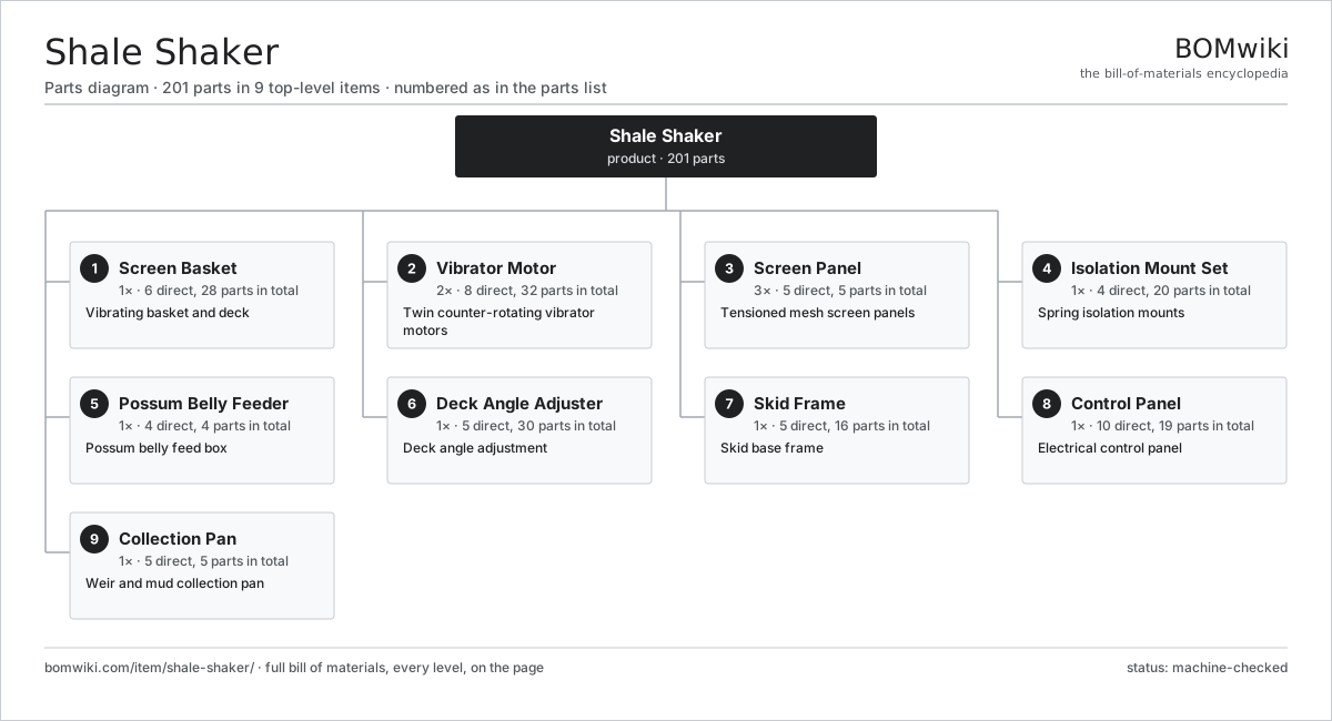
| # | Part | Qty | What it does |
|---|---|---|---|
| 1 | Screen Basket 6 parts | 1× | Vibrating basket and deck |
| 2 | Vibrator Motor 8 parts | 2× | Twin counter-rotating vibrator motors |
| 3 | Screen Panel 5 parts | 3× | Tensioned mesh screen panels |
| 4 | Isolation Mount Set 4 parts | 1× | Spring isolation mounts |
| 5 | Possum Belly Feeder 4 parts | 1× | Possum belly feed box |
| 6 | Deck Angle Adjuster 5 parts | 1× | Deck angle adjustment |
| 7 | Skid Frame 5 parts | 1× | Skid base frame |
| 8 | Control Panel 10 parts | 1× | Electrical control panel |
| 9 | Collection Pan 5 parts | 1× | Weir and mud collection pan |
3D model
No 3D model yet. Have a CAD file of this? Add a 3D model. STL renders right on this page; STEP, FreeCAD, and OpenSCAD sources are welcome too (openly licensed, like all 3D models on BOMwiki).
Build & assembly graph
expand / collapse · shared sub-assemblies converge · links to related products · est. labourTap an assembly to expand/collapse · tap a part to open it · use “Open page” for any node · drag to pan, scroll to zoom.
Bill of materials for Shale Shaker
9 top-level lines · 72 rows shown · 201 parts total · indented to 3 levels| # | Item / sub-assembly | Part no. | Qty/assy | Ext. qty | Parts | Type |
|---|---|---|---|---|---|---|
| 1 | Screen Basket 6 parts | shale-shaker-screen-basket | 1× | 1 | 28 | assembly |
| 1.1 | Basket Sidewall | shale-shaker-basket-sidewall | 2× | 2 | · | part |
| 1.2 | Deck Cross Member | shale-shaker-deck-crossmember | 5× | 5 | · | part |
| 1.3 | Screen Tension Rail | shale-shaker-tension-rail | 6× | 6 | · | part |
| 1.4 | Deck Support Rubber | shale-shaker-deck-rubber | 12× | 12 | · | part |
| 1.5 | Vibrator Mounting Beam | shale-shaker-vibrator-beam | 1× | 1 | · | part |
| 1.6 | Fastener Set | fastener-set | 2× | 2 | · | part |
| 2 | Vibrator Motor 8 parts | shale-shaker-vibrator-pair | 2× | 2 | 32 | assembly |
| 2.1 | Vibrator Housing | shale-shaker-vibrator-housing | 1× | 2 | · | part |
| 2.2 | Stator Assembly 3 parts | stator-assembly | 1× | 2 | 3 | assembly |
| 2.2.1 | Stator Core (laminations) | stator-core | 1× | 2 | · | part |
| 2.2.2 | Copper Winding | copper-winding | 1× | 2 | · | part |
| 2.2.3 | Slot Insulation | stator-insulation | 1× | 2 | · | part |
| 2.3 | Rotor Assembly 4 parts | rotor-assembly | 1× | 2 | 19 | assembly |
| 2.3.1 | Rotor Shaft | rotor-shaft | 1× | 2 | · | part |
| 2.3.2 | Rotor Core | rotor-core | 1× | 2 | · | part |
| 2.3.3 | Neodymium Magnet | neodymium-magnet | 16× | 32 | · | part |
| 2.3.4 | Ball Bearing | ball-bearing | 1× | 2 | · | part |
| 2.4 | Eccentric Shaft | shale-shaker-vibrator-shaft | 1× | 2 | · | part |
| 2.5 | Eccentric Weight | shale-shaker-eccentric-weight | 2× | 4 | · | part |
| 2.6 | Ball Bearing | ball-bearing | 2× | 4 | · | part |
| 2.7 | Oil Seal | oil-seal | 2× | 4 | · | part |
| 2.8 | Weight End Cover | shale-shaker-weight-cover | 2× | 4 | · | part |
| 3 | Screen Panel 5 parts | shale-shaker-screen-panel | 3× | 3 | 5 | assembly |
| 3.1 | Panel Frame | shale-shaker-screen-frame | 1× | 3 | · | part |
| 3.2 | Coarse Backing Mesh | shale-shaker-mesh-coarse | 1× | 3 | · | part |
| 3.3 | Fine Separation Mesh | shale-shaker-mesh-fine | 1× | 3 | · | part |
| 3.4 | Mesh Bonding Layer | shale-shaker-mesh-bonding | 1× | 3 | · | part |
| 3.5 | Repair Plug | shale-shaker-panel-plug | 1× | 3 | · | part |
| 4 | Isolation Mount Set 4 parts | shale-shaker-isolation-mount | 1× | 1 | 20 | assembly |
| 4.1 | Coil Spring | coil-spring | 4× | 4 | · | part |
| 4.2 | Spring Locating Cup | shale-shaker-spring-cup | 8× | 8 | · | part |
| 4.3 | Travel Snubber | shale-shaker-snubber | 4× | 4 | · | part |
| 4.4 | Spring Post | shale-shaker-spring-post | 4× | 4 | · | part |
| 5 | Possum Belly Feeder 4 parts | shale-shaker-feeder | 1× | 1 | 4 | assembly |
| 5.1 | Feed Box | shale-shaker-feeder-box | 1× | 1 | · | part |
| 5.2 | Distribution Weir | shale-shaker-feeder-weir | 1× | 1 | · | part |
| 5.3 | Bypass Dump Gate | shale-shaker-bypass-gate | 1× | 1 | · | part |
| 5.4 | Abrasion Liner | shale-shaker-feeder-liner | 1× | 1 | · | part |
| 6 | Deck Angle Adjuster 5 parts | shale-shaker-angle-adjust | 1× | 1 | 30 | assembly |
| 6.1 | Servo Motor 4 parts | servo-motor | 1× | 1 | 24 | assembly |
| 6.1.1 | Stator Assembly 3 parts + deeper › | stator-assembly | 1× | 1 | 3 | assembly |
| 6.1.2 | Rotor Assembly 4 parts + deeper › | rotor-assembly | 1× | 1 | 19 | assembly |
| 6.1.3 | Encoder | encoder | 1× | 1 | · | part |
| 6.1.4 | Motor Housing | motor-housing | 1× | 1 | · | part |
| 6.2 | Ball Screw | ball-screw | 1× | 1 | · | part |
| 6.3 | Basket Pivot Pin | shale-shaker-pivot-pin | 2× | 2 | · | part |
| 6.4 | Lift Bracket | shale-shaker-angle-bracket | 2× | 2 | · | part |
| 6.5 | Angle Indicator | shale-shaker-angle-indicator | 1× | 1 | · | part |
| 7 | Skid Frame 5 parts | shale-shaker-skid-frame | 1× | 1 | 16 | assembly |
| 7.1 | Skid Rail | shale-shaker-skid-rail | 2× | 2 | · | part |
| 7.2 | Skid Cross Beam | shale-shaker-skid-crossbeam | 4× | 4 | · | part |
| 7.3 | Mounting Foot | shale-shaker-mounting-foot | 4× | 4 | · | part |
| 7.4 | Lifting Lug | shale-shaker-lift-lug | 4× | 4 | · | part |
| 7.5 | Fastener Set | fastener-set | 2× | 2 | · | part |
| 8 | Control Panel 10 parts | shale-shaker-control-panel | 1× | 1 | 19 | assembly |
| 8.1 | Ex Enclosure | shale-shaker-enclosure | 1× | 1 | · | part |
| 8.2 | Motor Starter | shale-shaker-vfd | 2× | 2 | · | part |
| 8.3 | Bare PCB | pcb-bare | 1× | 1 | · | part |
| 8.4 | Microcontroller | mcu | 1× | 1 | · | part |
| 8.5 | SMD Passive (R/C/L) | smd-passives | 1× | 1 | · | part |
| 8.6 | Relay | relay | 4× | 4 | · | part |
| 8.7 | Pressure Sensor | pressure-sensor | 1× | 1 | · | part |
| 8.8 | Power Supply | power-supply | 1× | 1 | · | part |
| 8.9 | Wire Bundle | wire-bundle | 1× | 1 | · | part |
| 8.10 | Connector | connector | 6× | 6 | · | part |
| 9 | Collection Pan 5 parts | shale-shaker-collection-pan | 1× | 1 | 5 | assembly |
| 9.1 | Pan Body | shale-shaker-pan-body | 1× | 1 | · | part |
| 9.2 | Return Weir | shale-shaker-pan-weir | 1× | 1 | · | part |
| 9.3 | Pan Wear Liner | shale-shaker-pan-liner | 1× | 1 | · | part |
| 9.4 | Bypass Trough | shale-shaker-bypass-trough | 1× | 1 | · | part |
| 9.5 | O-Ring Set | oring-set | 1× | 1 | · | part |
Related products
same domain, ranked by shared parts Wireline Logging Unit
189 parts · shares 17 with this page
Wireline Logging Unit
189 parts · shares 17 with this page
 Sulfur Recovery Unit
206 parts · shares 15 with this page
Sulfur Recovery Unit
206 parts · shares 15 with this page
 Amine Gas Sweetening Unit
3,543 parts · shares 15 with this page
Amine Gas Sweetening Unit
3,543 parts · shares 15 with this page
 Condensate Stabilizer Column
2,234 parts · shares 15 with this page
CO2 Injection Pump
463 parts · shares 15 with this page
Condensate Stabilizer Column
2,234 parts · shares 15 with this page
CO2 Injection Pump
463 parts · shares 15 with this page
 Oilwell Cementing Unit
902 parts · shares 15 with this page
Oilwell Cementing Unit
902 parts · shares 15 with this page
Sourcing: possible vendors
Browse the supplier directory → Prices, MOQ, and lead times are algorithmic estimates, not quotes, and not claims about these companies. Company mappings are curated by keyword; est. price band $10k–$50M. How estimates work| Vendor | HQ | Specialty | MOQ | Lead time |
|---|---|---|---|---|
|
🇺🇸SLB
slb.com ↗
|
Houston, US | Oilfield services & equipment | made to order | 24–48 wks |
| halliburton.com ↗ | Houston, US | Oilfield services | made to order | 24–48 wks |
| bakerhughes.com ↗ | Houston, US | Energy technology | made to order | 24–48 wks |
|
🇺🇸NOV
nov.com ↗
|
Houston, US | Drilling equipment | made to order | 24–48 wks |
| technipfmc.com ↗ | London, GB | Subsea & surface systems | made to order | 24–48 wks |
988-word article