FCC Catalyst Regenerator
ProductOverview
The FCC catalyst regenerator is one half of the reactor-regenerator pair at the heart of a fluid catalytic cracking unit, the workhorse conversion process that turns heavy gas oil into gasoline and lighter products. Cracking happens in the riser reactor, where hot catalyst contacts vaporized feed for a few seconds. The reactions lay down a layer of carbon, called coke, on the catalyst, which kills its activity. The regenerator burns that coke off with air, restoring activity and, just as importantly, reheating the catalyst. The hot regenerated catalyst then carries the heat back to the riser to vaporize and crack the next feed. The regenerator is therefore both a combustor and the heat engine of the whole unit.
Catalyst flows continuously between the two vessels as a fluidized solid that behaves almost like a liquid. Spent coked catalyst enters the Regenerator Vessel, air burns the coke in a fluidized bed at around 1,300 F, internal cyclones recover the catalyst from the flue gas, and the clean hot catalyst returns to the riser. The Standpipes and Slide Valves system meters this circulation, and the Flue Gas System handles the hot combustion products, often recovering their energy.
How it works
Spent catalyst arrives from the reactor stripper down the Spent Catalyst Standpipe through the Spent Slide Valve into the regenerator. The Air Distribution System system, driven by the Main Air Blower, pushes combustion air up through the Air Distributor at the bottom, fluidizing the catalyst into a dense bubbling bed. Coke on the catalyst burns to carbon dioxide, carbon monoxide, and water, releasing heat that raises the bed to 1,250-1,400 F. The Dense Bed Section holds most of the combustion, while the Dilute Phase Section above gives catalyst room to fall back out of the rising gas.
Flue gas carries fine catalyst upward, so the Cyclone System cleans it. Two stages of cyclones, the Primary Cyclone and Secondary Cyclone, spin the catalyst to the wall and drop it back to the bed through the Cyclone Dipleg, each sealed at the bottom by a Dipleg Trickle Valve that lets catalyst out but blocks gas backflow. Cleaned flue gas collects in the Plenum Chamber and leaves the vessel. Regenerated catalyst leaves the bed down the Regenerated Catalyst Standpipe through the Regenerated Slide Valve, which is the key control: its opening sets the catalyst circulation rate and therefore the heat delivered to the riser and the reactor temperature.
Combustion modes and heat balance
Regenerators run in partial or full combustion. In full combustion, enough air is supplied to burn coke all the way to carbon dioxide, leaving little carbon monoxide and using a combustion promoter. In partial combustion, less air is used, the flue gas leaves rich in carbon monoxide, and a downstream CO Boiler completes the burn and recovers the heat as steam. The mode is chosen on the heat balance: the heat released burning coke must match the heat the catalyst carries to the riser to vaporize feed. When feed is heavy and lays down a lot of coke, the regenerator can overheat, so a Catalyst Cooler generates steam to pull excess heat out and protect the catalyst and refractory from temperatures that would destroy zeolite activity.
Flue gas and power recovery
Flue gas leaves hot and under pressure, carrying recoverable energy. Many units route it through a Power Recovery Expander, a turbine that extracts shaft power to help drive the air blower, cutting the unit's energy cost. Because catalyst fines would erode the expander blades, a Third-Stage Separator removes them first. Where there is no expander, the Orifice Chamber simply drops the pressure across staged orifices. The Flue Gas Slide Valve holds regenerator pressure, which must be balanced against reactor pressure to keep catalyst circulating correctly between the vessels.
Materials and refractory
The steel shell never sees full bed temperature because the Refractory System insulates it. An Insulating Refractory backing layer keeps the Vessel Shell Course cool, and a dense Erosion Refractory facing resists the sandblasting action of catalyst moving at high velocity, especially in the cyclones, air grid, and slide valves. Thin high-wear linings are held by Hexmesh Anchor mesh, and thicker linings by welded Refractory Anchor Stud anchors. Internals exposed to both heat and oxidation, like cyclones and the air distributor, are made from heat-resistant stainless such as 304H. Refractory condition sets turnaround scope, since spalling or erosion exposes steel to temperatures it cannot survive.
Control and catalyst management
The Instrument Package runs the regenerator. Bed thermocouples and the Oxygen Analyzer control combustion air so coke burns completely without runaway afterburn in the dilute phase, which the CO Analyzer watches for. The two slide valves set catalyst circulation and reactor temperature, with the Control Panel holding the interlocks that trip the unit safely on loss of air or circulation. Over time catalyst loses activity and accumulates metals from the feed, so the Catalyst Handling System system continuously adds fresh catalyst and withdraws equilibrium catalyst to hold inventory, activity, and particle size in the right range. Stable circulation, complete combustion, and intact refractory together set how hard and how long the FCC unit can run.
FCC Catalyst Regenerator parts and their functions
9 top-level parts · 175 parts in total · full bill of materials below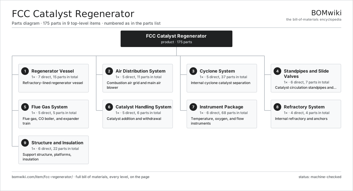
| # | Part | Qty | What it does |
|---|---|---|---|
| 1 | Regenerator Vessel 7 parts | 1× | Refractory-lined regenerator vessel |
| 2 | Air Distribution System 5 parts | 1× | Combustion air grid and main air blower |
| 3 | Cyclone System 5 parts | 1× | Internal cyclone catalyst separation |
| 4 | Standpipes and Slide Valves 6 parts | 1× | Catalyst circulation standpipes and slide valves |
| 5 | Flue Gas System 5 parts | 1× | Flue gas, CO boiler, and expander train |
| 6 | Catalyst Handling System 5 parts | 1× | Catalyst addition and withdrawal |
| 7 | Instrument Package 6 parts | 1× | Temperature, oxygen, and flow instruments |
| 8 | Refractory System 4 parts | 1× | Internal refractory and anchors |
| 9 | Structure and Insulation 6 parts | 1× | Support structure, platforms, insulation |
3D model
No 3D model yet. Have a CAD file of this? Add a 3D model. STL renders right on this page; STEP, FreeCAD, and OpenSCAD sources are welcome too (openly licensed, like all 3D models on BOMwiki).
Build & assembly graph
expand / collapse · shared sub-assemblies converge · links to related products · est. labourTap an assembly to expand/collapse · tap a part to open it · use “Open page” for any node · drag to pan, scroll to zoom.
Bill of materials for FCC Catalyst Regenerator
9 top-level lines · 73 rows shown · 175 parts total · indented to 3 levels| # | Item / sub-assembly | Part no. | Qty/assy | Ext. qty | Parts | Type |
|---|---|---|---|---|---|---|
| 1 | Regenerator Vessel 7 parts | fcc-regen-vessel | 1× | 1 | 15 | assembly |
| 1.1 | Vessel Shell Course | fcc-vessel-shell | 4× | 4 | · | part |
| 1.2 | Vessel Head | fcc-vessel-head | 2× | 2 | · | part |
| 1.3 | Dense Bed Section | fcc-dense-bed-zone | 1× | 1 | · | part |
| 1.4 | Dilute Phase Section | fcc-dilute-phase-zone | 1× | 1 | · | part |
| 1.5 | Catalyst Cooler 4 parts | fcc-catalyst-cooler | 1× | 1 | 4 | assembly |
| 1.5.1 | Cooler Tube Bundle | fcc-cooler-tube-bundle | 1× | 1 | · | part |
| 1.5.2 | Cooler Shell | fcc-cooler-shell | 1× | 1 | · | part |
| 1.5.3 | Steam Drum | fcc-cooler-steam-drum | 1× | 1 | · | part |
| 1.5.4 | Cooler Fluidizing Air | fcc-cooler-fluidizing-air | 1× | 1 | · | part |
| 1.6 | Nozzle Set | fcc-nozzle-set | 1× | 1 | · | part |
| 1.7 | Manway | fcc-manway | 2× | 2 | · | part |
| 2 | Air Distribution System 5 parts | fcc-air-distribution | 1× | 1 | 11 | assembly |
| 2.1 | Main Air Blower 5 parts | fcc-main-air-blower | 1× | 1 | 7 | assembly |
| 2.1.1 | Blower Rotor | fcc-blower-rotor | 1× | 1 | · | part |
| 2.1.2 | Blower Casing | fcc-blower-casing | 1× | 1 | · | part |
| 2.1.3 | Blower Bearing | fcc-blower-bearing | 2× | 2 | · | part |
| 2.1.4 | Blower Drive | fcc-blower-drive | 1× | 1 | · | part |
| 2.1.5 | Blower Seal | fcc-blower-seal | 2× | 2 | · | part |
| 2.2 | Air Distributor | fcc-air-distributor | 1× | 1 | · | part |
| 2.3 | Air Ring | fcc-air-ring | 1× | 1 | · | part |
| 2.4 | Air Control Valve | fcc-air-control-valve | 1× | 1 | · | part |
| 2.5 | Air Check Valve | fcc-air-check-valve | 1× | 1 | · | part |
| 3 | Cyclone System 5 parts | fcc-cyclone-system | 1× | 1 | 37 | assembly |
| 3.1 | Primary Cyclone | fcc-primary-cyclone | 6× | 6 | · | part |
| 3.2 | Secondary Cyclone | fcc-secondary-cyclone | 6× | 6 | · | part |
| 3.3 | Cyclone Dipleg | fcc-cyclone-dipleg | 12× | 12 | · | part |
| 3.4 | Dipleg Trickle Valve | fcc-dipleg-flapper | 12× | 12 | · | part |
| 3.5 | Plenum Chamber | fcc-plenum-chamber | 1× | 1 | · | part |
| 4 | Standpipes and Slide Valves 6 parts | fcc-standpipe-slide | 1× | 1 | 7 | assembly |
| 4.1 | Spent Catalyst Standpipe | fcc-spent-standpipe | 1× | 1 | · | part |
| 4.2 | Regenerated Catalyst Standpipe | fcc-regen-standpipe | 1× | 1 | · | part |
| 4.3 | Spent Slide Valve | fcc-spent-slide-valve | 1× | 1 | · | part |
| 4.4 | Regenerated Slide Valve | fcc-regen-slide-valve | 1× | 1 | · | part |
| 4.5 | Aeration Taps | fcc-aeration-taps | 1× | 1 | · | part |
| 4.6 | Slide Valve Actuator | fcc-slide-valve-actuator | 2× | 2 | · | part |
| 5 | Flue Gas System 5 parts | fcc-flue-gas-system | 1× | 1 | 5 | assembly |
| 5.1 | Power Recovery Expander | fcc-power-expander | 1× | 1 | · | part |
| 5.2 | Third-Stage Separator | fcc-third-stage-separator | 1× | 1 | · | part |
| 5.3 | CO Boiler | fcc-co-boiler | 1× | 1 | · | part |
| 5.4 | Flue Gas Slide Valve | fcc-flue-slide-valve | 1× | 1 | · | part |
| 5.5 | Orifice Chamber | fcc-orifice-chamber | 1× | 1 | · | part |
| 6 | Catalyst Handling System 5 parts | fcc-catalyst-handling | 1× | 1 | 6 | assembly |
| 6.1 | Fresh Catalyst Hopper | fcc-fresh-catalyst-hopper | 1× | 1 | · | part |
| 6.2 | Equilibrium Catalyst Hopper | fcc-spent-catalyst-hopper | 1× | 1 | · | part |
| 6.3 | Catalyst Loader | fcc-catalyst-loader | 1× | 1 | · | part |
| 6.4 | Transfer Line | fcc-transfer-line | 1× | 1 | · | part |
| 6.5 | Catalyst Valve | fcc-catalyst-valve | 2× | 2 | · | part |
| 7 | Instrument Package 6 parts | fcc-instrument-package | 1× | 1 | 68 | assembly |
| 7.1 | Bed Thermocouple | fcc-bed-thermocouple | 8× | 8 | · | part |
| 7.2 | Oxygen Analyzer | fcc-oxygen-analyzer | 2× | 2 | · | part |
| 7.3 | CO Analyzer | fcc-co-analyzer | 1× | 1 | · | part |
| 7.4 | Pressure Sensor | pressure-sensor | 6× | 6 | · | part |
| 7.5 | Flow Meter | fcc-flow-meter | 3× | 3 | · | part |
| 7.6 | Control Panel 6 parts | fcc-control-panel | 1× | 1 | 48 | assembly |
| 7.6.1 | Bare PCB | pcb-bare | 2× | 2 | · | part |
| 7.6.2 | Microcontroller | mcu | 2× | 2 | · | part |
| 7.6.3 | Relay | relay | 12× | 12 | · | part |
| 7.6.4 | Power Supply | power-supply | 1× | 1 | · | part |
| 7.6.5 | Connector | connector | 30× | 30 | · | part |
| 7.6.6 | Wire Bundle | wire-bundle | 1× | 1 | · | part |
| 8 | Refractory System 4 parts | fcc-refractory-system | 1× | 1 | 4 | assembly |
| 8.1 | Insulating Refractory | fcc-insulating-refractory | 1× | 1 | · | part |
| 8.2 | Erosion Refractory | fcc-erosion-refractory | 1× | 1 | · | part |
| 8.3 | Hexmesh Anchor | fcc-hexmesh-anchor | 1× | 1 | · | part |
| 8.4 | Refractory Anchor Stud | fcc-refractory-anchor-stud | 1× | 1 | · | part |
| 9 | Structure and Insulation 6 parts | fcc-structure | 1× | 1 | 22 | assembly |
| 9.1 | Support Skirt | fcc-support-skirt | 1× | 1 | · | part |
| 9.2 | Structure Steel | fcc-structure-steel | 1× | 1 | · | part |
| 9.3 | Access Platform | fcc-platform | 6× | 6 | · | part |
| 9.4 | External Insulation | fcc-external-insulation | 1× | 1 | · | part |
| 9.5 | Sheet Metal Panel | sheet-panel | 12× | 12 | · | part |
| 9.6 | Fastener Set | fastener-set | 1× | 1 | · | part |
Related products
same domain, ranked by shared parts Amine Gas Sweetening Unit
3,543 parts · shares 2 with this page
CO2 Injection Pump
463 parts · shares 2 with this page
Amine Gas Sweetening Unit
3,543 parts · shares 2 with this page
CO2 Injection Pump
463 parts · shares 2 with this page
 Condensate Stabilizer Column
2,234 parts · shares 2 with this page
Condensate Stabilizer Column
2,234 parts · shares 2 with this page
 Delayed Coker Drum
208 parts · shares 2 with this page
Delayed Coker Drum
208 parts · shares 2 with this page
 Drilling Mud Degasser
154 parts · shares 2 with this page
Drilling Mud Degasser
154 parts · shares 2 with this page
 Drilling Mud Mixing System
135 parts · shares 2 with this page
Drilling Mud Mixing System
135 parts · shares 2 with this page
Sourcing: possible vendors
Browse the supplier directory → Prices, MOQ, and lead times are algorithmic estimates, not quotes, and not claims about these companies. Company mappings are curated by keyword; est. price band $10k–$50M. How estimates work| Vendor | HQ | Specialty | MOQ | Lead time |
|---|---|---|---|---|
|
🇺🇸SLB
slb.com ↗
|
Houston, US | Oilfield services & equipment | made to order | 24–48 wks |
| halliburton.com ↗ | Houston, US | Oilfield services | made to order | 24–48 wks |
| bakerhughes.com ↗ | Houston, US | Energy technology | made to order | 24–48 wks |
|
🇺🇸NOV
nov.com ↗
|
Houston, US | Drilling equipment | made to order | 24–48 wks |
| technipfmc.com ↗ | London, GB | Subsea & surface systems | made to order | 24–48 wks |
889-word article