Pipeline Pig Receiver
ProductOverview
A pipeline pig receiver, also called a receiving trap, is the fitting at the end of a pipeline run that captures a pig after it has traveled the length of the line. A pig is a device pushed through the pipe by the flow itself, used to clean the wall, separate fluid batches, or carry inspection sensors. The receiver gives the pig somewhere to stop, then lets an operator isolate that section, bleed it down, and open it to pull the pig out, all without shutting the pipeline.
The trap is a larger-diameter barrel teed off the main line. When a pig arrives it slides into the oversized barrel, where the flow drops and the pig parks. The geometry, valving and venting all exist to do one job safely: capture the pig under full line pressure, then make the barrel safe to open by hand.
Barrel and closure
The Barrel Assembly is the pressure-containing heart of the trap. A Major Barrel section, one or two pipe sizes larger than the line, gives the pig room to settle out of the flow. At the open end is the Quick-Opening Closure, the feature that makes a trap a trap: instead of unbolting a flange, an operator swings open a Closure Door held shut by a bayonet Locking Ring. The door rides on a Closure Hinge and is sealed by a Closure Seal elastomer ring. Because opening a barrel that still holds pressure is lethal, a Pressure-Warning Interlock interlock prevents the closure from being unlocked until the barrel is vented. A Handling Davit takes the weight of the heavy door as it swings clear.
Reducer and pig stop
Between the big barrel and the running pipeline sits the Eccentric Reducer. A Reducer Body eccentric reducer steps the oversized barrel down to the line bore through a Neck Pipe, with the eccentric shape keeping the bottom flat so the pig and any liquids run along one level. A Pig Stop bar holds the captured pig back in the barrel so it cannot drift into the reducer throat and jam. The eccentric reducer is standard on traps because a concentric one would leave a step the pig has to climb and a low pocket where liquid collects.
Valves and flow routing
The Trap Valve Set routes the flow that captures the pig and then isolates the barrel. The main Trap Valve, a full-bore API 6D valve, separates the barrel from the live pipeline once the pig is caught. A Kicker Valve introduces flow behind the pig to seat it firmly in the barrel, and a Bypass Valve keeps the pipeline flowing through the station while the trap is being worked. Each valve carries a Valve Actuator for operation. Routing flow this way is what lets the receiver catch a pig and be opened while gas keeps moving down the line.
Detection, venting and instruments
The operator needs to know the pig has actually arrived, so a Pig Signaler sits on the barrel. A passing pig pushes a Trigger Pin that a Magnetic Switch senses and an Indicator Flag shows locally, confirming the pig is in the trap before anyone touches the closure.
Once the pig is captured and the barrel isolated, the Drain & Vent System system makes it safe to open. A Vent Valve sends barrel gas to flare or a safe area, a Drain Valve empties any liquid through the Drain Piping, and a relief valve protects the barrel from overpressure. The Instrument Set confirms the state of the barrel: pressure transmitters and a local Pressure Gauge read the pressure, and a Bleed Indicator gives the positive confirmation that the barrel has reached zero before the closure is opened.
Structure and use
The trap is heavy and lives outdoors, so the Support Structure cradles it. A pair of Saddle Support supports carries the barrel to its foundation, a Access Platform gives crews safe access to the closure and valves, and a Handling Rail helps slide a long, heavy pig out of the barrel once the door is open.
Receivers are sized to the pipeline, from small gathering lines a few inches across to large transmission lines up to four feet in diameter. Liquid pipelines built to ASME B31.4 and gas pipelines built to B31.8 use the same trap concept, with the barrel design pressure matched to the line it serves. Every pipeline that runs cleaning or inspection pigs needs a receiver at the downstream end and a matching launcher at the upstream end, and the two are mirror images of each other.
Pipeline Pig Receiver parts and their functions
7 top-level parts · 38 parts in total · full bill of materials below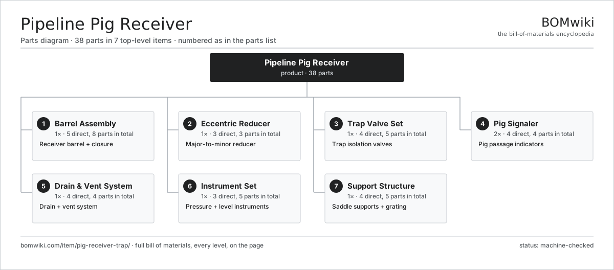
| # | Part | Qty | What it does |
|---|---|---|---|
| 1 | Barrel Assembly 5 parts | 1× | Receiver barrel + closure |
| 2 | Eccentric Reducer 3 parts | 1× | Major-to-minor reducer |
| 3 | Trap Valve Set 4 parts | 1× | Trap isolation valves |
| 4 | Pig Signaler 4 parts | 2× | Pig passage indicators |
| 5 | Drain & Vent System 4 parts | 1× | Drain + vent system |
| 6 | Instrument Set 3 parts | 1× | Pressure + level instruments |
| 7 | Support Structure 4 parts | 1× | Saddle supports + grating |
3D model
No 3D model yet. Have a CAD file of this? Add a 3D model. STL renders right on this page; STEP, FreeCAD, and OpenSCAD sources are welcome too (openly licensed, like all 3D models on BOMwiki).
Build & assembly graph
expand / collapse · shared sub-assemblies converge · links to related products · est. labourTap an assembly to expand/collapse · tap a part to open it · use “Open page” for any node · drag to pan, scroll to zoom.
Bill of materials for Pipeline Pig Receiver
7 top-level lines · 38 rows shown · 38 parts total · indented to 3 levels| # | Item / sub-assembly | Part no. | Qty/assy | Ext. qty | Parts | Type |
|---|---|---|---|---|---|---|
| 1 | Barrel Assembly 5 parts | prt-barrel-assembly | 1× | 1 | 8 | assembly |
| 1.1 | Major Barrel | prt-major-barrel | 1× | 1 | · | part |
| 1.2 | Quick-Opening Closure 4 parts | prt-quick-closure | 1× | 1 | 4 | assembly |
| 1.2.1 | Closure Door | prt-closure-door | 1× | 1 | · | part |
| 1.2.2 | Locking Ring | prt-locking-ring | 1× | 1 | · | part |
| 1.2.3 | Closure Hinge | prt-hinge | 1× | 1 | · | part |
| 1.2.4 | Pressure-Warning Interlock | prt-pressure-warning | 1× | 1 | · | part |
| 1.3 | Closure Seal | prt-closure-seal | 1× | 1 | · | part |
| 1.4 | End Flange | prt-end-flange | 1× | 1 | · | part |
| 1.5 | Handling Davit | prt-davit | 1× | 1 | · | part |
| 2 | Eccentric Reducer 3 parts | prt-reducer | 1× | 1 | 3 | assembly |
| 2.1 | Reducer Body | prt-reducer-body | 1× | 1 | · | part |
| 2.2 | Pig Stop | prt-pig-stop | 1× | 1 | · | part |
| 2.3 | Neck Pipe | prt-neck-pipe | 1× | 1 | · | part |
| 3 | Trap Valve Set 4 parts | prt-valve-set | 1× | 1 | 5 | assembly |
| 3.1 | Trap Valve | prt-trap-valve | 1× | 1 | · | part |
| 3.2 | Kicker Valve | prt-kicker-valve | 1× | 1 | · | part |
| 3.3 | Bypass Valve | prt-bypass-valve | 1× | 1 | · | part |
| 3.4 | Valve Actuator | prt-actuator | 2× | 2 | · | part |
| 4 | Pig Signaler 4 parts | prt-pig-signaler | 2× | 2 | 4 | assembly |
| 4.1 | Trigger Pin | prt-trigger-pin | 1× | 2 | · | part |
| 4.2 | Magnetic Switch | prt-magnetic-switch | 1× | 2 | · | part |
| 4.3 | Indicator Flag | prt-indicator-flag | 1× | 2 | · | part |
| 4.4 | Bare PCB | pcb-bare | 1× | 2 | · | part |
| 5 | Drain & Vent System 4 parts | prt-drain-vent | 1× | 1 | 4 | assembly |
| 5.1 | Vent Valve | prt-vent-valve | 1× | 1 | · | part |
| 5.2 | Drain Valve | prt-drain-valve | 1× | 1 | · | part |
| 5.3 | Drain Piping | prt-drain-piping | 1× | 1 | · | part |
| 5.4 | Relief Valve | prt-relief-valve | 1× | 1 | · | part |
| 6 | Instrument Set 3 parts | prt-instrument-set | 1× | 1 | 5 | assembly |
| 6.1 | Pressure Sensor | pressure-sensor | 2× | 2 | · | part |
| 6.2 | Pressure Gauge | prt-pressure-gauge | 2× | 2 | · | part |
| 6.3 | Bleed Indicator | prt-bleed-indicator | 1× | 1 | · | part |
| 7 | Support Structure 4 parts | prt-support-structure | 1× | 1 | 5 | assembly |
| 7.1 | Saddle Support | prt-saddle | 2× | 2 | · | part |
| 7.2 | Access Platform | prt-platform | 1× | 1 | · | part |
| 7.3 | Handling Rail | prt-handling-rail | 1× | 1 | · | part |
| 7.4 | Fastener Set | fastener-set | 1× | 1 | · | part |
Sourcing: possible vendors
Browse the supplier directory → Prices, MOQ, and lead times are algorithmic estimates, not quotes, and not claims about these companies. Company mappings are curated by keyword; est. price band $10k–$50M. How estimates work| Vendor | HQ | Specialty | MOQ | Lead time |
|---|---|---|---|---|
|
🇺🇸SLB
slb.com ↗
|
Houston, US | Oilfield services & equipment | made to order | 24–48 wks |
| halliburton.com ↗ | Houston, US | Oilfield services | made to order | 24–48 wks |
| bakerhughes.com ↗ | Houston, US | Energy technology | made to order | 24–48 wks |
|
🇺🇸NOV
nov.com ↗
|
Houston, US | Drilling equipment | made to order | 24–48 wks |
| technipfmc.com ↗ | London, GB | Subsea & surface systems | made to order | 24–48 wks |
789-word article