Coiled Tubing Unit
ProductOverview
A coiled tubing unit runs a continuous, jointless string of small-diameter steel tubing into a live well without killing it. Unlike jointed pipe, the tubing comes off a single large reel, so the unit can push it in and pull it out quickly and under pressure. That makes it the workhorse of well intervention: cleaning out fill, milling scale, placing chemicals, nitrogen-lifting a dead well, logging, and fishing for stuck tools. The whole spread, reel, injector, well-control stack and power supply, is mobile so it can rig up over a wellhead and move on.
Because the well stays pressurized throughout, the unit is built around a chain of pressure barriers between the open atmosphere and the formation.
How it works
The tubing is stored on the Tubing Reel, whose level wind spools it evenly and whose hydraulic motor pays it out under controlled tension. It feeds over the Gooseneck Guide, a roller arch that bends it down into the Injector Head. There two opposed gripper chains clamp the tubing and drive it into or out of the well, with a load cell reading tubing weight so the operator knows the downhole force.
Below the injector, the Stuffing Box packs around the moving tubing to hold well pressure, and the BOP Stack sits beneath it as the well-control barrier, with four rams that can grip, seal or shear the tubing in an emergency. All of these functions are powered from the Hydraulic Power Pack, whose hydraulic pump and valve bank feed the reel, injector and rams.
The operator works from the Control Cabin, driving the injector and reel with joysticks while a data display shows depth, weight, speed and pressures. The complete spread is carried on the Trailer / Skid, which levels and anchors the unit at the wellsite.
Coiled Tubing Unit parts and their functions
8 top-level parts · 190 parts in total · full bill of materials below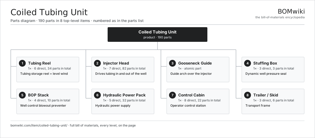
| # | Part | Qty | What it does |
|---|---|---|---|
| 1 | Tubing Reel 6 parts | 1× | Tubing storage reel + level wind |
| 2 | Injector Head 7 parts | 1× | Drives tubing in and out of the well |
| 3 | Gooseneck Guide | 1× | Guide arch over the injector |
| 4 | Stuffing Box 3 parts | 1× | Dynamic well pressure seal |
| 5 | BOP Stack 4 parts | 1× | Well control blowout preventer |
| 6 | Hydraulic Power Pack 5 parts | 1× | Hydraulic power supply |
| 7 | Control Cabin 8 parts | 1× | Operator control station |
| 8 | Trailer / Skid 3 parts | 1× | Transport frame |
3D model
No 3D model yet. Have a CAD file of this? Add a 3D model. STL renders right on this page; STEP, FreeCAD, and OpenSCAD sources are welcome too (openly licensed, like all 3D models on BOMwiki).
Build & assembly graph
expand / collapse · shared sub-assemblies converge · links to related products · est. labourTap an assembly to expand/collapse · tap a part to open it · use “Open page” for any node · drag to pan, scroll to zoom.
Bill of materials for Coiled Tubing Unit
8 top-level lines · 64 rows shown · 190 parts total · indented to 3 levels| # | Item / sub-assembly | Part no. | Qty/assy | Ext. qty | Parts | Type |
|---|---|---|---|---|---|---|
| 1 | Tubing Reel 6 parts | ctu-reel | 1× | 1 | 34 | assembly |
| 1.1 | Reel Drum | ctu-reel-drum | 1× | 1 | · | part |
| 1.2 | Level Wind 3 parts | ctu-level-wind | 1× | 1 | 4 | assembly |
| 1.2.1 | Level Wind Lead Screw | ctu-level-wind-screw | 1× | 1 | · | part |
| 1.2.2 | Level Wind Roller | ctu-level-wind-roller | 2× | 2 | · | part |
| 1.2.3 | Helical Gear Pair | gear-pair | 1× | 1 | · | part |
| 1.3 | Reel Motor 4 parts | ctu-reel-motor | 1× | 1 | 25 | assembly |
| 1.3.1 | Stator Assembly 3 parts + deeper › | stator-assembly | 1× | 1 | 3 | assembly |
| 1.3.2 | Rotor Assembly 4 parts + deeper › | rotor-assembly | 1× | 1 | 19 | assembly |
| 1.3.3 | Motor Housing | motor-housing | 1× | 1 | · | part |
| 1.3.4 | Ball Bearing | ball-bearing | 2× | 2 | · | part |
| 1.4 | Reel Swivel | ctu-reel-swivel | 1× | 1 | · | part |
| 1.5 | Helical Gear Pair | gear-pair | 1× | 1 | · | part |
| 1.6 | Ball Bearing | ball-bearing | 2× | 2 | · | part |
| 2 | Injector Head 7 parts | ctu-injector-head | 1× | 1 | 82 | assembly |
| 2.1 | Gripper Chain | ctu-gripper-chain | 2× | 2 | · | part |
| 2.2 | Gripper Block | ctu-gripper-block | 24× | 24 | · | part |
| 2.3 | Injector Drive Motor 4 parts | ctu-injector-motor | 2× | 2 | 25 | assembly |
| 2.3.1 | Stator Assembly 3 parts + deeper › | stator-assembly | 1× | 2 | 3 | assembly |
| 2.3.2 | Rotor Assembly 4 parts + deeper › | rotor-assembly | 1× | 2 | 19 | assembly |
| 2.3.3 | Motor Housing | motor-housing | 1× | 2 | · | part |
| 2.3.4 | Ball Bearing | ball-bearing | 2× | 4 | · | part |
| 2.4 | Gearbox Housing | gearbox-housing | 1× | 1 | · | part |
| 2.5 | Helical Gear Pair | gear-pair | 2× | 2 | · | part |
| 2.6 | Load Cell | ctu-load-cell | 1× | 1 | · | part |
| 2.7 | Traction Cylinder | ctu-traction-cylinder | 2× | 2 | · | part |
| 3 | Gooseneck Guide | ctu-gooseneck | 1× | 1 | · | part |
| 4 | Stuffing Box 3 parts | ctu-stuffing-box | 1× | 1 | 3 | assembly |
| 4.1 | Stuffing Box Body | ctu-stuffing-body | 1× | 1 | · | part |
| 4.2 | Stuffing Box Packing | ctu-stuffing-packing | 1× | 1 | · | part |
| 4.3 | O-Ring Set | oring-set | 1× | 1 | · | part |
| 5 | BOP Stack 4 parts | ctu-bop-stack | 1× | 1 | 10 | assembly |
| 5.1 | BOP Body | ctu-bop-body | 1× | 1 | · | part |
| 5.2 | BOP Ram | ctu-bop-ram | 4× | 4 | · | part |
| 5.3 | BOP Ram Actuator | ctu-bop-actuator | 4× | 4 | · | part |
| 5.4 | O-Ring Set | oring-set | 1× | 1 | · | part |
| 6 | Hydraulic Power Pack 5 parts | ctu-power-pack | 1× | 1 | 32 | assembly |
| 6.1 | Pump Drive Motor 4 parts | ctu-hydraulic-pump-motor | 1× | 1 | 25 | assembly |
| 6.1.1 | Stator Assembly 3 parts + deeper › | stator-assembly | 1× | 1 | 3 | assembly |
| 6.1.2 | Rotor Assembly 4 parts + deeper › | rotor-assembly | 1× | 1 | 19 | assembly |
| 6.1.3 | Motor Housing | motor-housing | 1× | 1 | · | part |
| 6.1.4 | Ball Bearing | ball-bearing | 2× | 2 | · | part |
| 6.2 | Hydraulic Pump | ctu-hydraulic-pump | 1× | 1 | · | part |
| 6.3 | Control Valve Bank | ctu-control-valve-bank | 1× | 1 | · | part |
| 6.4 | Hydraulic Reservoir | ctu-oil-reservoir | 1× | 1 | · | part |
| 6.5 | Relay | relay | 4× | 4 | · | part |
| 7 | Control Cabin 8 parts | ctu-control-cabin | 1× | 1 | 22 | assembly |
| 7.1 | Seat Assembly 5 parts | seat-assembly | 1× | 1 | 7 | assembly |
| 7.1.1 | Seat Frame | seat-frame | 1× | 1 | · | part |
| 7.1.2 | Seat Foam | seat-foam | 2× | 2 | · | part |
| 7.1.3 | Seat Cover | seat-cover | 1× | 1 | · | part |
| 7.1.4 | Seat Motor | seat-motor | 2× | 2 | · | part |
| 7.1.5 | Seat Heater Mat | seat-heater | 1× | 1 | · | part |
| 7.2 | LCD Panel | lcd-panel | 1× | 1 | · | part |
| 7.3 | Touch Digitizer | touch-digitizer | 1× | 1 | · | part |
| 7.4 | Bare PCB | pcb-bare | 1× | 1 | · | part |
| 7.5 | Microcontroller | mcu | 1× | 1 | · | part |
| 7.6 | Control Joystick | ctu-joystick | 2× | 2 | · | part |
| 7.7 | Wire Bundle | wire-bundle | 1× | 1 | · | part |
| 7.8 | Connector | connector | 8× | 8 | · | part |
| 8 | Trailer / Skid 3 parts | ctu-trailer-skid | 1× | 1 | 6 | assembly |
| 8.1 | Frame Rails | ctu-frame-rails | 1× | 1 | · | part |
| 8.2 | Outrigger | ctu-outriggers | 4× | 4 | · | part |
| 8.3 | Fastener Set | fastener-set | 1× | 1 | · | part |
Something wrong in this list? Report a problem with this BOM.
Related products
same domain, ranked by shared parts Deepwater Drillship
891,301 parts · shares 16 with this page
 Iron Roughneck
104 parts · shares 4 with this page
CO2 Injection Pump
463 parts · shares 13 with this page
 Wireline Logging Unit
189 parts · shares 13 with this page
 Drilling Top Drive
181 parts · shares 12 with this page
 Hydraulic Fracturing Pump
145 parts · shares 12 with this page
Sourcing: possible vendors
Browse the supplier directory → Prices, MOQ, and lead times are algorithmic estimates, not quotes, and not claims about these companies. Company mappings are curated by keyword; est. price band $10k–$50M. How estimates work| Vendor | HQ | Specialty | MOQ | Lead time |
|---|---|---|---|---|
|
🇺🇸SLB
slb.com ↗
|
Houston, US | Oilfield services & equipment | made to order | 24–48 wks |
| halliburton.com ↗ | Houston, US | Oilfield services | made to order | 24–48 wks |
| bakerhughes.com ↗ | Houston, US | Energy technology | made to order | 24–48 wks |
|
🇺🇸NOV
nov.com ↗
|
Houston, US | Drilling equipment | made to order | 24–48 wks |
| technipfmc.com ↗ | London, GB | Subsea & surface systems | made to order | 24–48 wks |
307-word article