Gas Odorizer Skid
ProductOverview
A gas odorizer skid injects a small, controlled amount of liquid odorant into natural gas so that a leak can be detected by smell long before the gas reaches a flammable concentration. Natural gas is colorless and, in its pipeline-quality state, almost odorless, so distribution codes require a recognizable odor at a fraction of the lower explosive limit. The skid is a self-contained package combining a sealed odorant tank, one or more metering pumps, an injection point into the gas main, and a controller that paces the dose to the measured gas flow. It is mounted on a single structural base for transport and set at city gate stations, regulator stations, gas plants, and gathering points.
The package is built so that all wetted parts are compatible with the aggressive sulfur chemistry of the odorant, and so that the small volume of odorant on site is fully contained against spills. The major subassemblies are the Odorant Storage Tank, the Injection Pump System, the Injection Quill Assembly, and the Flow-Proportional Control System, supported by the Nitrogen Blanket and Vapor Management, the Secondary Containment, the Skid Frame and Piping, and the Instrumentation Package package.
Odorant chemistry
The odorant is a sulfur compound chosen for a strong, distinctive smell at very low concentration. Common blends use tertiary butyl mercaptan (TBM) combined with isopropyl mercaptan (IPM) to balance odor strength against soil permeation and oxidation. Tetrahydrothiophene (THT) is used widely in Europe because it resists oxidation and gives a stable warning smell. The target is a concentration that a person with an average sense of smell will detect at one fifth of the lower explosive limit, which in practice falls in the range of 5 to 25 mg per cubic meter of gas depending on the blend and the local code.
These compounds are volatile, react with air and moisture, and can foul if exposed to oxygen, so the whole odorant path is kept sealed and blanketed. They also attack many elastomers and some metals, which fixes the choice of 316 stainless steel for wetted metal parts and PTFE or fluorocarbon for seals and diaphragms.
Injection and dosing
Odorant is metered by positive-displacement diaphragm pumps. A duty pump and a standby pump are fitted so the station keeps odorizing during pump maintenance. Each pump delivers a fixed volume per stroke, and the controller sets either stroke length or stroke frequency to hit the demanded dose. A typical pump covers 0.5 to 25 L/h with a dosing resolution near 0.02 to 0.5 mL per stroke, giving a turndown around 50 to 1.
Pump output is verified against a graduated calibration column on the suction side: the operator isolates the tank, runs the pump for a timed interval, and reads the draw-down to confirm actual delivery against the controller's recorded volume. A pulsation damper smooths the discharge pulse, a suction strainer protects the diaphragm, and a small relief valve protects the pump if a downstream valve is left shut. From the pump the odorant travels through stainless tubing to the Injection Quill Assembly, which carries the liquid to the centerline of the gas main and atomizes it through a spray nozzle so it disperses into the moving gas rather than wetting the pipe wall.
Flow-proportional control
The controller holds odorant concentration constant as gas demand swings through the day and the seasons. It reads a flow signal from the pipeline meter, multiplies the flow by the target concentration to get a required mass rate, and converts that into a pump stroke command. As flow rises the dose rate rises in step, so the concentration in mg per cubic meter stays on setpoint regardless of throughput. The Pressure Sensor readings on the gas line and pump discharge let the controller confirm that injection is actually taking place and raise an alarm on a blocked quill or a dead pump.
Accuracy of about plus or minus 2 percent of setpoint is normal for a well calibrated skid. The control electronics sit in a purged or explosion-proof enclosure because the area around a gas main is classified as hazardous. An Odorant Analyzer can sample gas downstream of the quill and report measured concentration back to the controller for closed-loop trimming and for the records that operators must keep to show compliance.
Storage and containment
Odorant is stored in a sealed Odorant Storage Tank of 200 to 2,000 L held under a slight nitrogen blanket. The blanket keeps air and water vapor out of the headspace, which stops oxidation and the gummy deposits it causes. A guided-wave radar level transmitter and a magnetic level indicator track inventory, and the Nitrogen Blanket and Vapor Management package regulates blanket pressure and routes displaced vapor through a flame arrestor to an activated-carbon scrubber so that no odorant smell escapes during filling.
Because even a small spill of mercaptan creates a large nuisance odor, the whole skid sits inside the Secondary Containment system: a welded stainless drip pan and a bunded curb sized to hold the tank volume, with a sump, a liquid leak sensor, and a drain to a recovery drum. Filling is done through a closed dry-break coupling so the operator never opens the odorant to atmosphere.
Materials and safety
Every wetted metal part is 316 or 316L stainless steel, and every seal and diaphragm is PTFE or fluorocarbon, because the sulfur odorant degrades common rubbers and corrodes carbon steel. Electrical equipment is rated for the hazardous area classification of the site. The skid is designed and tested to ASME B31.8 for the gas piping, to DOT 49 CFR 192.625 for the odorization requirement in the United States, and to EN 12186 for station equipment in Europe.
Maintenance and applications
Routine work is light: verify pump output against the calibration column, refill the tank through the closed loop, replace the scrubber carbon, and check seals and the quill nozzle. Operators keep odorization records and periodically run odor sniff tests or analyzer checks on the distribution network. Odorizer skids serve city gate stations, gas processing plant outlets, gathering and transmission tie-ins, and any point where unodorized gas enters a distribution system that the public will use.
Gas Odorizer Skid parts and their functions
8 top-level parts · 130 parts in total · full bill of materials below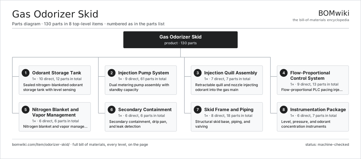
| # | Part | Qty | What it does |
|---|---|---|---|
| 1 | Odorant Storage Tank 10 parts | 1× | Sealed nitrogen-blanketed odorant storage tank with level sensing |
| 2 | Injection Pump System 9 parts | 1× | Dual metering pump assembly with standby capacity |
| 3 | Injection Quill Assembly 7 parts | 1× | Retractable quill and nozzle injecting odorant into the gas main |
| 4 | Flow-Proportional Control System 9 parts | 1× | Flow-proportional PLC pacing injection to gas flow |
| 5 | Nitrogen Blanket and Vapor Management 6 parts | 1× | Nitrogen blanket and vapor management package |
| 6 | Secondary Containment 6 parts | 1× | Secondary containment, drip pan, and leak detection |
| 7 | Skid Frame and Piping 8 parts | 1× | Structural skid base, piping, and valving |
| 8 | Instrumentation Package 6 parts | 1× | Level, pressure, and odorant concentration instruments |
3D model
No 3D model yet. Have a CAD file of this? Add a 3D model. STL renders right on this page; STEP, FreeCAD, and OpenSCAD sources are welcome too (openly licensed, like all 3D models on BOMwiki).
Build & assembly graph
expand / collapse · shared sub-assemblies converge · links to related products · est. labourTap an assembly to expand/collapse · tap a part to open it · use “Open page” for any node · drag to pan, scroll to zoom.
Bill of materials for Gas Odorizer Skid
8 top-level lines · 73 rows shown · 130 parts total · indented to 3 levels| # | Item / sub-assembly | Part no. | Qty/assy | Ext. qty | Parts | Type |
|---|---|---|---|---|---|---|
| 1 | Odorant Storage Tank 10 parts | odorizer-skid-storage-tank | 1× | 1 | 12 | assembly |
| 1.1 | Tank Shell | odorizer-skid-tank-shell | 1× | 1 | · | part |
| 1.2 | Tank Head | odorizer-skid-tank-head | 2× | 2 | · | part |
| 1.3 | Tank Manway | odorizer-skid-tank-manway | 1× | 1 | · | part |
| 1.4 | Tank Fill Port | odorizer-skid-tank-fill-port | 1× | 1 | · | part |
| 1.5 | Tank Level Transmitter | odorizer-skid-tank-level-transmitter | 1× | 1 | · | part |
| 1.6 | Magnetic Level Indicator | odorizer-skid-tank-sight-glass | 1× | 1 | · | part |
| 1.7 | Tank Vent Valve | odorizer-skid-tank-vent-valve | 1× | 1 | · | part |
| 1.8 | Tank Drain Valve | odorizer-skid-tank-drain-valve | 1× | 1 | · | part |
| 1.9 | Tank Saddle | odorizer-skid-tank-saddle | 2× | 2 | · | part |
| 1.10 | O-Ring Set | oring-set | 1× | 1 | · | part |
| 2 | Injection Pump System 9 parts | odorizer-skid-injection-pump | 1× | 1 | 61 | assembly |
| 2.1 | Metering Pump | odorizer-skid-metering-pump | 2× | 2 | · | part |
| 2.2 | Pump Diaphragm | odorizer-skid-pump-diaphragm | 2× | 2 | · | part |
| 2.3 | Pump Check Valve | odorizer-skid-pump-check-valve | 4× | 4 | · | part |
| 2.4 | Pulsation Damper | odorizer-skid-pulsation-damper | 1× | 1 | · | part |
| 2.5 | Suction Strainer | odorizer-skid-suction-strainer | 1× | 1 | · | part |
| 2.6 | Calibration Column | odorizer-skid-calibration-column | 1× | 1 | · | part |
| 2.7 | Pump Relief Valve | odorizer-skid-pump-relief-valve | 1× | 1 | · | part |
| 2.8 | Servo Motor 4 parts | servo-motor | 2× | 2 | 24 | assembly |
| 2.8.1 | Stator Assembly 3 parts + deeper › | stator-assembly | 1× | 2 | 3 | assembly |
| 2.8.2 | Rotor Assembly 4 parts + deeper › | rotor-assembly | 1× | 2 | 19 | assembly |
| 2.8.3 | Encoder | encoder | 1× | 2 | · | part |
| 2.8.4 | Motor Housing | motor-housing | 1× | 2 | · | part |
| 2.9 | O-Ring Set | oring-set | 1× | 1 | · | part |
| 3 | Injection Quill Assembly 7 parts | odorizer-skid-injection-quill | 1× | 1 | 7 | assembly |
| 3.1 | Quill Body | odorizer-skid-quill-body | 1× | 1 | · | part |
| 3.2 | Quill Nozzle | odorizer-skid-quill-nozzle | 1× | 1 | · | part |
| 3.3 | Quill Isolation Valve | odorizer-skid-quill-isolation-valve | 1× | 1 | · | part |
| 3.4 | Quill Packing Gland | odorizer-skid-quill-packing-gland | 1× | 1 | · | part |
| 3.5 | Quill Flange | odorizer-skid-quill-flange | 1× | 1 | · | part |
| 3.6 | Quill Check Valve | odorizer-skid-quill-check-valve | 1× | 1 | · | part |
| 3.7 | O-Ring Set | oring-set | 1× | 1 | · | part |
| 4 | Flow-Proportional Control System 9 parts | odorizer-skid-control-system | 1× | 1 | 13 | assembly |
| 4.1 | PLC Controller | odorizer-skid-plc | 1× | 1 | · | part |
| 4.2 | HMI Touchscreen | odorizer-skid-hmi | 1× | 1 | · | part |
| 4.3 | Flow Input Module | odorizer-skid-flow-input-module | 1× | 1 | · | part |
| 4.4 | Pump Driver | odorizer-skid-pump-driver | 1× | 1 | · | part |
| 4.5 | Control Enclosure | odorizer-skid-enclosure | 1× | 1 | · | part |
| 4.6 | Power Supply | power-supply | 1× | 1 | · | part |
| 4.7 | Relay | relay | 4× | 4 | · | part |
| 4.8 | Intrinsic Safety Barrier | odorizer-skid-barrier | 2× | 2 | · | part |
| 4.9 | Wire Bundle | wire-bundle | 1× | 1 | · | part |
| 5 | Nitrogen Blanket and Vapor Management 6 parts | odorizer-skid-nitrogen-blanket | 1× | 1 | 6 | assembly |
| 5.1 | Nitrogen Regulator | odorizer-skid-n2-regulator | 1× | 1 | · | part |
| 5.2 | Nitrogen Supply Valve | odorizer-skid-n2-supply-valve | 1× | 1 | · | part |
| 5.3 | Blanket Relief Valve | odorizer-skid-blanket-relief | 1× | 1 | · | part |
| 5.4 | Vapor Scrubber | odorizer-skid-vapor-scrubber | 1× | 1 | · | part |
| 5.5 | Flame Arrestor | odorizer-skid-flame-arrestor | 1× | 1 | · | part |
| 5.6 | Pressure Sensor | pressure-sensor | 1× | 1 | · | part |
| 6 | Secondary Containment 6 parts | odorizer-skid-containment | 1× | 1 | 6 | assembly |
| 6.1 | Drip Pan | odorizer-skid-drip-pan | 1× | 1 | · | part |
| 6.2 | Bund Wall | odorizer-skid-bund-wall | 1× | 1 | · | part |
| 6.3 | Containment Sump | odorizer-skid-sump | 1× | 1 | · | part |
| 6.4 | Leak Sensor | odorizer-skid-leak-sensor | 1× | 1 | · | part |
| 6.5 | Containment Drain Valve | odorizer-skid-containment-drain-valve | 1× | 1 | · | part |
| 6.6 | Spill Grating | odorizer-skid-spill-grating | 1× | 1 | · | part |
| 7 | Skid Frame and Piping 8 parts | odorizer-skid-skid-frame | 1× | 1 | 18 | assembly |
| 7.1 | Base Frame | odorizer-skid-base-frame | 1× | 1 | · | part |
| 7.2 | Lifting Lug | odorizer-skid-lifting-lug | 4× | 4 | · | part |
| 7.3 | Process Tubing | odorizer-skid-process-tubing | 1× | 1 | · | part |
| 7.4 | Tube Fitting | odorizer-skid-tube-fitting | 1× | 1 | · | part |
| 7.5 | Isolation Valve | odorizer-skid-isolation-valve | 4× | 4 | · | part |
| 7.6 | Pipe Support | odorizer-skid-pipe-support | 4× | 4 | · | part |
| 7.7 | Fastener Set | fastener-set | 1× | 1 | · | part |
| 7.8 | Connector | connector | 2× | 2 | · | part |
| 8 | Instrumentation Package 6 parts | odorizer-skid-instrumentation | 1× | 1 | 7 | assembly |
| 8.1 | Odorant Analyzer | odorizer-skid-odorant-analyzer | 1× | 1 | · | part |
| 8.2 | Pressure Sensor | pressure-sensor | 2× | 2 | · | part |
| 8.3 | Gas Flow Meter | odorizer-skid-flow-meter | 1× | 1 | · | part |
| 8.4 | Sample Probe | odorizer-skid-sample-probe | 1× | 1 | · | part |
| 8.5 | Junction Box | odorizer-skid-junction-box | 1× | 1 | · | part |
| 8.6 | Wire Bundle | wire-bundle | 1× | 1 | · | part |
Related products
same domain, ranked by shared parts Amine Gas Sweetening Unit
3,543 parts · shares 13 with this page
CO2 Injection Pump
463 parts · shares 13 with this page
Amine Gas Sweetening Unit
3,543 parts · shares 13 with this page
CO2 Injection Pump
463 parts · shares 13 with this page
 Condensate Stabilizer Column
2,234 parts · shares 13 with this page
Condensate Stabilizer Column
2,234 parts · shares 13 with this page
 Delayed Coker Drum
208 parts · shares 13 with this page
Delayed Coker Drum
208 parts · shares 13 with this page
 Drilling Mud Mixing System
135 parts · shares 13 with this page
Drilling Mud Mixing System
135 parts · shares 13 with this page
 Fired Process Heater
438 parts · shares 13 with this page
Fired Process Heater
438 parts · shares 13 with this page
Sourcing: possible vendors
Browse the supplier directory → Prices, MOQ, and lead times are algorithmic estimates, not quotes, and not claims about these companies. Company mappings are curated by keyword; est. price band $10k–$50M. How estimates work| Vendor | HQ | Specialty | MOQ | Lead time |
|---|---|---|---|---|
|
🇺🇸SLB
slb.com ↗
|
Houston, US | Oilfield services & equipment | made to order | 24–48 wks |
| halliburton.com ↗ | Houston, US | Oilfield services | made to order | 24–48 wks |
| bakerhughes.com ↗ | Houston, US | Energy technology | made to order | 24–48 wks |
|
🇺🇸NOV
nov.com ↗
|
Houston, US | Drilling equipment | made to order | 24–48 wks |
| technipfmc.com ↗ | London, GB | Subsea & surface systems | made to order | 24–48 wks |
1,052-word article