PCP Artificial Lift System
ProductOverview
A progressing cavity pump artificial lift system raises crude oil from a well by rotating a steel helix inside an elastomer cavity. The Downhole PCP Pump sits at the bottom of the Production Tubing String and is turned by a Sucker Rod String that runs to a Surface Drive Head at surface. The Prime Mover & Transmission drives the head, the Wellhead & Flow Tee contains pressure and routes fluid to the flow line, and the Control System sets speed and protects the equipment. The system handles heavy and sandy crude that defeats other lift methods because the pump is a low-shear, sealed-cavity device with no valves to clog.
The downhole rotor and stator pump
The pump element is a single-lobe set: a single-helix PCP Rotor (single helix) turning inside a double-helix PCP Stator. The stator has one more lobe than the rotor, so the two surfaces meet along a continuous sealing line that forms a chain of cavities. As the rotor turns, each cavity moves steadily up the pump axis, carrying a fixed volume of fluid from intake to discharge. Flow is nearly pulse-free and proportional to speed, which is why a Variable Frequency Drive can meter production directly.
The Stator Elastomer Lining is molded and bonded inside the Stator Tube, and its interference fit against the rotor sets the seal between cavities. Too much interference overheats and tears the elastomer; too little raises slip and drops volumetric efficiency. The rotor is installed to a defined depth by spacing it off the Tag Bar / Rotor Stop and Stop Bushing at the stator base, and it connects to the rod string through the Rotor Pin Coupling.
The rod string
The Sucker Rod String transmits rotation and torque from surface to the rotor. It is built from Sucker Rod joints about 25 feet long, threaded together with Rod Coupling connections. Unlike beam-pump rod strings that see axial cycling, a PCP string carries continuous torque plus the axial load of the rod weight and pump down-thrust, so rod grade and coupling makeup are selected for combined loading. Rod Centralizer units along the rod body hold the string off the tubing wall to limit rod-on-tubing wear, which is the main rod-string failure mode in deviated wells. At surface the string ends in a Polished Rod that passes through the seal, carried by a Polished Rod Clamp that lands its weight on the drive-head thrust bearing.
The surface drive head
The Surface Drive Head supports the rod string, seals the well, and turns the rod. The rod weight and hydraulic down-thrust land on the Thrust Bearing Assembly, while Ball Bearing units carry radial load on the Hollow Drive Shaft. The polished rod passes through the hollow shaft and through the Stuffing Box, whose Polished Rod Packing Set seals against the rotating rod and is adjusted at the Packing Gland to balance leakage against rod heat and wear. When the drive stops, the torque stored in the twisted rod string releases as reverse rotation; the Backspin Brake dissipates that energy through a Brake Disc and Brake Shoe set so the head and polished rod are not damaged. Shaft bores are sealed by Oil Seal elements and the cover is closed with a Fastener Set.
Prime mover and speed control
The Prime Mover & Transmission is a Electric Motor (TEFC) turning the head through either a Sheave & Belt Drive or a Gear Reducer. The belt drive uses a Motor Sheave, a Drive Head Sheave, and a Drive Belt set, and the ratio is changed by swapping sheaves. The geared option uses a Gearbox Housing and Helical Gear Pair sets for a fixed reduction. The Variable Frequency Drive varies frequency to set rotor speed, ramp starting torque, and control backspin, drawing power through its Power Supply and running its logic on an Microcontroller. The Motor Control Panel adds protection and pump-off control, reading a Pressure Sensor on tubing and casing and a Rod Torque Sensor on the rod string to detect sanding, gas interference, or stator wear.
Elastomers and materials
The Stator Elastomer Lining governs service life. NBR resists oil and abrasion at moderate temperature; HNBR extends temperature and chemical resistance for hotter or more aromatic crude. Elastomer swell from aromatics and gas, and hardening from heat, both shift the rotor interference fit, so the compound is matched to the fluid. The PCP Rotor (single helix) is chrome plated to resist the abrasion of sand-laden flow, and a worn rotor is re-chromed or replaced rather than re-machined.
Applications
The system is the standard lift for heavy oil. In cold heavy oil production with sand (CHOPS), the well deliberately produces sand with the oil, and the sealed cavities of the Downhole PCP Pump pass that slurry where valved pumps would jam. A Downhole Gas Separator below the pump lets free gas break out so the cavities stay liquid-filled, and a Tubing Torque Anchor holds the Production Tubing String against reaction torque. The same low-shear action suits high-viscosity and emulsion-prone crude, since the pump does not whip the fluid the way a high-speed centrifugal stage does.
PCP Artificial Lift System parts and their functions
7 top-level parts · 781 parts in total · full bill of materials below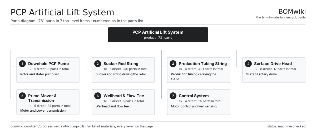
| # | Part | Qty | What it does |
|---|---|---|---|
| 1 | Downhole PCP Pump 5 parts | 1× | Rotor and stator pump set |
| 2 | Sucker Rod String 5 parts | 1× | Sucker rod string driving the rotor |
| 3 | Production Tubing String 4 parts | 1× | Production tubing carrying the stator |
| 4 | Surface Drive Head 8 parts | 1× | Surface rotary drive |
| 5 | Prime Mover & Transmission 5 parts | 1× | Motor and power transmission |
| 6 | Wellhead & Flow Tee 5 parts | 1× | Wellhead and flow tee |
| 7 | Control System 4 parts | 1× | Motor control and well sensing |
3D model
No 3D model yet. Have a CAD file of this? Add a 3D model. STL renders right on this page; STEP, FreeCAD, and OpenSCAD sources are welcome too (openly licensed, like all 3D models on BOMwiki).
Build & assembly graph
expand / collapse · shared sub-assemblies converge · links to related products · est. labourTap an assembly to expand/collapse · tap a part to open it · use “Open page” for any node · drag to pan, scroll to zoom.
Bill of materials for PCP Artificial Lift System
7 top-level lines · 67 rows shown · 781 parts total · indented to 3 levels| # | Item / sub-assembly | Part no. | Qty/assy | Ext. qty | Parts | Type |
|---|---|---|---|---|---|---|
| 1 | Downhole PCP Pump 5 parts | pcp-downhole-pump | 1× | 1 | 8 | assembly |
| 1.1 | PCP Rotor (single helix) | pcp-rotor | 1× | 1 | · | part |
| 1.2 | PCP Stator 3 parts | pcp-stator | 1× | 1 | 4 | assembly |
| 1.2.1 | Stator Tube | pcp-stator-tube | 1× | 1 | · | part |
| 1.2.2 | Stator Elastomer Lining | pcp-stator-elastomer | 1× | 1 | · | part |
| 1.2.3 | Stator End Coupling | pcp-stator-coupling | 2× | 2 | · | part |
| 1.3 | Tag Bar / Rotor Stop | pcp-tag-bar | 1× | 1 | · | part |
| 1.4 | Stop Bushing | pcp-stop-bushing | 1× | 1 | · | part |
| 1.5 | Rotor Pin Coupling | pcp-pump-pin-coupling | 1× | 1 | · | part |
| 2 | Sucker Rod String 5 parts | pcp-rod-string | 1× | 1 | 301 | assembly |
| 2.1 | Sucker Rod | pcp-sucker-rod | 120× | 120 | · | part |
| 2.2 | Rod Coupling | pcp-rod-coupling | 119× | 119 | · | part |
| 2.3 | Rod Centralizer | pcp-rod-centralizer | 60× | 60 | · | part |
| 2.4 | Polished Rod | pcp-polished-rod | 1× | 1 | · | part |
| 2.5 | Polished Rod Clamp | pcp-polished-rod-clamp | 1× | 1 | · | part |
| 3 | Production Tubing String 4 parts | pcp-tubing-string | 1× | 1 | 401 | assembly |
| 3.1 | Tubing Joint | pcp-tubing-joint | 200× | 200 | · | part |
| 3.2 | Tubing Coupling | pcp-tubing-coupling | 199× | 199 | · | part |
| 3.3 | Tubing Torque Anchor | pcp-tubing-anchor | 1× | 1 | · | part |
| 3.4 | Downhole Gas Separator | pcp-gas-separator | 1× | 1 | · | part |
| 4 | Surface Drive Head 8 parts | pcp-drive-head | 1× | 1 | 17 | assembly |
| 4.1 | Drive Head Frame | pcp-drive-frame | 1× | 1 | · | part |
| 4.2 | Hollow Drive Shaft | pcp-hollow-drive-shaft | 1× | 1 | · | part |
| 4.3 | Thrust Bearing Assembly 2 parts | pcp-thrust-bearing | 1× | 1 | 2 | assembly |
| 4.3.1 | Thrust Bearing Element | pcp-thrust-bearing-element | 1× | 1 | · | part |
| 4.3.2 | O-Ring Set | oring-set | 1× | 1 | · | part |
| 4.4 | Ball Bearing | ball-bearing | 2× | 2 | · | part |
| 4.5 | Stuffing Box 3 parts | pcp-stuffing-box | 1× | 1 | 3 | assembly |
| 4.5.1 | Polished Rod Packing Set | pcp-packing-set | 1× | 1 | · | part |
| 4.5.2 | Packing Gland | pcp-packing-gland | 1× | 1 | · | part |
| 4.5.3 | O-Ring Set | oring-set | 1× | 1 | · | part |
| 4.6 | Backspin Brake 3 parts | pcp-backspin-brake | 1× | 1 | 5 | assembly |
| 4.6.1 | Brake Disc | pcp-brake-disc | 1× | 1 | · | part |
| 4.6.2 | Brake Shoe | pcp-brake-shoe | 2× | 2 | · | part |
| 4.6.3 | Coil Spring | coil-spring | 2× | 2 | · | part |
| 4.7 | Oil Seal | oil-seal | 2× | 2 | · | part |
| 4.8 | Fastener Set | fastener-set | 1× | 1 | · | part |
| 5 | Prime Mover & Transmission 5 parts | pcp-prime-mover | 1× | 1 | 24 | assembly |
| 5.1 | Electric Motor (TEFC) | pcp-electric-motor | 1× | 1 | · | part |
| 5.2 | Sheave & Belt Drive 3 parts | pcp-belt-drive | 1× | 1 | 5 | assembly |
| 5.2.1 | Motor Sheave | pcp-motor-sheave | 1× | 1 | · | part |
| 5.2.2 | Drive Head Sheave | pcp-head-sheave | 1× | 1 | · | part |
| 5.2.3 | Drive Belt | drive-belt | 3× | 3 | · | part |
| 5.3 | Gear Reducer 4 parts | pcp-gear-reducer | 1× | 1 | 9 | assembly |
| 5.3.1 | Gearbox Housing | gearbox-housing | 1× | 1 | · | part |
| 5.3.2 | Helical Gear Pair | gear-pair | 2× | 2 | · | part |
| 5.3.3 | Ball Bearing | ball-bearing | 4× | 4 | · | part |
| 5.3.4 | Oil Seal | oil-seal | 2× | 2 | · | part |
| 5.4 | Variable Frequency Drive 3 parts | pcp-vfd | 1× | 1 | 8 | assembly |
| 5.4.1 | Power Supply | power-supply | 1× | 1 | · | part |
| 5.4.2 | Microcontroller | mcu | 1× | 1 | · | part |
| 5.4.3 | Connector | connector | 6× | 6 | · | part |
| 5.5 | Sliding Motor Base | pcp-motor-base | 1× | 1 | · | part |
| 6 | Wellhead & Flow Tee 5 parts | pcp-wellhead | 1× | 1 | 5 | assembly |
| 6.1 | Production Flow Tee | pcp-production-tee | 1× | 1 | · | part |
| 6.2 | Tubing Hanger | pcp-tubing-hanger | 1× | 1 | · | part |
| 6.3 | Pack-off / BOP | pcp-pack-off | 1× | 1 | · | part |
| 6.4 | Master Gate Valve | pcp-master-valve | 1× | 1 | · | part |
| 6.5 | Fastener Set | fastener-set | 1× | 1 | · | part |
| 7 | Control System 4 parts | pcp-control-system | 1× | 1 | 25 | assembly |
| 7.1 | Motor Control Panel 3 parts | pcp-control-panel | 1× | 1 | 14 | assembly |
| 7.1.1 | Microcontroller | mcu | 1× | 1 | · | part |
| 7.1.2 | Power Supply | power-supply | 1× | 1 | · | part |
| 7.1.3 | Connector | connector | 12× | 12 | · | part |
| 7.2 | Pressure Sensor | pressure-sensor | 2× | 2 | · | part |
| 7.3 | Rod Torque Sensor | pcp-torque-sensor | 1× | 1 | · | part |
| 7.4 | Connector | connector | 8× | 8 | · | part |
Related products
same domain, ranked by shared parts Oil Pumpjack
141 parts · shares 5 with this page
Oil Pumpjack
141 parts · shares 5 with this page
 Drilling Mud Degasser
154 parts · shares 4 with this page
Vapor Combustion Unit
287 parts · shares 4 with this page
Drilling Mud Degasser
154 parts · shares 4 with this page
Vapor Combustion Unit
287 parts · shares 4 with this page
 Wireline Logging Unit
189 parts · shares 6 with this page
Wireline Logging Unit
189 parts · shares 6 with this page
 Reciprocating Gas Compressor Package
187 parts · shares 3 with this page
CO2 Injection Pump
463 parts · shares 5 with this page
Reciprocating Gas Compressor Package
187 parts · shares 3 with this page
CO2 Injection Pump
463 parts · shares 5 with this page
Sourcing: possible vendors
Browse the supplier directory → Prices, MOQ, and lead times are algorithmic estimates, not quotes, and not claims about these companies. Company mappings are curated by keyword; est. price band $10k–$50M. How estimates work| Vendor | HQ | Specialty | MOQ | Lead time |
|---|---|---|---|---|
|
🇺🇸SLB
slb.com ↗
|
Houston, US | Oilfield services & equipment | made to order | 24–48 wks |
| halliburton.com ↗ | Houston, US | Oilfield services | made to order | 24–48 wks |
| bakerhughes.com ↗ | Houston, US | Energy technology | made to order | 24–48 wks |
|
🇺🇸NOV
nov.com ↗
|
Houston, US | Drilling equipment | made to order | 24–48 wks |
| technipfmc.com ↗ | London, GB | Subsea & surface systems | made to order | 24–48 wks |
874-word article