Oilwell Cementing Unit
ProductOverview
An oilwell Oilwell Cementing Unit is the surface equipment that places cement around the casing of an oil or gas well. After a section of casing is run into the borehole, cement slurry is pumped down inside the casing and back up the annulus between the casing and the rock. When it sets, the cement seals the annulus, supports the casing string, and isolates the producing zone from water-bearing formations above and below it. The unit performs three jobs in sequence during a single operation: it blends dry cement powder with water to a specified density, it pumps that slurry at high pressure into the well, and it records the density, pump rate, and pressure so the operator can confirm the slurry placed correctly.
The complete unit is built around two Triplex Plunger Pump assemblies driven by a single diesel Diesel Power Pack. A Recirculating Mixing System prepares the slurry, a pair of Displacement Tanks measures the volume pumped, and a high-pressure HP Discharge Manifold routes the slurry to the wellhead. The whole assembly sits on a Skid Frame that mounts to a truck chassis or a stationary skid.
High-Pressure Pumps
The core of the unit is the Triplex Plunger Pump, a positive-displacement pump with three plungers that deliver slurry against well pressures as high as 15,000 psi. Each pump is split into two halves. The Fluid End is the wetted section: a forged Fluid End Block holds three Pump Plunger bores, each served by a Suction Valve and a Discharge Valve seated on a Valve Seat and held closed by a Valve Spring. A Plunger Packing Stack seals each plunger against the block. Cement slurry is abrasive, so the plungers, valves, and seats are surface-hardened wear items replaced on a regular schedule.
The Power End converts rotation into reciprocating motion. A Crankshaft running on a Ball Bearing set drives three Connecting Rod links, each pushing a Crosshead and a Pony Rod that connects to a plunger. The crankcase is pressure-lubricated by a Crankcase Lube Pump, with an Oil Seal at each rod opening to keep oil in and slurry out.
Power and Drive
Mechanical power comes from the Diesel Engine, a turbocharged six-cylinder unit producing roughly 600 hp. It uses a cast Engine Block, six Piston Assembly sets, a forged Engine Crankshaft, and six Fuel Injector units managed by a Engine Control Unit. A Turbocharger raises charge density for the high power output. Engine output passes through a Transmission, a multi-speed gearbox that uses a Helical Gear Pair set and a Hydraulic Clutch Pack to step engine speed down to the pump shaft speed required for a given rate and pressure. A Drive Shaft couples the transmission to each triplex pump. A Engine Radiator cools the engine and a Fuel Tank feeds it through an Engine Air Filter.
Mixing the Slurry
Slurry is blended in the Recirculating Mixing System using the recirculating jet method. Water enters the Jet/Venturi Mixer, where it passes through a Venturi Throat and a Mixing Nozzle. The high-velocity jet draws dry cement from the Cement Hopper and entrains it into the stream. The throat and nozzle are lined with tungsten carbide because the cement-water mix erodes ordinary steel quickly. The mixed slurry drops into the Mixing Tub, where a Tub Agitator keeps solids in suspension. A Centrifugal Recirc Pump, a centrifugal pump built on a Stator Assembly and Rotor Assembly with a Pump Impeller in a Pump Volute, continuously recirculates slurry between the tub and the mixer. Recirculation lets the operator trim density by adding water or cement until the densitometer reads the target value before the slurry is sent downhole. A Mechanical Seal keeps slurry off the pump bearings.
Delivery and Measurement
Slurry leaves the triplex pumps through the HP Discharge Manifold, built from a forged Manifold Block, several HP Plug Valve units, and articulated Chiksan Swivel Joint joints. The swivels and Treating Iron Pup Joint sections, joined by Hammer Union connections, make up the treating iron that carries slurry to the wellhead while allowing the rig-up to flex. A Pressure Relief Valve and a Pressure Sensor protect the line against overpressure. Volume is tracked by the Displacement Tanks, a pair of calibrated Measuring Tank vessels read through a Sight Gauge. Clean displacement fluid drawn from these tanks pushes the slurry out of the casing and into the annulus at the end of the job. Water and chemicals come from the Water & Additive System, where a Water Charge Pump supplies the mixer and two Additive Metering Pump units meter liquid additives.
Instrumentation and Control
The Instrumentation & Data System system records the job. A Densitometer continuously measures slurry density, two Slurry Flow Meter units track rate, and several Pressure Sensor units watch line pressure. Their signals feed a Data Acquisition Board that logs the full job. The operator works from the Control Cabin, where the Operator Console drives engine throttle and pump rate, and two LCD Panel displays show density, rate, and pressure in real time.
Variants and Use
Units are configured as truck-mounted for land work or as skids for offshore platforms and barges. Single-pump units handle small casing jobs, while twin-pump units like this one support higher rates and provide redundancy for critical cement placements. Pressure ratings of 10,000 psi cover most shallow and intermediate casing strings, while 15,000 psi units are used on deep wells and high-pressure formations. The same unit also performs squeeze cementing to repair leaks and plug-and-abandon work to seal wells permanently at the end of their life.
Oilwell Cementing Unit parts and their functions
9 top-level parts · 902 parts in total · full bill of materials below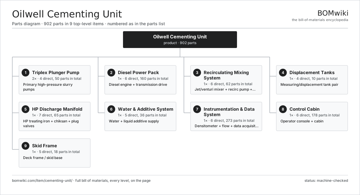
| # | Part | Qty | What it does |
|---|---|---|---|
| 1 | Triplex Plunger Pump 4 parts | 2× | Primary high-pressure slurry pumps |
| 2 | Diesel Power Pack 6 parts | 1× | Diesel engine + transmission drive |
| 3 | Recirculating Mixing System 6 parts | 1× | Jet/venturi mixer + recirc pump + tub |
| 4 | Displacement Tanks 4 parts | 1× | Measuring/displacement tank pair |
| 5 | HP Discharge Manifold 7 parts | 1× | HP treating iron + chiksan + plug valves |
| 6 | Water & Additive System 5 parts | 1× | Water + liquid additive supply |
| 7 | Instrumentation & Data System 6 parts | 1× | Densitometer + flow + data acquisition |
| 8 | Control Cabin 6 parts | 1× | Operator console + cabin |
| 9 | Skid Frame 5 parts | 1× | Deck frame / skid base |
3D model
No 3D model yet. Have a CAD file of this? Add a 3D model. STL renders right on this page; STEP, FreeCAD, and OpenSCAD sources are welcome too (openly licensed, like all 3D models on BOMwiki).
Build & assembly graph
expand / collapse · shared sub-assemblies converge · links to related products · est. labourTap an assembly to expand/collapse · tap a part to open it · use “Open page” for any node · drag to pan, scroll to zoom.
Bill of materials for Oilwell Cementing Unit
9 top-level lines · 128 rows shown · 902 parts total · indented to 3 levels| # | Item / sub-assembly | Part no. | Qty/assy | Ext. qty | Parts | Type |
|---|---|---|---|---|---|---|
| 1 | Triplex Plunger Pump 4 parts | cementing-unit-triplex-pump | 2× | 2 | 50 | assembly |
| 1.1 | Fluid End 8 parts | cementing-unit-fluid-end | 1× | 2 | 26 | assembly |
| 1.1.1 | Fluid End Block | cementing-unit-fluid-end-block | 1× | 2 | · | part |
| 1.1.2 | Pump Plunger | cementing-unit-plunger | 3× | 6 | · | part |
| 1.1.3 | Suction Valve | cementing-unit-suction-valve | 3× | 6 | · | part |
| 1.1.4 | Discharge Valve | cementing-unit-discharge-valve | 3× | 6 | · | part |
| 1.1.5 | Valve Spring | cementing-unit-valve-spring | 6× | 12 | · | part |
| 1.1.6 | Plunger Packing Stack | cementing-unit-packing-stack | 3× | 6 | · | part |
| 1.1.7 | Valve Seat | cementing-unit-valve-seat | 6× | 12 | · | part |
| 1.1.8 | O-Ring Set | oring-set | 1× | 2 | · | part |
| 1.2 | Power End 8 parts | cementing-unit-power-end | 1× | 2 | 22 | assembly |
| 1.2.1 | Power End Crankcase | cementing-unit-crankcase | 1× | 2 | · | part |
| 1.2.2 | Crankshaft | cementing-unit-crankshaft | 1× | 2 | · | part |
| 1.2.3 | Connecting Rod | cementing-unit-connecting-rod | 3× | 6 | · | part |
| 1.2.4 | Crosshead | cementing-unit-crosshead | 3× | 6 | · | part |
| 1.2.5 | Pony Rod | cementing-unit-pony-rod | 3× | 6 | · | part |
| 1.2.6 | Ball Bearing | ball-bearing | 4× | 8 | · | part |
| 1.2.7 | Oil Seal | oil-seal | 6× | 12 | · | part |
| 1.2.8 | Crankcase Lube Pump | cementing-unit-lube-pump | 1× | 2 | · | part |
| 1.3 | Pump Skid Mount | cementing-unit-pump-skid-mount | 1× | 2 | · | part |
| 1.4 | Fastener Set | fastener-set | 1× | 2 | · | part |
| 2 | Diesel Power Pack 6 parts | cementing-unit-power-pack | 1× | 1 | 160 | assembly |
| 2.1 | Diesel Engine 10 parts | cementing-unit-diesel-engine | 1× | 1 | 139 | assembly |
| 2.1.1 | Engine Block | cementing-unit-engine-block | 1× | 1 | · | part |
| 2.1.2 | Piston Assembly | cementing-unit-piston-assembly | 6× | 6 | · | part |
| 2.1.3 | Engine Crankshaft | cementing-unit-engine-crankshaft | 1× | 1 | · | part |
| 2.1.4 | Cylinder Head | cementing-unit-cylinder-head | 1× | 1 | · | part |
| 2.1.5 | Turbocharger | cementing-unit-turbocharger | 1× | 1 | · | part |
| 2.1.6 | Fuel Injector | cementing-unit-fuel-injector | 6× | 6 | · | part |
| 2.1.7 | Engine Oil Pump | cementing-unit-engine-oil-pump | 1× | 1 | · | part |
| 2.1.8 | Engine Control Unit 4 parts + deeper › | cementing-unit-ecu | 1× | 1 | 116 | assembly |
| 2.1.9 | Ball Bearing | ball-bearing | 2× | 2 | · | part |
| 2.1.10 | Oil Seal | oil-seal | 4× | 4 | · | part |
| 2.2 | Transmission 6 parts | cementing-unit-transmission | 1× | 1 | 16 | assembly |
| 2.2.1 | Transmission Case | cementing-unit-transmission-case | 1× | 1 | · | part |
| 2.2.2 | Helical Gear Pair | gear-pair | 4× | 4 | · | part |
| 2.2.3 | Hydraulic Clutch Pack | cementing-unit-clutch-pack | 1× | 1 | · | part |
| 2.2.4 | Ball Bearing | ball-bearing | 6× | 6 | · | part |
| 2.2.5 | Oil Seal | oil-seal | 3× | 3 | · | part |
| 2.2.6 | Shift Actuator | cementing-unit-shift-actuator | 1× | 1 | · | part |
| 2.3 | Drive Shaft | cementing-unit-driveshaft | 2× | 2 | · | part |
| 2.4 | Engine Radiator | cementing-unit-radiator | 1× | 1 | · | part |
| 2.5 | Fuel Tank | cementing-unit-fuel-tank | 1× | 1 | · | part |
| 2.6 | Engine Air Filter | cementing-unit-engine-air-filter | 1× | 1 | · | part |
| 3 | Recirculating Mixing System 6 parts | cementing-unit-mixing-system | 1× | 1 | 62 | assembly |
| 3.1 | Jet/Venturi Mixer 4 parts | cementing-unit-jet-mixer | 1× | 1 | 4 | assembly |
| 3.1.1 | Venturi Throat | cementing-unit-venturi-throat | 1× | 1 | · | part |
| 3.1.2 | Mixing Nozzle | cementing-unit-mixing-nozzle | 1× | 1 | · | part |
| 3.1.3 | Mixer Body | cementing-unit-mixer-body | 1× | 1 | · | part |
| 3.1.4 | O-Ring Set | oring-set | 1× | 1 | · | part |
| 3.2 | Mixing Tub | cementing-unit-mixing-tub | 1× | 1 | · | part |
| 3.3 | Centrifugal Recirc Pump 6 parts | cementing-unit-recirc-pump | 1× | 1 | 27 | assembly |
| 3.3.1 | Stator Assembly 3 parts + deeper › | stator-assembly | 1× | 1 | 3 | assembly |
| 3.3.2 | Rotor Assembly 4 parts + deeper › | rotor-assembly | 1× | 1 | 19 | assembly |
| 3.3.3 | Pump Impeller | cementing-unit-pump-impeller | 1× | 1 | · | part |
| 3.3.4 | Pump Volute | cementing-unit-pump-volute | 1× | 1 | · | part |
| 3.3.5 | Mechanical Seal | cementing-unit-mechanical-seal | 1× | 1 | · | part |
| 3.3.6 | Ball Bearing | ball-bearing | 2× | 2 | · | part |
| 3.4 | Tub Agitator 3 parts | cementing-unit-tub-agitator | 1× | 1 | 27 | assembly |
| 3.4.1 | Servo Motor 4 parts + deeper › | servo-motor | 1× | 1 | 24 | assembly |
| 3.4.2 | Agitator Paddle | cementing-unit-agitator-paddle | 1× | 1 | · | part |
| 3.4.3 | Ball Bearing | ball-bearing | 2× | 2 | · | part |
| 3.5 | Cement Hopper | cementing-unit-cement-hopper | 1× | 1 | · | part |
| 3.6 | Mix Control Valve | cementing-unit-mix-control-valve | 2× | 2 | · | part |
| 4 | Displacement Tanks 4 parts | cementing-unit-displacement-tanks | 1× | 1 | 10 | assembly |
| 4.1 | Measuring Tank | cementing-unit-measuring-tank | 2× | 2 | · | part |
| 4.2 | Sight Gauge | cementing-unit-tank-sight-gauge | 2× | 2 | · | part |
| 4.3 | Butterfly Valve | cementing-unit-tank-butterfly-valve | 4× | 4 | · | part |
| 4.4 | Tank Float Sensor | cementing-unit-tank-float-sensor | 2× | 2 | · | part |
| 5 | HP Discharge Manifold 7 parts | cementing-unit-discharge-manifold | 1× | 1 | 65 | assembly |
| 5.1 | Manifold Block | cementing-unit-manifold-block | 1× | 1 | · | part |
| 5.2 | HP Plug Valve 4 parts | cementing-unit-plug-valve | 4× | 4 | 4 | assembly |
| 5.2.1 | Valve Body | cementing-unit-valve-body | 1× | 4 | · | part |
| 5.2.2 | Valve Plug | cementing-unit-valve-plug | 1× | 4 | · | part |
| 5.2.3 | O-Ring Set | oring-set | 1× | 4 | · | part |
| 5.2.4 | Fastener Set | fastener-set | 1× | 4 | · | part |
| 5.3 | Chiksan Swivel Joint 3 parts | cementing-unit-chiksan-swivel | 6× | 6 | 4 | assembly |
| 5.3.1 | Swivel Body | cementing-unit-swivel-body | 1× | 6 | · | part |
| 5.3.2 | Ball Bearing | ball-bearing | 2× | 12 | · | part |
| 5.3.3 | O-Ring Set | oring-set | 1× | 6 | · | part |
| 5.4 | Treating Iron Pup Joint | cementing-unit-hp-pipe-pup | 8× | 8 | · | part |
| 5.5 | Hammer Union | cementing-unit-hammer-union | 12× | 12 | · | part |
| 5.6 | Pressure Relief Valve | cementing-unit-relief-valve | 2× | 2 | · | part |
| 5.7 | Pressure Sensor | pressure-sensor | 2× | 2 | · | part |
| 6 | Water & Additive System 5 parts | cementing-unit-water-additive-system | 1× | 1 | 36 | assembly |
| 6.1 | Water Tank | cementing-unit-water-tank | 1× | 1 | · | part |
| 6.2 | Water Charge Pump 5 parts | cementing-unit-charge-pump | 1× | 1 | 26 | assembly |
| 6.2.1 | Stator Assembly 3 parts + deeper › | stator-assembly | 1× | 1 | 3 | assembly |
| 6.2.2 | Rotor Assembly 4 parts + deeper › | rotor-assembly | 1× | 1 | 19 | assembly |
| 6.2.3 | Pump Impeller | cementing-unit-pump-impeller | 1× | 1 | · | part |
| 6.2.4 | Ball Bearing | ball-bearing | 2× | 2 | · | part |
| 6.2.5 | Mechanical Seal | cementing-unit-mechanical-seal | 1× | 1 | · | part |
| 6.3 | Additive Metering Pump | cementing-unit-additive-pump | 2× | 2 | · | part |
| 6.4 | Flow Control Valve | cementing-unit-flow-control-valve | 3× | 3 | · | part |
| 6.5 | Supply Hose | cementing-unit-supply-hose | 4× | 4 | · | part |
| 7 | Instrumentation & Data System 6 parts | cementing-unit-instrumentation | 1× | 1 | 273 | assembly |
| 7.1 | Densitometer 4 parts | cementing-unit-densitometer | 1× | 1 | 63 | assembly |
| 7.1.1 | Density Sensing Cell | cementing-unit-density-cell | 1× | 1 | · | part |
| 7.1.2 | Bare PCB | pcb-bare | 1× | 1 | · | part |
| 7.1.3 | Microcontroller | mcu | 1× | 1 | · | part |
| 7.1.4 | SMD Passive (R/C/L) | smd-passives | 60× | 60 | · | part |
| 7.2 | Slurry Flow Meter | cementing-unit-flow-meter | 2× | 2 | · | part |
| 7.3 | Pressure Sensor | pressure-sensor | 4× | 4 | · | part |
| 7.4 | Data Acquisition Board 4 parts | cementing-unit-data-acq-board | 1× | 1 | 191 | assembly |
| 7.4.1 | Bare PCB | pcb-bare | 1× | 1 | · | part |
| 7.4.2 | Microcontroller | mcu | 2× | 2 | · | part |
| 7.4.3 | Connector | connector | 8× | 8 | · | part |
| 7.4.4 | SMD Passive (R/C/L) | smd-passives | 180× | 180 | · | part |
| 7.5 | Wire Bundle | wire-bundle | 1× | 1 | · | part |
| 7.6 | Connector | connector | 12× | 12 | · | part |
| 8 | Control Cabin 6 parts | cementing-unit-control-cabin | 1× | 1 | 178 | assembly |
| 8.1 | Cabin Shell | cementing-unit-cabin-shell | 1× | 1 | · | part |
| 8.2 | Operator Console 5 parts | cementing-unit-operator-console | 1× | 1 | 166 | assembly |
| 8.2.1 | Bare PCB | pcb-bare | 1× | 1 | · | part |
| 8.2.2 | Microcontroller | mcu | 1× | 1 | · | part |
| 8.2.3 | Control Switch | cementing-unit-control-switch | 8× | 8 | · | part |
| 8.2.4 | Connector | connector | 16× | 16 | · | part |
| 8.2.5 | SMD Passive (R/C/L) | smd-passives | 140× | 140 | · | part |
| 8.3 | LCD Panel | lcd-panel | 2× | 2 | · | part |
| 8.4 | Throttle Control | cementing-unit-throttle-control | 2× | 2 | · | part |
| 8.5 | Power Supply | power-supply | 1× | 1 | · | part |
| 8.6 | Sheet Metal Panel | sheet-panel | 6× | 6 | · | part |
| 9 | Skid Frame 5 parts | cementing-unit-skid-frame | 1× | 1 | 18 | assembly |
| 9.1 | Main Beam | cementing-unit-main-beam | 4× | 4 | · | part |
| 9.2 | Cross Member | cementing-unit-cross-member | 8× | 8 | · | part |
| 9.3 | Deck Plate | cementing-unit-deck-plate | 1× | 1 | · | part |
| 9.4 | Lifting Lug | cementing-unit-lifting-lug | 4× | 4 | · | part |
| 9.5 | Fastener Set | fastener-set | 1× | 1 | · | part |
Related products
same domain, ranked by shared parts Wireline Logging Unit
189 parts · shares 18 with this page
Wireline Logging Unit
189 parts · shares 18 with this page
 Drilling Mud Mixing System
135 parts · shares 16 with this page
Drilling Mud Mixing System
135 parts · shares 16 with this page
 Shale Shaker
201 parts · shares 15 with this page
Shale Shaker
201 parts · shares 15 with this page
 Amine Gas Sweetening Unit
3,543 parts · shares 15 with this page
Amine Gas Sweetening Unit
3,543 parts · shares 15 with this page
 Condensate Stabilizer Column
2,234 parts · shares 15 with this page
Condensate Stabilizer Column
2,234 parts · shares 15 with this page
Sourcing: possible vendors
Browse the supplier directory → Prices, MOQ, and lead times are algorithmic estimates, not quotes, and not claims about these companies. Company mappings are curated by keyword; est. price band $10k–$50M. How estimates work| Vendor | HQ | Specialty | MOQ | Lead time |
|---|---|---|---|---|
|
🇺🇸SLB
slb.com ↗
|
Houston, US | Oilfield services & equipment | made to order | 24–48 wks |
| halliburton.com ↗ | Houston, US | Oilfield services | made to order | 24–48 wks |
| bakerhughes.com ↗ | Houston, US | Energy technology | made to order | 24–48 wks |
|
🇺🇸NOV
nov.com ↗
|
Houston, US | Drilling equipment | made to order | 24–48 wks |
| technipfmc.com ↗ | London, GB | Subsea & surface systems | made to order | 24–48 wks |
1,042-word article