JT Gas Dew Point Skid
ProductOverview
A Joule-Thomson skid conditions natural gas by chilling it through a pressure drop, condensing out the heavy hydrocarbons and water that would otherwise drop out later in a pipeline or limit the gas's salability. The skid exploits the Joule-Thomson effect: when a real gas expands across a restriction without doing external work, it cools. A wellstream often arrives at much higher pressure than the sales line needs, and that surplus pressure is the refrigeration source. Letting it down across a JT Choke Valve drops the temperature enough to knock out condensable liquids, lowering both the hydrocarbon dew point and the water dew point of the gas that goes to sale. A skid handles 1 to 100 MMSCFD and is most economical where high inlet pressure is available for free.
The skid is a small refrigeration plant with no compressor. Inlet gas is pre-cooled against cold product gas, expanded through the JT valve to chill it further, and the condensed liquid is dropped out in a cold separator. The cold sales gas is then warmed back up by pre-cooling the next increment of inlet gas. The only added energy is the heat that reconcentrates the hydrate inhibitor.
Inlet conditioning and pre-cooling
Wet, warm gas first enters the Inlet Separator, which removes free liquid and any slug of water or condensate before the cold section. An Inlet Cyclone spins out the bulk liquid and a Demister Pad catches the fine mist, because liquid carried into the cold exchanger would foul it and upset the dew point control.
The dry gas then enters the tube side of the Gas-Gas Exchanger, where it is pre-cooled against the cold gas leaving the low-temperature separator. This cross exchange is what makes the skid efficient: the refrigeration produced at the JT valve is recovered to chill incoming gas, so the valve only has to supply the incremental cooling. A larger exchanger recovers more cold and deepens the achievable dew point depression for a given pressure drop.
Expansion and cold separation
The pre-cooled gas reaches the Joule-Thomson Valve Station. The JT Choke Valve throttles the gas from inlet to sales pressure, and the expansion drops the temperature by roughly 5 to 8 degrees F for every 100 psi of pressure let down. The valve uses an anti-erosion Anti-Erosion Cage and stainless trim because the high-velocity, two-phase flow across the choke is erosive. A Bypass Valve and a fixed Fixed Choke give turndown and a startup path.
The chilled two-phase stream flows into the Low-Temperature Separator, a low-temperature three-phase vessel. The condensed hydrocarbon liquid and the aqueous inhibitor settle out while cold dry gas leaves the top and returns through the gas-gas exchanger. The cold separator vessel and the chilled piping use impact-tested low-temperature steel, since ordinary carbon steel becomes brittle at the cold separator's operating temperature, which can fall well below zero.
Hydrate inhibition
Chilling a wet gas stream invites hydrate formation. Natural gas hydrates are ice-like solids of water and light hydrocarbons that form at temperatures well above the freezing point when pressure is high, and they plug valves, exchangers and lines. The Hydrate Inhibition system prevents them by dosing methanol or monoethylene glycol upstream of the cold section through an Injection Quill. The Inhibitor Injection Pump meters the inhibitor at a rate matched to the water rate and the cold temperature. The inhibitor depresses the hydrate formation temperature so the cold separator can run below the uninhibited hydrate point without plugging.
Liquid handling and heat
The Liquid Handling section deals with the recovered liquid. The hydrocarbon condensate is pumped by the Condensate Pump to storage or to a stabilizer, metered through a Liquid Flow Meter. The aqueous phase is the rich, water-diluted inhibitor, which the Water Coalescer separates from any entrained hydrocarbon so it can be regenerated and reused.
The Heat Medium System system supplies the only significant heat input. A Fired Heater, an indirect bath or hot oil unit, warms a heat medium loop that reconcentrates the recovered inhibitor by boiling off its absorbed water and keeps the warm gas path above hydrate temperature during startup. Because it is fired equipment, the heater carries an Burner Management System burner management system to NFPA 86 that proves flame and trips fuel on a fault.
Control, insulation and materials
The Control System sets the JT valve to hold the target dew point: a deeper pressure drop gives a colder separator and a lower dew point, traded against the sales pressure that must be delivered. It also manages the separator levels, the inhibitor dosing rate and the heater. A Dew Point Analyzer confirms the hydrocarbon and water dew points of the sales gas.
The cold lines on the Skid Base and Piping carry closed-cell Cold-Service Insulation to limit heat gain and prevent external icing, and the chilled piping uses ASTM A333 low-temperature steel. The warm process vessels are carbon steel to ASME Section VIII, the cold separator and chilled spools are impact-tested grades, and process piping follows ASME B31.3. The skid is sized using GPSA dew point control practice, balancing available inlet pressure against the dew point depression the contract requires.
JT Gas Dew Point Skid parts and their functions
9 top-level parts · 441 parts in total · full bill of materials below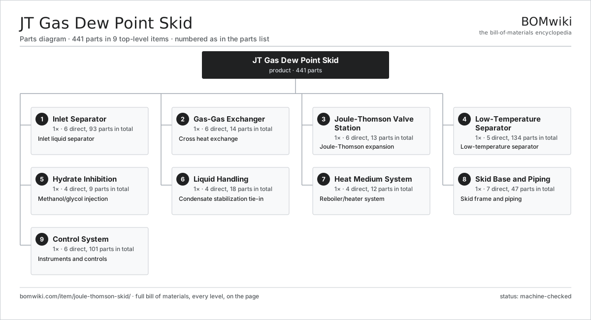
| # | Part | Qty | What it does |
|---|---|---|---|
| 1 | Inlet Separator 6 parts | 1× | Inlet liquid separator |
| 2 | Gas-Gas Exchanger 6 parts | 1× | Cross heat exchange |
| 3 | Joule-Thomson Valve Station 6 parts | 1× | Joule-Thomson expansion |
| 4 | Low-Temperature Separator 5 parts | 1× | Low-temperature separator |
| 5 | Hydrate Inhibition 4 parts | 1× | Methanol/glycol injection |
| 6 | Liquid Handling 4 parts | 1× | Condensate stabilization tie-in |
| 7 | Heat Medium System 4 parts | 1× | Reboiler/heater system |
| 8 | Skid Base and Piping 7 parts | 1× | Skid frame and piping |
| 9 | Control System 6 parts | 1× | Instruments and controls |
3D model
No 3D model yet. Have a CAD file of this? Add a 3D model. STL renders right on this page; STEP, FreeCAD, and OpenSCAD sources are welcome too (openly licensed, like all 3D models on BOMwiki).
Build & assembly graph
expand / collapse · shared sub-assemblies converge · links to related products · est. labourTap an assembly to expand/collapse · tap a part to open it · use “Open page” for any node · drag to pan, scroll to zoom.
Bill of materials for JT Gas Dew Point Skid
9 top-level lines · 102 rows shown · 441 parts total · indented to 3 levels| # | Item / sub-assembly | Part no. | Qty/assy | Ext. qty | Parts | Type |
|---|---|---|---|---|---|---|
| 1 | Inlet Separator 6 parts | jts-inlet-separator | 1× | 1 | 93 | assembly |
| 1.1 | Separator Vessel | jts-separator-vessel | 1× | 1 | · | part |
| 1.2 | Demister Pad | jts-demister-pad | 1× | 1 | · | part |
| 1.3 | Inlet Cyclone | jts-inlet-cyclone | 1× | 1 | · | part |
| 1.4 | Level Control Loop 2 parts | jts-level-control | 2× | 2 | 44 | assembly |
| 1.4.1 | Level Transmitter 4 parts + deeper › | jts-level-transmitter | 1× | 2 | 43 | assembly |
| 1.4.2 | Level Control Valve | jts-level-valve | 1× | 2 | · | part |
| 1.5 | Liquid Dump Valve | jts-dump-valve | 1× | 1 | · | part |
| 1.6 | Pressure Sensor | pressure-sensor | 1× | 1 | · | part |
| 2 | Gas-Gas Exchanger 6 parts | jts-gas-gas-exchanger | 1× | 1 | 14 | assembly |
| 2.1 | Exchanger Shell | jts-exchanger-shell | 1× | 1 | · | part |
| 2.2 | Tube Bundle | jts-tube-bundle | 1× | 1 | · | part |
| 2.3 | Tubesheet | jts-tubesheet | 2× | 2 | · | part |
| 2.4 | Baffle Plate | jts-baffle | 8× | 8 | · | part |
| 2.5 | O-Ring Set | oring-set | 1× | 1 | · | part |
| 2.6 | Fastener Set | fastener-set | 1× | 1 | · | part |
| 3 | Joule-Thomson Valve Station 6 parts | jts-jt-valve-station | 1× | 1 | 13 | assembly |
| 3.1 | JT Choke Valve 4 parts | jts-jt-valve | 1× | 1 | 4 | assembly |
| 3.1.1 | Valve Body | jts-valve-body | 1× | 1 | · | part |
| 3.1.2 | Valve Trim | jts-valve-trim | 1× | 1 | · | part |
| 3.1.3 | Anti-Erosion Cage | jts-valve-cage | 1× | 1 | · | part |
| 3.1.4 | O-Ring Set | oring-set | 1× | 1 | · | part |
| 3.2 | Bypass Valve | jts-bypass-valve | 1× | 1 | · | part |
| 3.3 | Fixed Choke | jts-choke | 1× | 1 | · | part |
| 3.4 | Valve Actuator 3 parts | jts-valve-actuator | 1× | 1 | 3 | assembly |
| 3.4.1 | Actuator Diaphragm | jts-actuator-diaphragm | 1× | 1 | · | part |
| 3.4.2 | Coil Spring | coil-spring | 1× | 1 | · | part |
| 3.4.3 | Valve Positioner | jts-positioner | 1× | 1 | · | part |
| 3.5 | Pressure Sensor | pressure-sensor | 2× | 2 | · | part |
| 3.6 | RTD Temperature Probe | temperature-rtd | 2× | 2 | · | part |
| 4 | Low-Temperature Separator 5 parts | jts-cold-separator | 1× | 1 | 134 | assembly |
| 4.1 | Cold Separator Vessel | jts-cold-vessel | 1× | 1 | · | part |
| 4.2 | Demister Pad | jts-demister-pad | 1× | 1 | · | part |
| 4.3 | Internal Warming Coil | jts-cold-coil | 1× | 1 | · | part |
| 4.4 | Level Control Loop 2 parts | jts-level-control | 2× | 2 | 44 | assembly |
| 4.4.1 | Level Transmitter 4 parts + deeper › | jts-level-transmitter | 1× | 2 | 43 | assembly |
| 4.4.2 | Level Control Valve | jts-level-valve | 1× | 2 | · | part |
| 4.5 | Interface Level Controller 4 parts | jts-interface-controller | 1× | 1 | 43 | assembly |
| 4.5.1 | Bare PCB | pcb-bare | 1× | 1 | · | part |
| 4.5.2 | Microcontroller | mcu | 1× | 1 | · | part |
| 4.5.3 | Analog Front-End IC | afe-ic | 1× | 1 | · | part |
| 4.5.4 | SMD Passive (R/C/L) | smd-passives | 40× | 40 | · | part |
| 5 | Hydrate Inhibition 4 parts | jts-hydrate-inhibition | 1× | 1 | 9 | assembly |
| 5.1 | Inhibitor Injection Pump 5 parts | jts-inhibitor-pump | 1× | 1 | 5 | assembly |
| 5.1.1 | Metering Pump Head | jts-pump-head | 1× | 1 | · | part |
| 5.1.2 | Pump Motor | jts-pump-motor | 1× | 1 | · | part |
| 5.1.3 | Metering Plunger | jts-pump-plunger | 1× | 1 | · | part |
| 5.1.4 | Coil Spring | coil-spring | 1× | 1 | · | part |
| 5.1.5 | O-Ring Set | oring-set | 1× | 1 | · | part |
| 5.2 | Inhibitor Tank | jts-inhibitor-tank | 1× | 1 | · | part |
| 5.3 | Injection Quill | jts-injection-nozzle | 2× | 2 | · | part |
| 5.4 | Inhibitor Filter | jts-inhibitor-filter | 1× | 1 | · | part |
| 6 | Liquid Handling 4 parts | jts-liquid-handling | 1× | 1 | 18 | assembly |
| 6.1 | Condensate Pump 4 parts | jts-condensate-pump | 1× | 1 | 10 | assembly |
| 6.1.1 | Pump Hydraulic End | jts-cond-pump-head | 1× | 1 | · | part |
| 6.1.2 | Pump Motor | jts-pump-motor | 1× | 1 | · | part |
| 6.1.3 | Mechanical Seal Cartridge 3 parts + deeper › | mechanical-seal-cartridge | 1× | 1 | 6 | assembly |
| 6.1.4 | Ball Bearing | ball-bearing | 2× | 2 | · | part |
| 6.2 | Condensate Cooler | jts-condensate-cooler | 1× | 1 | · | part |
| 6.3 | Water Coalescer 2 parts | jts-water-coalescer | 1× | 1 | 5 | assembly |
| 6.3.1 | Coalescer Vessel | jts-coalescer-vessel | 1× | 1 | · | part |
| 6.3.2 | Coalescer Element | jts-coalescer-element | 4× | 4 | · | part |
| 6.4 | Liquid Flow Meter | jts-flow-meter | 2× | 2 | · | part |
| 7 | Heat Medium System 4 parts | jts-heat-medium | 1× | 1 | 12 | assembly |
| 7.1 | Fired Heater 4 parts | jts-fired-heater | 1× | 1 | 6 | assembly |
| 7.1.1 | Heater Vessel | jts-heater-vessel | 1× | 1 | · | part |
| 7.1.2 | Gas Burner 3 parts + deeper › | jts-burner | 1× | 1 | 3 | assembly |
| 7.1.3 | Firetube | jts-firetube | 1× | 1 | · | part |
| 7.1.4 | RTD Temperature Probe | temperature-rtd | 1× | 1 | · | part |
| 7.2 | Process Heat Coil | jts-heat-coil | 1× | 1 | · | part |
| 7.3 | Heat Medium Pump 3 parts | jts-circulation-pump | 1× | 1 | 4 | assembly |
| 7.3.1 | Pump Hydraulic End | jts-cond-pump-head | 1× | 1 | · | part |
| 7.3.2 | Pump Motor | jts-pump-motor | 1× | 1 | · | part |
| 7.3.3 | Ball Bearing | ball-bearing | 2× | 2 | · | part |
| 7.4 | Expansion Tank | jts-expansion-tank | 1× | 1 | · | part |
| 8 | Skid Base and Piping 7 parts | jts-skid-base | 1× | 1 | 47 | assembly |
| 8.1 | Structural Skid Frame | jts-skid-frame | 1× | 1 | · | part |
| 8.2 | Process Pipe Spool | jts-pipe-spool | 1× | 1 | · | part |
| 8.3 | Pipe Flange | jts-pipe-flange | 28× | 28 | · | part |
| 8.4 | Block Valve | jts-block-valve | 12× | 12 | · | part |
| 8.5 | Relief Valve | jts-relief-valve | 3× | 3 | · | part |
| 8.6 | Cold-Service Insulation | jts-insulation | 1× | 1 | · | part |
| 8.7 | Fastener Set | fastener-set | 1× | 1 | · | part |
| 9 | Control System 6 parts | jts-control-system | 1× | 1 | 101 | assembly |
| 9.1 | Control Panel 4 parts | jts-control-panel | 1× | 1 | 35 | assembly |
| 9.1.1 | Sheet Metal Panel | sheet-panel | 1× | 1 | · | part |
| 9.1.2 | Relay | relay | 6× | 6 | · | part |
| 9.1.3 | Terminal Block | jts-terminal-block | 24× | 24 | · | part |
| 9.1.4 | Circuit Breaker | jts-circuit-breaker | 4× | 4 | · | part |
| 9.2 | Dew Point Analyzer 4 parts | jts-dew-point-analyzer | 1× | 1 | 53 | assembly |
| 9.2.1 | Bare PCB | pcb-bare | 1× | 1 | · | part |
| 9.2.2 | Microcontroller | mcu | 1× | 1 | · | part |
| 9.2.3 | Analog Front-End IC | afe-ic | 1× | 1 | · | part |
| 9.2.4 | SMD Passive (R/C/L) | smd-passives | 50× | 50 | · | part |
| 9.3 | Burner Management System 4 parts | jts-bms | 1× | 1 | 7 | assembly |
| 9.3.1 | Bare PCB | pcb-bare | 1× | 1 | · | part |
| 9.3.2 | Microcontroller | mcu | 1× | 1 | · | part |
| 9.3.3 | Flame Scanner | jts-flame-scanner | 1× | 1 | · | part |
| 9.3.4 | Relay | relay | 4× | 4 | · | part |
| 9.4 | Pressure Sensor | pressure-sensor | 4× | 4 | · | part |
| 9.5 | Power Supply | power-supply | 1× | 1 | · | part |
| 9.6 | Wire Bundle | wire-bundle | 1× | 1 | · | part |
Related products
same domain, ranked by shared parts Amine Gas Sweetening Unit
3,543 parts · shares 9 with this page
LACT Custody Transfer Unit
554 parts · shares 9 with this page
TEG Gas Dehydration Skid
587 parts · shares 8 with this page
Amine Gas Sweetening Unit
3,543 parts · shares 9 with this page
LACT Custody Transfer Unit
554 parts · shares 9 with this page
TEG Gas Dehydration Skid
587 parts · shares 8 with this page
 Condensate Stabilizer Column
2,234 parts · shares 8 with this page
Condensate Stabilizer Column
2,234 parts · shares 8 with this page
 Gas Metering Skid
1,491 parts · shares 5 with this page
Gas Metering Skid
1,491 parts · shares 5 with this page
 Wireline Logging Unit
189 parts · shares 5 with this page
Wireline Logging Unit
189 parts · shares 5 with this page
Sourcing: possible vendors
Browse the supplier directory → Prices, MOQ, and lead times are algorithmic estimates, not quotes, and not claims about these companies. Company mappings are curated by keyword; est. price band $10k–$50M. How estimates work| Vendor | HQ | Specialty | MOQ | Lead time |
|---|---|---|---|---|
|
🇺🇸SLB
slb.com ↗
|
Houston, US | Oilfield services & equipment | made to order | 24–48 wks |
| halliburton.com ↗ | Houston, US | Oilfield services | made to order | 24–48 wks |
| bakerhughes.com ↗ | Houston, US | Energy technology | made to order | 24–48 wks |
|
🇺🇸NOV
nov.com ↗
|
Houston, US | Drilling equipment | made to order | 24–48 wks |
| technipfmc.com ↗ | London, GB | Subsea & surface systems | made to order | 24–48 wks |
894-word article